Econ ELA100 Installation & Operation Manual
Electric actuator
Hide thumbs
Also See for ELA100:
- Installation & operation manual (57 pages) ,
- Installation & operation manual (67 pages)
Table of Contents
Advertisement
Installation & Operation Manual
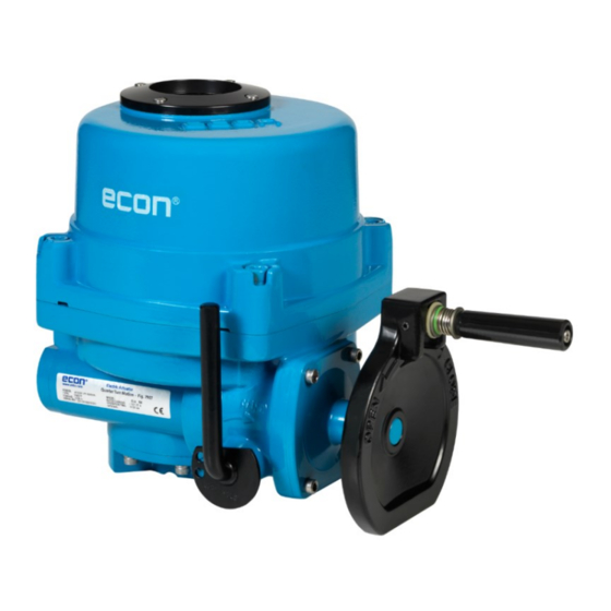
Fig. 7907, type ELA80 - 3000
Scan for manual
ELA80, 100, 150, 200, 300, 500, 600, 800, 1200, 2000, 2700 & 3000
ECON actuator Fig 7907, type ELA80 – 3000
Rev.23 – August, 2023
ECON ELECTRIC ACTUATOR
Installation and Operation Manual for actuator type:
Proven Quality since 1892
Compact quarter turn actuator
Mechanical position indicator
High output torque
Multi mounting base
Manual override
o, Republic :
www.eriks.com
Advertisement
Table of Contents

Related Manuals for Econ ELA100


Summary of Contents for Econ ELA100
- Page 1 Manual override Scan for manual Installation and Operation Manual for actuator type: ELA80, 100, 150, 200, 300, 500, 600, 800, 1200, 2000, 2700 & 3000 o, Republic : ECON actuator Fig 7907, type ELA80 – 3000 www.eriks.com Rev.23 – August, 2023...
-
Page 2: Table Of Contents
4.9.2 PCU-D Proportional Control Unit Direct Current 4.9.3 LED Signal Indication 4.9.4 Setting PCU Functions 4.9.5 PCU-EB Proportional Control Unit Alternating Current (2020 version) 4.10 AC/DC Multi-Board (Optional) ECON actuator Fig. 7907, type ELA80 – 3000 www.eriks.com Rev.23 – August, 2023... - Page 3 ModBus Controler 6.2.1 Specification 7. OPERATION Electrical Connections and Preliminary Test 8. MAINTENANCE Maintenance Tools 9. TROUBLE SHOOTING 10. INSTALLATION AND MAINTENANCE TIPS 11. WIRING DIAGRAMS 12. GROUNDING ECON actuator Fig. 7907, type ELA80 – 3000 www.eriks.com Rev.23 – August, 2023...
-
Page 4: Introduction
Note: Information in this manual is critical to the user’s understanding of the actuator’s installation and operation ECON actuator Fig. 7907, type ELA80 – 3000 www.eriks.com Rev.23 – August, 2023... -
Page 5: Product Identification
*The production date is incorporated in the serial number: For example: SER.#: EW21 01- 0001, in which 21 represents the production year 2021 and 01 represents the production month January. ECON actuator Fig. 7907, type ELA80 – 3000 www.eriks.com Rev.23 – August, 2023... -
Page 6: Applied Standards
Actuators must be stored in a clean, cool and dry area. The unit should be stored with the cover installed and the conduit openings sealed. Storage must be off the floor, covered with a sealed dust protector. ECON actuator Fig. 7907, type ELA80 – 3000 www.eriks.com Rev.23 – August, 2023... -
Page 7: General Information And Features
2. 24VAC actuators have 24VDC motors. 3. 115VAC and 230VAC ±5% according to IEC 60034-1 4. Duty ratings: ELA80 and ELA100 in 380 VAC/3Ph – S4-70% and 440 VAC/3Ph - S4-40%. ECON actuator Fig. 7907, type ELA80 – 3000 www.eriks.com... -
Page 8: Ela-Series Options
Turn the hand-wheel until the valve reaches the required position. • Turn clockwise to close and counter-clockwise to open. Note: The manual override lever returns automatically to auto-position when the actuator is operated electrically. ECON actuator Fig. 7907, type ELA80 – 3000 www.eriks.com Rev.23 – August, 2023... -
Page 9: Lubrication
3.2.2 ELA2000 - 3000 (Actuator + Gear Box) Top cover Window & Indicator Handwheel Body Lever Actuator base Mechanical travel stops Gear box including Driving bushing ECON actuator Fig. 7907, type ELA80 – 3000 www.eriks.com Rev.23 – August, 2023... -
Page 10: Internal Parts For Standard Models
Internal Parts for Standard Models 3.3.1 ELA80 - 3000 Motor Limit switch Terminal assembly block Capacitor Torque switch assembly Note: ELA80 and ELA100 do not have a torque switch provision! ECON actuator Fig. 7907, type ELA80 – 3000 www.eriks.com Rev.23 – August, 2023... -
Page 11: Installation
CAUTION: Do not attempt to work on your ECON actuator without first shutting off the power supply Do not attach ropes or hooks to the hand wheel for lifting purposes ECON actuator Fig. -
Page 12: Actuator Mounting Base Details (Iso 5211)
DS 22mm • ELA1200 DS 27mm DS 22-30mm • ELA2000 DS 36mm DS 27-46-55mm • ELA2000 DS 36mm DS 27-46-55mm • ELA3000 DS 46mm DS 27-36-55mm Pitch ECON actuator Fig. 7907, type ELA80 – 3000 www.eriks.com Rev.23 – August, 2023... -
Page 13: Limit Switch Setting
Rotate the OPEN cam CCW until the limit switch ‘clicks’ (see Figure 2) Tighten the set screw with the Allen key. • DANGER: HAZARDOUS VOLTAGE. Make sure all incoming power is disconnected before setting the limit switches ECON actuator Fig. 7907, type ELA80 – 3000 www.eriks.com Rev.23 – August, 2023... -
Page 14: Torque Switch Setting
The torque switches are set by manufacturer on the production site. If re-setting is necessary, please contact the ECON actuator distributer before setting the torque switch. CAUTION: Do not reset the torque switch to a setting higher than the maximum setting stated by the manufacturer. -
Page 15: Setting Potentiometer (Optional)
1 s at (Rated VAC x 2 + 1000) x 1.2 (from Input to power ground) Insulation Resistance Above 500V DC 30MΩ Vibration 10g, 0~34Hz 14 | P a g e ECON actuator Fig. 7907, type ELA80 – 3000 www.eriks.com Rev.23 – August, 2023... -
Page 16: Calibration Of Zero And Span - Cpt
When the actuator is in the fully open position, adjust the SPAN open setting on the CPT board until an output value of 20mA is achieved. Zero dial Span dial ECON actuator Fig. 7907, type ELA80 – 3000 www.eriks.com Rev.23 – August, 2023... -
Page 17: Proportional Control Units - Pcu (Optional)
However, we strongly recommend that input power, signal input selection and DIP switches are to be verified prior to the actuator start up. Settings the PCU functions are shown in paragraph 4.9.3 and 4.9.4. ECON actuator Fig. 7907, type ELA80 – 3000 www.eriks.com Rev.23 – August, 2023... -
Page 18: Pcu-D Proportional Control Unit Direct Current
However, we strongly recommend that input power, signal input selection and DIP switches are to be verified prior to the actuator start up. Settings the PCU functions are shown in paragraph 4.9.3 and 4.9.4. ECON actuator Fig. 7907, type ELA80 – 3000 www.eriks.com Rev.23 – August, 2023... -
Page 19: Led Signal Indication
60 Hz (not applicable for PCU-D) 50 Hz (not applicable for PCU-D) Note: If not specified, the factory setting of the input signal is 4 - 20mA. ECON actuator Fig. 7907, type ELA80 – 3000 www.eriks.com Rev.23 – August, 2023... - Page 20 17 and 18, while opening and closing the actuator. If necessary adjust the potentiometers “zero” and “span” on the bottom of the circuit board until the output values are correct. ECON actuator Fig. 7907, type ELA80 – 3000 www.eriks.com Rev.23 – August, 2023...
- Page 21 Signal: 4.3~4mA Fully Closed Auto-Full Switch (Switch 3) On (up) Signal: 19.7~20mA Fully Open Signal: 4mA Fully Closed Auto-Full Switch (Switch 3) Off (down) Signal: 20mA Fully Open ECON actuator Fig. 7907, type ELA80 – 3000 www.eriks.com Rev.23 – August, 2023...
- Page 22 2 seconds. In both cases, the yellow LED will be lit off to indicate the termination of the Manual Operation Mode. Note: During the Manual Operation mode, the input signal is ignored. ECON actuator Fig. 7907, type ELA80 – 3000 www.eriks.com Rev.23 – August, 2023...
- Page 23 • Turning the Delay Time Dial in clockwise direction will increase the deadtime time (Range 0.05 to 7.5 seconds). Dial 0.05 Sec. Dial Sec. ECON actuator Fig. 7907, type ELA80 – 3000 www.eriks.com Rev.23 – August, 2023...
-
Page 24: Pcu-Eb Proportional Control Unit Alternating Current (2020 Version)
Please be noted that two PCU Alternating Current PCB’s are available. Check the markings on the PCB before you start working on the settings. The instructions below are only applicable to the PCU-EB PCB. PCU-EB-V1.5 ECON actuator Fig. 7907, type ELA80 – 3000 www.eriks.com Rev.23 – August, 2023... - Page 25 X, Y & Z, 10g (6g based on RMF), Frequency: 0.2~34Hz, Time: 30 minutes A) LED Signal Indication Signal Open Blue Power or Auto Green Close Yellow Manual or Fault ECON actuator Fig. 7907, type ELA80 – 3000 www.eriks.com Rev.23 – August, 2023...
- Page 26 By Dip Switch Note: 4-20mA is the standard factory setting for the output signal of this PCU. CAUTION: “(1) Selection of input signal” ZERO SWITCH (SW7.3) Usage Notes ECON actuator Fig. 7907, type ELA80 – 3000 www.eriks.com Rev.23 – August, 2023...
- Page 27 : 0.25s increase per step (0.25 ~ 1 sec) ③ Step 5 ~ 15 : 0.50s increase per step (2.5 ~ 7.5 sec) ④ Factory setting : “2” ECON actuator Fig. 7907, type ELA80 – 3000 www.eriks.com Rev.23 – August, 2023...
- Page 28 Note: The Auto Setting command is cancelled automatically when any button (Zero, Span or A-scan) is pressed during the Auto Setting mode. ECON actuator Fig. 7907, type ELA80 – 3000 www.eriks.com Rev.23 – August, 2023...
- Page 29 Please set full close (zero) to 5mA DC and set fully open (span) to 19mA DC Put dip switch No. 4 ON (SW3). ① RED & GREEN LED start blinking together. ② ECON actuator Fig. 7907, type ELA80 – 3000 www.eriks.com Rev.23 – August, 2023...
- Page 30 OFF position during the setting procedure. - If, during the above procedure, there is any input signal for longer than 2 minutes the setting procedure is being cancelled. ECON actuator Fig. 7907, type ELA80 – 3000 www.eriks.com Rev.23 – August, 2023...
- Page 31 Input signal initialization error Auto Setting initialization error Input signal error Motor backlashing Command signal select switch error POTENTIOMETER Open position error Close position error Limit switch error ECON actuator Fig. 7907, type ELA80 – 3000 www.eriks.com Rev.23 – August, 2023...
-
Page 32: Ac/Dc Multi-Board (Optional)
Note: Don’t operate both switches #1 and #2 at the same time. It may damage the board C) Motor Terminal Block Red motor wire must be connected to terminal # 1 • Black motor wire must be connected to terminal # 2 • ECON actuator Fig. 7907, type ELA80 – 3000 www.eriks.com Rev.23 – August, 2023... -
Page 33: Rechargeable Battery Pack - Rbp (Optional)
The battery must be discharged and charged regularly every 2 to 3 months. General The ECON actuator with Rechargeable Battery Pack (RBP) can be operated in Local or Remote mode by using two selector switches on the local control unit. During power failure the actuator can be operated 5 times by the battery pack. -
Page 34: Features
Fault Contact Normal Close Actuator functions by DIP Power Fail action switch settings DIP switch 3 DIP switch 4 FUNCTION STOP CLOSE OPEN NO POWER FAIL ACTION ECON actuator Fig. 7907, type ELA80 – 3000 www.eriks.com Rev.23 – August, 2023... -
Page 35: Pcb Layout
If the actuator does not work on battery power, despite of a fully charged battery and a jumper has been placed on terminal strip connection number 1 and number 4, please press the battery active switch (12). ECON actuator Fig. 7907, type ELA80 – 3000 www.eriks.com... - Page 36 FULLY CLOSED BLINK OPENING 4.RED FULLY OPEN NO ERROR/FAULT 5. AMBER ERROR message GREEN HIGH CHARGING 6.BATTERY BLUE MIDDLE CHARGING (BLINKING) LOW CHARGING RED STEADY ON NO BATTERY ECON actuator Fig. 7907, type ELA80 – 3000 www.eriks.com Rev.23 – August, 2023...
-
Page 37: Operations
3. REMOTE MODE: During power failure, the actuator will follow the power failure settings (DIP switch settings – see paragraph 4.12.4) 4. NO FAIL ACTION : The actuator will operate the same way as if there was not power failure. ECON actuator Fig. 7907, type ELA80 – 3000 www.eriks.com Rev.23 – August, 2023... -
Page 38: Fieldbus Communication Protocols (Optional)
Function Code, the slave returns a message (a ‘response’). • The slaves shall not communicate with each other without the request of the master. Since the ECON actuator Fig. 7907, type ELA80 – 3000 www.eriks.com Rev.23 – August, 2023... -
Page 39: Specification
Supported Baud Rates: 1200, 2400, 4800, 9600, 19200, 38400, 57600, 115200 • Supported Parity Bit: Odd, Even, None • Supported Stop Bit: 1, 2 For more detail information, please refer to separate ModBus operation manual. ECON actuator Fig. 7907, type ELA80 – 3000 www.eriks.com Rev.23 – August, 2023... -
Page 40: Operation
Once the power is supplied to the actuator, precautions must be taken if the cover is not mounted. Note: For more information, refer to Appendix II ECON actuator Fig. 7907, type ELA80 – 3000 www.eriks.com Rev.23 – August, 2023... -
Page 41: Maintenance
In case a PCU-A or –D board has been mounted: DC signal generator (4-20mA DC) • In case a PCU and CPT board has been mounted: mA Meter (0~25mA) ECON actuator Fig. 7907, type ELA80 – 3000 www.eriks.com Rev.23 – August, 2023... -
Page 42: Trouble Shooting
Check the board for any damage 2) Current Position Transmitter • Verify the input signal • Check the configuration of the dip switches • Check the board for any damage ECON actuator Fig. 7907, type ELA80 – 3000 www.eriks.com Rev.23 – August, 2023... -
Page 43: Installation And Maintenance Tips
• Any kind of coating for sealing surfaces is not permitted. • When replacing parts, seals, etc., only original spare ones must be used. ECON actuator Fig. 7907, type ELA80 – 3000 www.eriks.com Rev.23 – August, 2023... -
Page 44: Wiring Diagrams
Installation & Operation Manual Proven Quality since 1892 WIRING DIAGRAMS DANGER: HAZARDOUS VOLTAGE. Electrical power must not be connected until all wiring and limit switch adjustments have been completed. ECON actuator Fig. 7907, type ELA80 – 3000 www.eriks.com Rev.23 – August, 2023... - Page 45 Installation & Operation Manual Proven Quality since 1892 DANGER: HAZARDOUS VOLTAGE. Electrical power must not be connected until all wiring and limit switch adjustments have been completed. ECON actuator Fig. 7907, type ELA80 – 3000 www.eriks.com Rev.23 – August, 2023...
- Page 46 Installation & Operation Manual Proven Quality since 1892 DANGER: HAZARDOUS VOLTAGE. Electrical power must not be connected until all wiring and limit switch adjustments have been completed. ECON actuator Fig. 7907, type ELA80 – 3000 www.eriks.com Rev.23 – August, 2023...
- Page 47 Installation & Operation Manual Proven Quality since 1892 DANGER: HAZARDOUS VOLTAGE. Electrical power must not be connected until all wiring and limit switch adjustments have been completed. ECON actuator Fig. 7907, type ELA80 – 3000 www.eriks.com Rev.23 – August, 2023...
- Page 48 Installation & Operation Manual Proven Quality since 1892 DANGER: HAZARDOUS VOLTAGE. Electrical power must not be connected until all wiring and limit switch adjustments have been completed. ECON actuator Fig. 7907, type ELA80 – 3000 www.eriks.com Rev.23 – August, 2023...
- Page 49 Installation & Operation Manual Proven Quality since 1892 DANGER: HAZARDOUS VOLTAGE. Electrical power must not be connected until all wiring and limit switch adjustments have been completed. ECON actuator Fig. 7907, type ELA80 – 3000 www.eriks.com Rev.23 – August, 2023...
- Page 50 Installation & Operation Manual Proven Quality since 1892 DANGER: HAZARDOUS VOLTAGE. Electrical power must not be connected until all wiring and limit switch adjustments have been completed. ECON actuator Fig. 7907, type ELA80 – 3000 www.eriks.com Rev.23 – August, 2023...
- Page 51 Installation & Operation Manual Proven Quality since 1892 DANGER: HAZARDOUS VOLTAGE. Electrical power must not be connected until all wiring and limit switch adjustments have been completed. ECON actuator Fig. 7907, type ELA80 – 3000 www.eriks.com Rev.23 – August, 2023...
- Page 52 Installation & Operation Manual Proven Quality since 1892 DANGER: HAZARDOUS VOLTAGE. Electrical power must not be connected until all wiring and limit switch adjustments have been completed. ECON actuator Fig. 7907, type ELA80 – 3000 www.eriks.com Rev.23 – August, 2023...
- Page 53 Installation & Operation Manual Proven Quality since 1892 DANGER: HAZARDOUS VOLTAGE. Electrical power must not be connected until all wiring and limit switch adjustments have been completed. ECON actuator Fig. 7907, type ELA80 – 3000 www.eriks.com Rev.23 – August, 2023...
- Page 54 Installation & Operation Manual Proven Quality since 1892 DANGER: HAZARDOUS VOLTAGE. Electrical power must not be connected until all wiring and limit switch adjustments have been completed. ECON actuator Fig. 7907, type ELA80 – 3000 www.eriks.com Rev.23 – August, 2023...
- Page 55 Installation & Operation Manual Proven Quality since 1892 DANGER: HAZARDOUS VOLTAGE. Electrical power must not be connected until all wiring and limit switch adjustments have been completed. ECON actuator Fig. 7907, type ELA80 – 3000 www.eriks.com Rev.23 – August, 2023...
- Page 56 Installation & Operation Manual Proven Quality since 1892 DANGER: HAZARDOUS VOLTAGE. Electrical power must not be connected until all wiring and limit switch adjustments have been completed. ECON actuator Fig. 7907, type ELA80 – 3000 www.eriks.com Rev.23 – August, 2023...
- Page 57 Installation & Operation Manual Proven Quality since 1892 DANGER: HAZARDOUS VOLTAGE. Electrical power must not be connected until all wiring and limit switch adjustments have been completed. ECON actuator Fig. 7907, type ELA80 – 3000 www.eriks.com Rev.23 – August, 2023...
- Page 58 Installation & Operation Manual Proven Quality since 1892 DANGER: HAZARDOUS VOLTAGE. Electrical power must not be connected until all wiring and limit switch adjustments have been completed. ECON actuator Fig. 7907, type ELA80 – 3000 www.eriks.com Rev.23 – August, 2023...
- Page 59 Installation & Operation Manual Proven Quality since 1892 DANGER: HAZARDOUS VOLTAGE. Electrical power must not be connected until all wiring and limit switch adjustments have been completed. ECON actuator Fig. 7907, type ELA80 – 3000 www.eriks.com Rev.23 – August, 2023...
- Page 60 Installation & Operation Manual Proven Quality since 1892 DANGER: HAZARDOUS VOLTAGE. Electrical power must not be connected until all wiring and limit switch adjustments have been completed. ECON actuator Fig. 7907, type ELA80 – 3000 www.eriks.com Rev.23 – August, 2023...
- Page 61 Installation & Operation Manual Proven Quality since 1892 DANGER: HAZARDOUS VOLTAGE. Electrical power must not be connected until all wiring and limit switch adjustments have been completed. ECON actuator Fig. 7907, type ELA80 – 3000 www.eriks.com Rev.23 – August, 2023...
- Page 62 Installation & Operation Manual Proven Quality since 1892 DANGER: HAZARDOUS VOLTAGE. Electrical power must not be connected until all wiring and limit switch adjustments have been completed. ECON actuator Fig. 7907, type ELA80 – 3000 www.eriks.com Rev.23 – August, 2023...
- Page 63 Installation & Operation Manual Proven Quality since 1892 DANGER: HAZARDOUS VOLTAGE. Electrical power must not be connected until all wiring and limit switch adjustments have been completed. ECON actuator Fig. 7907, type ELA80 – 3000 www.eriks.com Rev.23 – August, 2023...
- Page 64 Installation & Operation Manual Proven Quality since 1892 DANGER: HAZARDOUS VOLTAGE. Electrical power must not be connected until all wiring and limit switch adjustments have been completed. ECON actuator Fig. 7907, type ELA80 – 3000 www.eriks.com Rev.23 – August, 2023...
- Page 65 Installation & Operation Manual Proven Quality since 1892 DANGER: HAZARDOUS VOLTAGE. Electrical power must not be connected until all wiring and limit switch adjustments have been completed. ECON actuator Fig. 7907, type ELA80 – 3000 www.eriks.com Rev.23 – August, 2023...
- Page 66 Installation & Operation Manual Proven Quality since 1892 DANGER: HAZARDOUS VOLTAGE. Electrical power must not be connected until all wiring and limit switch adjustments have been completed. ECON actuator Fig. 7907, type ELA80 – 3000 www.eriks.com Rev.23 – August, 2023...
- Page 67 Installation & Operation Manual Proven Quality since 1892 DANGER: HAZARDOUS VOLTAGE. Electrical power must not be connected until all wiring and limit switch adjustments have been completed. ECON actuator Fig. 7907, type ELA80 – 3000 www.eriks.com Rev.23 – August, 2023...
- Page 68 Installation & Operation Manual Proven Quality since 1892 DANGER: HAZARDOUS VOLTAGE. Electrical power must not be connected until all wiring and limit switch adjustments have been completed. ECON actuator Fig. 7907, type ELA80 – 3000 www.eriks.com Rev.23 – August, 2023...
- Page 69 Installation & Operation Manual Proven Quality since 1892 DANGER: HAZARDOUS VOLTAGE. Electrical power must not be connected until all wiring and limit switch adjustments have been completed. ECON actuator Fig. 7907, type ELA80 – 3000 www.eriks.com Rev.23 – August, 2023...
- Page 70 Installation & Operation Manual Proven Quality since 1892 DANGER: HAZARDOUS VOLTAGE. Electrical power must not be connected until all wiring and limit switch adjustments have been completed. ECON actuator Fig. 7907, type ELA80 – 3000 www.eriks.com Rev.23 – August, 2023...
-
Page 71: Grounding
Internal Ground External Ground Terminal Block #1 should be used for internal ground DANGER: Flameproof Enclosure! Before opening, ensure that there is no explosive gas or voltage ECON actuator Fig. 7907, type ELA80 – 3000 www.eriks.com Rev.23 – August, 2023... - Page 72 You can find them on www.eriks.com ERIKS Flow Control Cypresbaan 63, 2908 LT Capelle aan den IJssel, The Netherlands Phone: +31 88 855 81 00 71 | P a g e ECON actuator Fig. 7907, type ELA80 – 3000 www.eriks.com Rev.23 – August, 2023...
Need help?
Do you have a question about the ELA100 and is the answer not in the manual?
Questions and answers