Advertisement
Quick Links
KEGERATOR WITH FLOATING TOWER
SBC54OSFLTW
SBC56BGSSFLTW
SBC56GWFLTW
SBC58BSSFLTW
SBC58BLFLTW
SBC58WHFLTW
SBC56BGFLTW
SBC56GWHFLTW
SBC7BFLTW
BEFORE USE, PLEASE READ AND FOLLOW ALL SAFETY RULES AND OPERATING INSTRUCTIONS
Write Model and Serial Numbers here:
Model:
Serial No.
Models:
ALBC7BFLTW
SBC7WFLTW
ALBC7WFLTW
SBC682FLTW
SBC683OSFLTW
BC3TFLTW
WBC3FFLTW
LBC24OSFLTW
BC74OSFLTW
Instruction Manual
WBC3ZOSFLTW
LBC243TFLTW
SBC7BRSFLTWADA
SBC58BLIFFLTWADA
SBC7BRSFCFLTWADA
SBC58BLIFCFFLTWADA
Felix Storch, Inc.
An ISO 9001:2015 registered
company
770 Garrison Ave Bronx,
New York 10474
www.summitappliance.com
Advertisement

Subscribe to Our Youtube Channel
Related Manuals for Summit Appliance SBC54OSFLTW


Summary of Contents for Summit Appliance SBC54OSFLTW
- Page 1 KEGERATOR WITH FLOATING TOWER Models: SBC54OSFLTW ALBC7BFLTW WBC3ZOSFLTW SBC56BGSSFLTW SBC7WFLTW LBC243TFLTW SBC56GWFLTW ALBC7WFLTW SBC7BRSFLTWADA SBC58BSSFLTW SBC682FLTW SBC58BLIFFLTWADA SBC58BLFLTW SBC683OSFLTW SBC7BRSFCFLTWADA SBC58WHFLTW BC3TFLTW SBC58BLIFCFFLTWADA SBC56BGFLTW WBC3FFLTW SBC56GWHFLTW LBC24OSFLTW SBC7BFLTW BC74OSFLTW Instruction Manual BEFORE USE, PLEASE READ AND FOLLOW ALL SAFETY RULES AND OPERATING INSTRUCTIONS Felix Storch, Inc.
- Page 2 Table of Content Important Safeguards 3 – 5 Location of Parts & Accessories Installation Instructions 7 – 11 Before Using Your Appliance Installing Your Appliance Electrical Connection Extension Cord Reversing the Door Swing Door Handle Installation Installing the Casters Adjusting the Tilt Leg Shield Beer Kegs and Keg Tappers 11 –...
- Page 3 IMPORTANT SAFEGUARDS Your safety and the safety of others are very important. Before the unit is used, it must be properly positioned and installed as described in this manual, so read the manual carefully. To reduce the risk of fire, electrical shock or injury when using the appliance, follow basic precautions, including the following: •...
- Page 4 • Use two or more people to move and install the unit. Failure to do so can result in back or other injury. • To ensure proper ventilation for your appliance, the front of the unit must be completely unobstructed. Choose a well-ventilated area with temperatures above 60 F (16 C) and below °...
- Page 5 WARNING : CO cylinders contain high-pressure gas which can be hazardous if not handled properly. Make sure you READ and UNDERSTAND the following procedures for cylinders BEFORE installation. 1. ALWAYS connect the CO cylinder to a regulator. Failure to do so could result in an explosion with possible death or injury when the cylinder valve is opened.
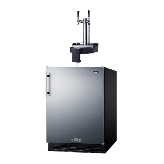
- Page 6 Location of Parts Twin Taps Tower Drip Tray Tower Base Front Base Cover Tube(s) Temperature Control Dial (thermostat) Tube Opening & Interior Light Front Ventilation Slot (Kick Plate) Door Compressor Step Adjustable Leveling Legs Accessories Insulation Plug Tower Front Base Insulation Plug Tower Screw (6)
- Page 7 Installation Instructions Before Using Your Appliance: • Remove the exterior and interior packing. • Before connecting the unit to a power source, let it stand for approximately 2 hours. This will reduce the possibility of a malfunction in the cooling system from handling during transportation.
- Page 8 Electrical Connection: Improper use of the grounded plug can result in the risk of electrical shock. If the power cord is damaged, have it replaced by the manufacturer, its service agent, or similarly qualified persons in order to avoid a hazard. •...
- Page 9 Reversing the Door Swing: NOTE: If your unit’s handle is positioned horizontally, you do not need to change the handle placement. Some units’ doors may not be user reversible. If you find the direction of opening the door of the appliance inconvenient, you can change it. Holes on the opposite side have already been prepared at the factory.
- Page 10 Installing the Casters (optional): 1. Remove everything from the cabinet and lay the unit on a clean, dry, and padded surface. 2. Remove the four feet at the bottom of the unit as shown, install caster into the holes and tighten with a Phillips screwdriver.
- Page 11 Beer Kegs and Keg Tappers: Your kegerator cooler comes with a double tap and will accommodate two “Sixth Barrel” kegs, also known as “sixtels” or “logs”. Each sixtel has a height of 23-3/8” and a diameter of 9-1/4” and hold 5.16 gallons of beer.
- Page 12 Assembling CO Regulator and CO Tank: Note: Your CO cylinder is shipped empty to avoid any possible accidents during transportation. When you purchase the first keg of beer, have your beer distributor fill the CO cylinder. You must read and understand the following procedures for cylinders before installation: 1.
- Page 13 Note: • When replacing the beer keg, first turn off the safety switch on the CO regulator valve and remove the coupler to take out the keg. • When replacing the CO gas cylinder, remember to turn off the main switch of the CO cylinder and the safety switch on the CO regulator valve.
- Page 14 Installing the Cold Brew Coffee Tap Kits: Gas Dual Regulator connected to gas tank Flat Iced Coffee Kits: KitCF KitCFTWIN Nitro-Infused Coffee Kits: KitNCF KitNCFTWIN Combination Flat/Nitro Kit: KitCMTWIN Note: This user manual is prepared for more than one model. Some of the features specified in the manual may not be available in your appliance, but most details should correspond to other kegerators as well.
- Page 15 4. Carefully place the keg inside the kegerator. Attach the coffee tube from the tower to the “out” post of the of the Cornelius keg by pushing the ball lock down over the “out” post until it snaps in place. (See Figure 4) 5.
- Page 16 4. Connect the wine line wingnut to the keg coupler and tighten it. 5. Turn the shut-off lever down to allow the gas to flow. 6. To finalize the connection, pull the black tap handle out and push it down until it clicks securely.
- Page 17 Operating Your Appliance Temperature Control: Your appliance may have a mechanical (dial) or digital thermostat. Listed below are instructions for both mechanical and digital thermostats. Mechanical (dial) Thermostat (on some models): • The interior temperature is controlled with a thermostat knob located inside the unit, towards the upper right-hand corner.
- Page 18 Digital Thermostat (standard on FFAR25L7 and FF31L7 series) ON/OFF POWER To turn the appliance ON or OFF, press the button/mark and hold for 3 seconds. LIGHT To turn the inner light ON and OFF. Used to raise (warm) the set temperature by 1°F/°C. DOWN Used to lower (cool) the set temperature by 1°F/°C.
- Page 19 Care and Maintenance Cleaning Your Appliance: 1. Unplug the appliance, turn the thermostat to STOP (0), and remove all contents, including shelves and crisper. 2. Wash the inside surfaces with a solution of lukewarm water and vinegar. Wipe dry with a clean, soft cloth.
- Page 20 Emptying Beer Line: Residual beer left in the tap line for over an hour may become foamy. When done serving, we recommend emptying the beer line. 1. Shut off the CO tank valve. 2. Close the coupler. 3. Disconnect the beer line hose from the coupler. 4.
- Page 21 Draft Beer Troubleshooting When using this appliance, you may come across some problems that in many cases result from improper handling and can easily be eliminated. Problem Cause Correction Beer is cloudy: The beer in Excessively low temperatures may Drain a few ounces before drinking. the glass appears hazy and cause hazy or cloudy beer, not clear.
- Page 22 General Troubleshooting Problem Cause Correction Power supply is inactive. Check whether the power The appliance fails to supply is active. operate after connecting it Thermostat is set to STOP (0) Adjust the thermostat setting to the power source. on the dial. The door is opened frequently, or it was left open too Keep door closed when it is The compressor is running...
- Page 23 Notes...
- Page 24 Limited Warranty ONE-YEAR LIMITED WARRANTY Within the 48 contiguous United States, for one year from the date of purchase, when this appliance is operated and maintained according to instructions attached to or furnished with the product, warrantor will pay for factory-specified parts and repair labor to correct defects in materials or workmanship. Service must be provided by a designated service company.
Need help?
Do you have a question about the SBC54OSFLTW and is the answer not in the manual?
Questions and answers