Advertisement
Quick Links
Advertisement

Related Manuals for Janome 8002


Summary of Contents for Janome 8002
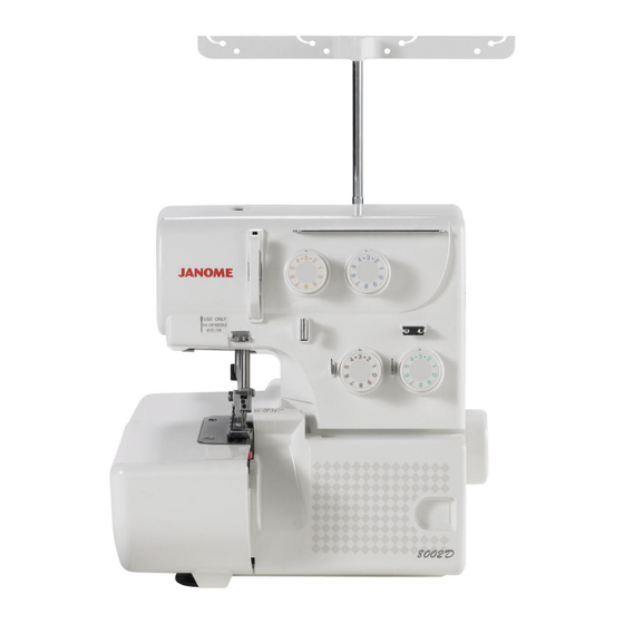
- Page 1 Janome 8002 Service & Parts Manual 8002D Downloaded from Manualsoncd.com...
- Page 2 CONTENTS SERVICE ACCESS FACE PLATE UNIT ......................1 BACK COVER UNIT ......................2 FRONT COVER UNIT .......................3 SIDE COVER UNIT ......................4 MACHINE BASE ........................5 MECHANICAL ADJUSTMENT MACHINE SOCKET......................6 NEEDLE BAR HEIGHT......................7 PRESSER BAR HEIGHT ....................8 FEED DOG HEIGHT......................9 TIMING OF THE NEEDLE AND THE FEED DOG ............10 TIMING OF THE NEEDLE AND THE UPPER KNIFE ............11 HEIGHT OF THE LOWER LOOPER .................12 CLEARANCE BETWEEN THE NEEDLES AND THE LOWER LOOPER...
- Page 3 8002D SERVICE ACCESS FACE PLATE UNIT To remove: 1. Loosen the set screw A and remove the face plate unit. To attach: 2. Fit the U-groove of the face plate between the setscrew A and set plate, put the rib of face plate into the front cover unit and back cover unit and tighten the setscrew.
- Page 4 8002D SERVICE ACCESS BACK COVER UNIT To remove: 1. Remove setscrews A and the spool stand. 2. Remove setscrews B,C and D. 3. Remove the back cover unit. To attach: 4. Put the ribs of back cover into the front cover unit and tighten setscrews B, C and D. 5.
- Page 5 8002D SERVICE ACCESS FRONT COVER UNIT To remove: 1. Remove setscrews A and the looper cover unit. 2. Remove the face plate unit and the back cover unit. 3. Turn the hand wheel toward you with your hand, and set the upper looper at lowest position, and remove setscrews B, C, D,E and the front cover unit.
- Page 6 8002D SERVICE ACCESS SIDE COVER UNIT To remove: 1. Open the side cover unit. Remove the snap ring E-3 and pull out the shaft. To attach: 2. Attach the side cover unit and insert the shaft and attach the snap ring. Side cover unit Snap ring E-3 Shaft...
- Page 7 8002D SERVICE ACCESS MACHINE BASE To remove: 1. Remove setscrews A, B, C, D and two hinge screws E, and remove two base cushions F and washers. 2. Remove the machine base. NOTE: Do not remove the remaining two base cushions. To attach: 3.
- Page 8 8002D MECHANICAL ADJUSTMENT MACHINE SOCKET To remove: 1. Remove the back cover unit. 2. Remove the setscrews (A, B) and the machine socket unit from the motor fixing plate. 3. Remove the two setscrews C, and pull out the cord connectors. To attach: 4.
- Page 9 8002D MECHANICAL ADJUSTMENT NEEDLE BAR HEIGHT Correct Setting: The distance between the tip of needle on the right and the surface of needle plate should be 11.6 to 12.2 mm when the needle bar is at the highest position. To adjust: 1.
- Page 10 8002D MECHANICAL ADJUSTMENT PRESSER BAR HEIGHT Correct Setting: The distance between the surface of needle plate and bottom of presser foot should be 4.7 to 5.3 mm when the presser bar lifter is raised. To adjust: 1. Remove the looper cover unit, face plate unit, back cover unit and front cover unit. 2.
- Page 11 8002D MECHANICAL ADJUSTMENT FEED DOG HEIGHT Correct Setting: When the presser foot is lowered and feed dogs are at their highest position, the distance between the surface of needle plate and bottom of presser foot should be 0.75 to 0.95 mm. To adjust: 1.
- Page 12 8002D MECHANICAL ADJUSTMENT TIMING OF THE NEEDLE AND THE FEED DOG Correct Setting: With the presser foot lowered, the top of the feed dog should be level with the needle plate at the end of feeding movement, when the tip of the right needle is 2-4 mm above the needle plate. Before adjustment, check if the needle bar height and the feed dog height are correct.
- Page 13 8002D MECHANICAL ADJUSTMENT TIMING OF THE NEEDLE AND THE UPPER KNIFE Correct Setting: The upper knife timing is the same as that of the needle bar. In fact, when the needle bar is at highest position, the upper knife should be also at its highest position. To adjust: 1.
- Page 14 8002D MECHANICAL ADJUSTMENT HEIGHT OF THE LOWER LOOPER Correct Setting: The tip of the lower looper is 65.7 mm from the center of the lower shaft as shown below. To adjust: 1. Set the upper knife in down position and loosen the setscrew A. 2.
- Page 15 8002D MECHANICAL ADJUSTMENT CLEARANCE BETWEEN THE NEEDLES AND THE LOWER LOOPER/NEEDLE GUARDS (1 of 3) Correct Setting: Both right and left needles should have an equal clearance from the front edge of the opening on the needle plate. The standard clearance between each needle and the lower looper is 0 mm to 0.5 mm. The standard clearance between each needle and the rear needle guard is 0 mm to 0.2 mm.
- Page 16 8002D MECHANICAL ADJUSTMENT CLEARANCE BETWEEN THE NEEDLES AND THE LOWER LOOPER/NEEDLE GUARDS (2 of 3) 2. Clearance between needles and the lower looper 1. Remove the left needle only. 2. Turn the handweel towards you to bring the tip of the lower looper from the left hand to the rear side of the right needle.
- Page 17 8002D MECHANICAL ADJUSTMENT CLEARANCE BETWEEN THE NEEDLES AND THE LOWER LOOPER/NEEDLE GUARDS (3 of 3) 3. Clearance between needles and the rear needle guard 1. Change the right needle from #11 to #14. 2. Push the front needle guard against the needle to get the clearance between the needle and the lower looper.
- Page 18 8002D MECHANICAL ADJUSTMENT CLEARANCE BETWEEN THE NEEDLES AND THE FIXED NEEDLE GUARD Correct Setting: The clearance between needle and the fixed needle guard should be 0.1 to 0.4 mm. To adjust: 1. Remove the presser foot and the needle plate and lower the needle to its lowest position. 2.
- Page 19 8002D MECHANICAL ADJUSTMENT POSITION OF THE CHAINING FINGER Correct Setting: There should be no gap between the chaining finger and the side of needle plate, and tip of chaining finger should be the same level with the tip of the needle on the needle plate when the needle plate setting knob is set at “S”.
- Page 20 8002D MECHANICAL ADJUSTMENT POSITION OF THE UPPER LOOPER Correct Setting: The clearance between the bottom of the upper looper and the upper looper shaft guide should be 1.6 to 1.8 mm when the upper looper is at its lowest position. The distance between the center of needle on the right and the center of looper eye should be 4.8 to 5.2 mm when the upper looper is at its leftmost position.
- Page 21 8002D MECHANICAL ADJUSTMENT TIMING OF THE NEEDLE AND THE LOWER LOOPER Correct Setting: The tip of the #11 needle on the right should be 2.8 to 3.2 mm above from its lowest position when the tip of the lower looper meets the left side of the needle. To adjust: 1.
- Page 22 8002D MECHANICAL ADJUSTMENT TIMING OF THE UPPER AND LOWER LOOPERS Correct Setting: The distance between the tip of the upper looper and the left side of the lower looper eye should be 0.2 to 1.2 mm when the tip of the upper looper meets the lower edge of the lower looper in its travel from the left to the right as shown in Fig.
- Page 23 8002D MECHANICAL ADJUSTMENT CLEARANCE BETWEEN THE LOOPERS Correct Setting: The clearance between the upper and lower loopers should be 0 to 0.1 mm when the loopers come to the position as shown in Fig. 1. To adjust: 1. Remove the presser foot and needle plate. 2.
- Page 24 8002D MECHANICAL ADJUSTMENT CLEARANCE BETWEEN THE NEEDLE AND THE UPPER LOOPER Correct Setting: When the upper looper meets with needle, the clearance should be: 0 to + 0.1 mm at the needle on the left. -0.05 to + 0.05 mm at the needle on the right. To adjust: 1.
- Page 25 8002D MECHANICAL ADJUSTMENT POSITION OF THE KNIVES Correct Setting: The edge of the lower knife should be level with the surface of needle plate. The front lower corner of the upper knife should be 0.8 to 1.5 mm below the edge of the lower knife when the upper knife is at the lowest position.
- Page 26 8002D MECHANICAL ADJUSTMENT POSITION OF THE LOWER LOOPER THREAD GUIDE Lower Looper Thread Guide (3) Loosen the setscrew A, and adjust the lower looper thread guide (3) so that the hole of the thread guide lines up with the groove of lower looper as shown in Fig. 1. NOTE: After adjustment, make sure that the lower looper thread guide (3) dose not interfere with the arm or feed dog.
- Page 27 8002D MECHANICAL ADJUSTMENT STITCH LENGTH Correct Setting: The actual stitch length should be 2.8 to 3.0 mm when the stitch length dial is set at “ 3 “ and differential feed dial at “ 1.0 “. To adjust: 1. Set the stitch length dial at “ 3 “ and the differential feed dial at “ 1.0 “. 2.
- Page 28 8002D MECHANICAL ADJUSTMENT THREAD TENSION DIALS Thread tension dials are already adjusted for general sewing at factory, however, if you wish stronger or weaker settings for special sewing, it can be altered as follow: To adjust: 1. Pull out the thread tension dial. 2.
- Page 29 8002D MECHANICAL ADJUSTMENT PLAY OF MAIN SHAFT The main shaft should turn smoothly without a detectable lateral play. To adjust: 1. Remove the looper cover unit, and front cover unit. 2. Remove the belt from the handwheel pulley. 3. From the bottom of the machine, loosen setscrews A on the balance weight (right). Press the balance weight to right against the bushing and tighten the setscrews A.
- Page 30 8002D MECHANICAL ADJUSTMENT MOTOR BELT TENSION Correct Setting: To check for proper belt tension, press the belt in the middle of the span lightly with your finger (approximately 300 gr). The belt should bend 5 to 6 mm. To adjust: 1.
- Page 31 8002D OILING Apply a few drops of fine quality sewing machine oil to the parts indicated with arrows. It is recommended to apply oil once a week in normal use, once in ten working-hours in continuous use. Open the side cover and apply oil. Open the looper cover and apply oil.
- Page 32 8002D GAUGES FOR SERVICING Servicing gauge Lower looper height Gauge Needle gauge Thickness O.L G05 No.787-G-01 No.787-G02 No.787-G03 Adjusting gauge O.L G05 This gauge is used for adjusting the following characteristics: (A): Needle bar height (B): Presser bar height 11.4 mm (C): Feed dog height &...
- Page 33 S E R V I C E M A N U A L S E R V I C E M A N U A L S E R V I C E M A N U A L & & &...
- Page 34 8002D PARTS LIST...
- Page 35 8002D PARTS LIST PARTS DESCRIPTION Front cover (unit) 792624149 792051105 Front cover 888261007 Sticker 792020002 U.looper thread guide 785232007 Looper thread guide 792612007 Check spring 785552213 L. needle tension (unit) 785553199 R. needle tension (unit) 792019008 Thread guide U. looper tension (unit) 785554260 785555250 L.
- Page 36 8002D PARTS LIST...
- Page 37 8002D PARTS LIST PARTS DESCRIPTION Spool stand (unit) 789606008 777011003 Spool stand Spool holder 784223105 789607009 Thread guide bar (unit) 000115700 TP screw 4x10 TP screw 4x12 000114802 000001609 Snap ring E-5 Setscrew 4x8 000081005 787197005 Main feed con. arm 2 Main feed con.
- Page 38 8002D PARTS LIST...
- Page 39 8002D PARTS LIST PARTS DESCRIPTION Face plate (unit) 792623001 Face plate 792050001 Thread cutter (unit) 840602006 TP screw 4x10 000115700 Needle plate (unit) 788601000 Eccentric pin 789100007 H. socket screw 3x4 000111902 Flat screw 681009101 Handle set plate 787370004 Setscrew 4x8 000081005 Rear cover (unit) 792615505...
- Page 40 8002D PARTS LIST...
- Page 41 8002D PARTS LIST PARTS DESCRIPTION Setscrew 4x6 000101404 Lamp socket com. (unit) 787510204 Washer 000070300 Lamp socket set plate 789105002 L. cover guide supporter 787153009 M1049A Motor (unit) 777504101 Plug con. rec. (unit) 784128028 Plug. con. receptacle cover 000121905 Tapping screw 4x12 (B) 000104108 Setscrew 4x20 000081005...
- Page 42 8002D PARTS LIST...
- Page 43 8002D PARTS LIST PARTS DESCRIPTION 784027004 Needle bar upper bushing 000111201 H. socket screw 4x4 784028005 Needle bar lower bushing 792601003 Needle bar (unit) 792001007 Needle bar 000101703 Setscrew 4x12 792501002 Needle clamp (unit) 792002008 Needle clamp 888264000 Needle clamp screw 000078320 Setscrew 3x6 792003009...
- Page 44 8002D PARTS LIST...
- Page 45 8002D PARTS LIST PARTS DESCRIPTION Upper looper shaft (unit) 792629007 787111005 Upper looper shaft Upper looper 792055006 000112501 H. socket screw 4x4 U. looper thread guide 784077009 000177205 H. socket screw 3x6 000111304 H. socket screw 5x5 789116006 Upper looper pin 792614009 U.
- Page 46 8002D PARTS LIST...
- Page 47 8002D PARTS LIST PARTS DESCRIPTION 792613008 Chaining finger bracket (unit) 787012005 Chaining finger set plate 789106003 788017003 Chaining finger Needle plate setting knob 787041003 788018004 Chaining finger spring Setscrew 2x4 000074603 000078320 Setscrew 3x6 788019005 Fixed needle guard Chaining finger bracket 788015001 000001609 Snap ring E-5...
- Page 48 8002D PARTS LIST...
- Page 49 8002D PARTS LIST PARTS DESCRIPTION 792604006 Feed bar (unit) 788022001 Main feed bar 788023002 Main feed dog bracket 000104201 Setscrew 3.5x10 787054009 Main feed bar driving arm 787055000 000111902 H. socket screw 3x4 788024003 Sub feed bar 789018007 Sub feed dog 787212007 Sub feed driving arm 787059004...
- Page 50 8002D PARTS LIST...
- Page 51 8002D PARTS LIST PARTS DESCRIPTION Feed adjuster unit 792606008 792012001 Set plate Spring 792011000 000160102 Adjustable nut Differential rod 792014003 785224006 Adjustable screw 792015004 S. length adj. cam 788036008 Dif. adj. cam 792016108 S. length dial Dif. dial 792016153 787262301 Dial cap Spring 787263003...
- Page 52 8002D PARTS LIST...
- Page 53 8002D PARTS LIST PARTS DESCRIPTION 792870108 Accessory set 784860100 Needle set 784810002 Screwdriver (large) 792030005 Screwdriver (small) 624801001 Tweezer 793807004 792800244 Instruction book C - 1028 Foot control Downloaded from Manualsoncd.com...
Need help?
Do you have a question about the 8002 and is the answer not in the manual?
Questions and answers