
Related Manuals for CENTR HYROX NMT

Summary of Contents for CENTR HYROX NMT
- Page 1 Model: NMT ITM. / ART: 80291 USER MANUAL CENTR HYROX NON MOTORIZED TREADMILL IMPORTANT, RETAIN FOR FUTURE REFERENCE: READ CAREFULLY Record Serial Number Here MADE IN CHINA 80291-EN-V2024-08-01...
- Page 3 WELCOME Welcome to Centr and thanks for your purchase. We're happy to have you. Please inspect your product and contact us right away if anything is missing or damaged. Your equipment also comes with access to Centr's digital membership, unlocking tools that will fuel your active lifestyle and well-being.
- Page 5 TABLE OF CONTENTS PRODUCT WARRANTY..................3 IMPORTANT SAFETY INSTRUCTIONS............6 WARNING AND SERIAL NUMBER LABELS..........9 USE OF RESISTANCE LEVER................10 HARDWARE PACK.....................12 ASSEMBLY......................14 FEATURES OVERVIEW..................26 CONSOLE OPERATION...................27 MAINTENANCE AND CARE................32 80291-EN-V2024-08-01 Pg. 5...
- Page 6 Never Insert Objects Into Any Openings In This Treadmill. If An Object Has Been Dropped In The Treadmill Try To Carefully Retrieve It. If The Item Cannot Be Reached, Contact Centr Customer Service. To Carefully Retrieve It. If The Item Cannot Be Reached, Contact Centr Customer Service.
- Page 7 Over The Age Of 35 Or Persons With Pre-Existing Health Problems. Read All Instructions Before Using Any Fitness Equipment. Centr, Llc. Does Not Assume Any Responsibility For Personal Injury Or Property Damage Sustained By Or Through The Use Of This Product.
- Page 9 WARNING AND SERIAL NUMBER LABELS 20 MM 80292-V2024-08-01 64.4 MM 80294-V2024-08-02 Manufacture according to MFG-001 specification, supplied by CENTR Engineering. WARNING The possibility of serious injuries or death may occur if caution is not used. Ensure safety by following these...
- Page 10 SPACE REQUIREMENTS This treadmill requires a minimum amount of floor space to safely operate. Keep a minimum open area of 2 m (78 in) behind the treadmill, and 0.5 m (20 in) on both sides. 0.5 m 20 in 0.3 m 12 in 108 cm 42.5 in...
- Page 11 80291-EN-V2024-08-01 Pg. 11...
- Page 12 HARDWARE PACK (NOT TO SCALE) HARDWARE STEP 1 (Hardware pre-assembled) STEP 2A (Hardware pre-assembled) 10 X SCREW, M4. X 15 STEP 2B (Hardware pre-assembled) 14 X SCREW, M5 X 40 STEP 3 14 X SCREW, M4 X 10 STEP 4 (Hardware pre-assembled) 8 X BOLT, M8 X 20 8 X SPRING WASHER, 8 8 X FLAT WASHER, 8.4...
- Page 13 171 mm HARDWARE 1 x PHILLIPS SCREWDRIVER (A) 201 m 1 x 4 mm HEX KEY (B) 80291-EN-V2024-08-01 Pg. 13...
- Page 14 ASSEMBLY WARNING IT IS RECOMMENDED TO HAVE AT LEAST 2 PEOPLE FOR UNBOXING AND ASSEMBLING THE TREADMILL. NOTE: Please remove nut and washer from bolt, prior to assembling. STEP 1: Using a Phillips Screwdriver (A), remove the 5 screws (M4 x 15) securing the Right (1) and 5 screws (M4 x15) securing the Left Front Cover (2) panels to the Base Frame Assembly (3).
- Page 15 STEP 2A: Using a 4mm Hex Key (B), remove the screws (M5 x 40) that attach the Right (4) and Left Foot Covers (5) to the Base Frame Assembly (3). Set the hardware and covers aside in a safe place. HARDWARE REQUIRED 14 X SCREW, M5 X 40 80291-EN-V2024-08-01...
- Page 16 Step 2B: Use a Phillips Screwdriver (A) to remove the screws (m4 x 10) securing the Side Covers (6), and place these screws and covers safely out of the assembly area. HARDWARE REQUIRED 14 X SCREW, M4 X 10 Pg. 16 80291-EN-V2024-08-01...
- Page 17 Step 3: Remove the cables from the lower end of the Right Upright (7) and route cable through the Plate Base (8). Then, attach the right upright to the Base Frame Assembly (3), but do not fully tighten the hardware at this stage. Secure cable to the plate base using Two Locking Nuts (9) and Needle-Nosed Pliers (C), ensuring both locking nuts are on the far side of the plate base.
- Page 18 Step 4: After you have completed installing the right and the left upright rails, on the right side of the treadmill remove the hardware from the U-Joint Bracket (10). Attach and seal the End Of Cable (11) to the U-Joint Bracket (10) using a cotter pin.
- Page 19 Step 5: Route the Speed Sensor Cable (15) coming out of the base frame assembly and connect it to the Speed Sensor Cable (16) coming out of the Right Upright Rail (7). Ensure not to cut or crimp the cables. NOTE: After you have completed connecting the cable and the wire, cut the tie wrap used to hold the plate holding...
- Page 20 Step 6A: Pull one Cable Connector (17) from the Front Handrail (20) and another Cable Connector (18) from Console (19). Route the cables through the Front Handrail (20) and connect the cables. Push the cables into the front handrail without cutting or crimping them. Attach the Console (19) to the front handrail using the hardware and put the Back Cover (21) to cover the bracket.
- Page 21 Warning Recommended to have at least 2 people for this step. Step 6B: Gently pull the Cable Connectors (22, 23) from the Front Handrail Assembly (20) and the Right Upright (7). With support, connect the cables and push them inside the right upright. Slide the front handrail assembly between the uprights, carefully push the cables inside the Right Upright (7), and secure the assembly to the uprights by fastening the hardware mentioned below.
- Page 22 Step 7: Slide the Junction Cover (24) to the Front Handrail Assembly (20), and attach it using the hardware mentioned below. NOTE: Follow same steps to attach the junction cover on other rail. (24) (20) HARDWARE REQUIRED 4 X SCREW, M4 X 15 Pg.
- Page 23 Step 8: Reattach the Side Covers (6), Foot Covers (4,5), and the Front Cover Panels (1,2) to the Base Frame Assembly (3) in that order. Refer to steps 2B, 2A, 1 and use the previously removed screws to secure the above. Ensure each component is properly aligned and tightened for a secure fit. HARDWARE REQUIRED 14 X SCREW, M4 X 10 SIDE COVERS (6)
- Page 24 Step 9: Attach the Upright Covers (25) to both the uprights, attach the Cell Phone Holder (26), and the Bottle Holder (27) by sliding it into the grooves on the left upright. (26) (27) NOTE: Follow same steps to attach the upright cover on the other rail.
- Page 25 Step 10: Slide the Handle Assembly (28) into the rear of the base frame assembly and secure it with the indicated hardware. (28) HARDWARE REQUIRED 2 X NUT, M10 2 X FLAT WASHER, 10 80291-EN-V2024-08-01 Pg. 25...
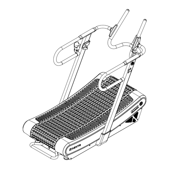
- Page 26 FEATURE OVERVIEW DISPLAY CONSOLE PHONE HOLDER CUP HOLDER HAND RAILS RUNNING DECK RESISTANCE ARM TRANSPORT WHEELS TRANSPORT SIDE PLATFORM HANDLE Pg. 26 80291-EN-V2024-08-01...
- Page 27 BEFORE YOU BEGIN This treadmill is built for optimum safety. However, certain precautions apply whenever you operate a piece of exercise equipment. WARNING Before using this treadmill, all users must read, understand, and carefully follow all warnings, instructions, and procedures on the treadmill and in this user manual. The user is required to perform a complete visual inspection, and test of the features and functions of the assembled treadmill prior to use.
- Page 28 DISPLAY INTERFACE OPERATION Motion data display indicator Bluetooth app connection Battery level display Program goal achieved” indicator Speed rpm indicator Speed & motion programming Training tracking light/tracker. There are 44 cells in Motion total, each cell program represents 10 rpm pattern Exercise time &...
- Page 29 DETAILS OF DISPLAY PATTERN APP BLUETOOTH CONNECTION TARGET AND ACTUAL When no light is flashing, it means INDICATOR that the bluetooth system is off. When flashing, it indicates in the bluetooth device search. According to the usage mode, the movement When always bright, it means device data in different modes: connected.
- Page 30 NOTE: Console will come to standby 1 minute after coming to a hault. If the pause detects rpm greater than 25 during motion, it returns to the screen before pressing pause. The screen will go to sleep 2 mins after coming to stop. Switch average and Start, pause and Select program and...
- Page 31 WIRELESS HEART RATE MONITORING DISPLAY WHEN STARTING THE EXERCISE PROGRAM AND STARTING THE EXERCISE, WEAR THE STANDARD HEART RATE BAND (5.3K HEART RATE BAND, SUCH AS PLA WIRELESS HEART RATE BAND, ETC.), AND THE ELECTRONIC METER CAN DETECT AND DISPLAY THE HEART RATE VALUE.
- Page 32 MAINTENANCE AND CARE General cleaning will help prolong the life and performance of the treadmill. • Keep the treadmill clean and maintained by dusting the components on a regular basis. • Clean the side platforms and the visible portion of the running deck to prevent debris from accumulating underneath the running belt.
- Page 33 centr.com...
Need help?
Do you have a question about the HYROX NMT and is the answer not in the manual?
Questions and answers