
Related Manuals for Rize Home 32012


Summary of Contents for Rize Home 32012
- Page 1 Revision Number: 01 32012 DAYBED E 1 1 9 0 0 6 3 , E 1 1 9 0 0 7 0 , E 1 1 9 0 0 8 4 E 1 1 9 0 0 9 1 , E 1 1 9 0 1 0 5 , E 1 1 9 0 1 1 2...
- Page 2 CAUTION: DO NOT SLIDE BED; PICK BED UP TO REPOSITION/LOCATE IT UPON COMPLETING ASSEMBLY ( L ) ( R ) Components Hardware 1 set Upward Assembly 1 set 1 pc M8X20 M6X35 M6X50 M4X32 M4X16 1 pc 8 pcs 4 pcs 52 pcs 24 pcs 17 pcs...
- Page 3 CAUTION: Do not a empt to slide the bed once it is fully assembled. To avoid structural damage while moving your assembled bed, any ma ress and bedding should be removed from the bedframe. Then the bedframe should be li ed and carried (not slid) to your desired loca on. When placing furniture on non-carpeted flooring, we recommend the use of floor protec on such as an area rug or furniture pads.
- Page 4 ( Back) 8 pcs M8X20 (Le ) ( Front ) ( Back) Thread “J” bolts into the holes in the arms”A”. Do not ghten bolts. These will be ghtened in later steps. (Right) ( Front ) Hang the hooks at the ends of the side rails “B” onto the “J”...
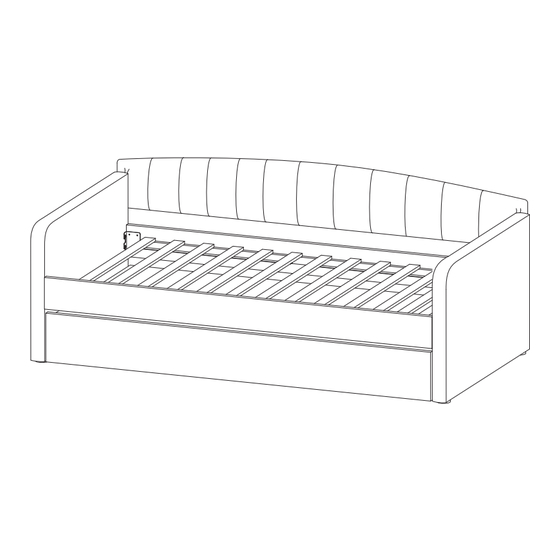
- Page 5 ( Front ) M6X50 4 pcs (Le ) ( Back) (Right) A ach “P”and “O” washers to “M” bolt. Connect the back panel “C” to back of arms “A”. Use the bolts to a ach. Extend the slats “E”, place the slats into the frame of the daybed as shown.
- Page 6 Assemble the trundle slats system by a aching the slats “F” to the supports “G” . First, extend the slats. Then, line up the holes in the slats “F” with the holes in the supports “G”. A ach “P” M6X35 9 pcs and “O”...
- Page 7 M6X35 4 pcs Line up the holes in the cleats “H” with the holes in the front panel “D”. A ach “P” and “O” washers to “K” bolt. Use bolts through the holes to connect them together. M6X35 4 pcs Line up the holes in the slats “F”...
- Page 8 Use screwdriver to M4X32 20 pcs install“N” screws into supports “ G” Push the trundle into the place under the daybed You’re all finished!
Need help?
Do you have a question about the 32012 and is the answer not in the manual?
Questions and answers