Advertisement
Attention and installation
Maintenance
- Disconnect from mains before starting maintenance operation.
- The lamps should be kept dry to avoid working in wet environments.
- Intermittent use would effectively extend the lamp life.
- In order to obtain good ventilation and lighting effects, to pay attention to regular cleaning fan, fan network, and lens.
- Don't use alcohol and other organic solvents to clean the housing, so as to avoid injury.
Attention
- This lighting fixture is for professional use only.
- Ensure that the power source has a proper ground connection before using the lamp.
- Don't place this product in a place that is easy to loosen or vibrate.
- In the process of using, if the lamp is abnormal, stop using the lamp in time.
- In order to ensure the service life of the product, the product should not be placed in a damp or leaking place, and the temperature should not exceed 60 degrees Above environmental work.
- When the bulb is used, the change of supply voltage should not exceed ±10%, the voltage is too high, which will shorten the life of the bulb, and if the voltage is too low, it will affect the light color of the bulb.
- After power outage, it takes 20 minutes to fully cool the lamp before it can be powered on again.
- The lamp rotating and pasting accessories must be checked regularly, loosened, shaken and strengthened in time to prevent accidents.
- Please read this note carefully to ensure the normal use of the product.
Product presentation
- Light source power: 260W;
- Power supply: AC 200V~240V/50~60Hz;
- Color wheel: Each color wheel consists of 13 color slices + white light;
- Gobo wheel: 18 gobos;
- 540° of pan movement, 270° of tilt movement.
- Intelligent thermal protection protection;
- Control mode: DMX512/master-slave/Auto-run;
- IP20 protection grades.
DMX connection
See figure 1.
The fixture is equipped with both 3-pin or 5-pin XLR sockets for DMX input and output. Please use the twisted pair signal line specially shielded for DMX 512. The signal line is generally connected at a distance of 150m. When the long distance signal is transmitted, the DMX512 signal amplifier must be added.
Use a shielded twisted pair signal line to connect from the controller's DMX output to the DMX input of the first device, And connect from the DMX output of the first device to the DMX input of the second device, by parity of reasoning, Until all the lamps and lanterns are connected, Then install a terminal plug on the last connecting lamp output 3 core Jack of each link.(Weld a 4/1 W,120 Ω resistor between the 2 and 3 pins.)


Important tip: the line cannot contact each other or with the metal shell.
- The method of calculating the initial address code of fixture:
The starting address code of the current lamp is equal to (the starting address code of the previous lamp)+(number of channels of the lamp) stating:- the initial address code value of the first lamp is A001.
- The number of basic channels for the controller shall be greater than or equal to the total number of channels used in fixture.
- Note: when using any controller, each lamp must have its own starting address code, if the first lamp initial address code set A001,the lamp path number of 16; Then the starting address code for the second lamp is set to A017; the starting address code for the third lamp is set to A033; and so on.(this setup also needs to be determined by different control stations)
Fixtures installation
Lamps can be placed horizontally, obliquely and upside down. Always pay attention to the installation method when hanging obliquely and upside down.
As shown in the figure 2, To ensuring safety, Before locating the lamps, to ensure the stability of the installation place, In upside down installation must be Keep the lamp don't drop the support frame, Prevent lamps from falling and sliding, need to use safety rope through support frame and lamp handle.
Pedestrians are forbidden to pass under the lamp during installation and commissioning, check safety rope regularly for wear and tear, hook screws are No loosening.
We shall not bear any responsibility for all the consequences arising from the fall of the lamp due to the unstable installation of the hanging.

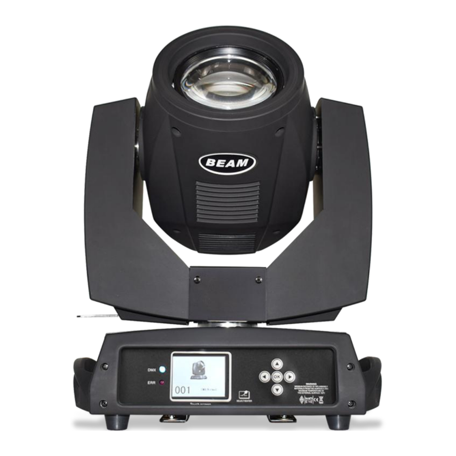
CONTROL PANEL
Button description

See figure 3.
Menu description

See figure 4.
Manually
This interface is used to control the current lamps, at the same time get into the master status(not receiving DMX signal, send DMX signal to slave through bus. Manual Menu will show the 16 or 20 channels according to the standard 16 or extended 20 channel setting in Setting Menu.
| Options | Description | |
| 1CH. Color Wheel | 0~255 | Press "OK" button into Edit Mode. Now the hundred-bit is selected, press "UP","DOWN" to change the channel value. Press "OK" again to choose the decade-bit to edit. Press "OK" once again to choose the unit-bit, again to quit the Edit Mode. |
| ...... | 0~255 | |
| 14CH. Marco Function | 0~255 | |
| 15CH. Reset | The Confirmation dialog will show after pressing "OK" button, press "OK" again to go into the Restore interface, all the motors reset. | |
| 16CH. Lamps Control | on | |
| off | ||
| 17CH. Empty | 0~255 | Show when the Channel Mode is set to "Extended CH20" |
| 18CH. The Color Wheel Speed | 0~255 | Show when the Channel Mode is set to "Extended CH20" |
| 19CH. dimmer-prism-atomizer speed | 0~255 | Show when the Channel Mode is set to "Extended CH20" |
| 20CH. gobo speed | 0~255 | Show when the Channel Mode is set to "Extended CH20" |
Setting
| Options | Description | |
| Run Mode | DMX | Status of Slave: receive the DMX signal from the main console or master |
| AUTO 1 | Demonstration of AUTO run effect. Status of Master: AUTO and send DMX signal to slave | |
| AUTO 2 | ||
| Random | ||
| Sound | ||
| DMX Address | 1~512 | The yellow arrow was selected, Press "OK" button into Edit Mode, when the font color is red, press "UP or "DOWN" to change the address code, Press "OK" again to save and exit the edit. |
| Channel Mode | Standard 16CH | Standard 16 channel mode, 17~20 channels are useless |
| Extended 20CH | Extended 20 channel mode, 17~20 channels control speed(see the channel list) | |
| Pan Invert | OFF | Exchange start and end points when open, The default is OFF |
| ON | ||
| Tilt Invert | OFF | Exchange start and end points when open, The default is OFF |
| ON | ||
| Pan-Tilt Swap | OFF | |
| ON | Invert channels of Pan-Tilt(including fine-tuning) | |
| Pan-Tilt Encoder | ON | Use encoder (optocoupler)to estimate the wrong step and right the wrong position |
| OFF | Don't use encoder(optocoupler) to right the position | |
| DMX Signal | KEEP | Keep going as this status |
| CLEAR | Motor return, stop running. | |
| Display | OFF | Always bright |
| ON | screen saver | |
| Lamp on after startup | off | Reset after power on, not turn on the lamp(need to use the Menu or console to turn on lamps manually) |
| on | Automatically turn on the lamps after power on, and reset only after turning on the lamps successfully | |
| Linear Change of Color Wheel | ON | Linear change of color wheel |
| OFF | No linear change of color wheel, half color change | |
| Restore Default Setting | The Confirmation dialog will show after pressing "OK" button, press "OK" again to restore the default setting. | |
System
| Options | Descriptions | |
| DIS Ver | Display version | |
| MT Ver | Motor version | |
| Reset Calibration | Pan calibration | After entering into the sub-interface, adjust the rest positions of motors in Pan and Tilt to make up the error in hardware installations, adjustment range is -128~+127, +0 means no change. |
| Tilt calibration | ||
| Color wheel calibration | ||
| Gobo calibration | ||
| Focus calibration | ||
| Dimmer calibration | ||
| Prism 1 calibration | ||
| Prism 2 calibration | ||
| Frost calibration | ||
| Rainbow lens calibration | ||
| Sensor Monitoring | Pan Hall status | 0 is detected, otherwise 1 |
| Tilt Hall status | 0 is detected, otherwise 1 | |
| Color Wheel Hall status | 0 is detected, otherwise 1 | |
| Gobo Hall Status | 0 is detected, otherwise 1 | |
| Focus Hall status | 0 is detected, otherwise 1 | |
| Pan encoding disk status | 2 digits, each digit correspond to a photoelectric switcher in encoding disk | |
| Tilt encoding disk status | 2 digits, each digit correspond to a photoelectric switcher in encoding disk | |
| Pan encoding step value | Positive direction, step value increases, negative direction, step value decreases. The same of values are normal every time when they go to a certain point. | |
| Tilt encoding step value | Positive direction, step value increases, negative direction, step value decreases. The same of values are normal every time when they go to a certain point. | |
| System Errors Log | If red ERR is on, it means lamp runs error, go into sub-interface to check the detail. You can press "Clear" button to clear the log. | |
| DMX Channel value | Go into sub-interface, show the channel value using number and percent | |
| Error | Descriptions | |
| MT Board Connect Fail | The driver board has no response. The line connecting the display board and UART communication lines in driver board, or there's something wrong with driver board. | |
| Pan reset fail | Pan photoelectric switch, or Pan motor's problem | |
| Tilt reset fail | Tilt photoelectric switch, or Tilt motor's problem | |
| X-axis Hall Error (Pan Hall error) | Tilt hall error | |
| Y-axis Hall Error (Tilt Hall error) | Tilt hall error | |
| Motor Colour reset fail | Color Wheel hall, or Color wheel motor's problem | |
| Gobo Hall reset fail (Motor Gobo reset fail) | Gobo Hall, or Motor Gobo's problem | |
| Motor Focus reset fail | Focusing Hal, or Focusing Motor's Problem | |
| Lamp control fail | Lamps on/off fail, lighter or the lamp's problem | |
| lamp hours too long, please replace | Total time of lamp on is over the max value in Advanced setting, to remind the user to replace the lamp. After replace, clear the time value of lamp on in Advanced setting to record from start. | |
CHANNEL FUNCTION
Channel list
| Channel | CHANNEL MODE | |
| 16 | 20 | |
| 1 | COLOUR WHEEL | COLOUR WHEEL |
| 2 | STROBE | STROBE |
| 3 | DIMMER | DIMMER |
| 4 | STATIC GOBO CHANGE | STATIC GOBO CHANGE |
| 5 | PRISM INSERTION | PRISM INSERTION |
| 6 | PRISM ROTATION | PRISM ROTATION |
| 7 | EMPTY | EMPTY |
| 8 | FROST | FROST |
| 9 | FOCUS | FOCUS |
| 10 | PAN | PAN |
| 11 | PAN FINE | PAN FINE |
| 12 | TILT | TILT |
| 13 | TILT FINE | TILT FINE |
| 14 | MARCO FUNCTION | MARCO FUNCTION |
| 15 | RESET | RESET |
| 16 | LAMP CONTROL | LAMP CONTROL |
| 17 | PAN-TILT TIME | |
| 18 | COLOUR TIME | |
| 19 | DIMMER-PRISM-FROST TIME | |
| 20 | GOBO TIME | |
Detailed numerical:


TROUBLESHOOTING
It is recommended some solution for some normal trouble shooting. Any inextricable problems should always be handling by the professional person. Disconnect the power supply before maintenance the light.
-
LAMP OFF
- Please check if install the suitable voltage
- Please check whether the power supply will reach the end of their life can explode, please replace a same description power supply.
- Please check if the power supply is enough.
- Please check whether the DMX 512 controller pass the "turn on" order.
-
The unit couldn't accept the control order
- Please check the start code address and the function option are correct.
- Please check whether the communicate control cable is on good connection or the cable is too long or interrupt.
- Please check the control system is not valid, check the signal amplifier of chain connected is valid.
- Please check whether the communicate cable is too long or the other equipment is mutually conjugate.
- Please arrange the wire well, shorter the signal cable, put the high voltage cable and low voltage cable separately.
- Add the signal amplifying isolator.
- Signal cable is used the excellent screening doublet.
- The end of the light end and the end resistance(120OHM).
-
The light can't move
- Please check if the power supply is suitable for the light voltage data.
- Please check the light if they are deformation, inside parts is broken, become wet etc will lead the loose contact.
- Please check the if the inside lead wire and the connector is loose.
- Please check the electric parts(such as the transformer, PCB board, controller) is short-circuit or burn down.
-
The pan&tilt couldn't work normally on working
- Please check according to the above step by step.
- Please check the belt of the X/Y is broken.
- Please check the X/Y direction data to the receiver is damage.
- Re-projector reset.
Documents / ResourcesDownload manual
Here you can download full pdf version of manual, it may contain additional safety instructions, warranty information, FCC rules, etc.
Advertisement


Need help?
Do you have a question about the 7R and is the answer not in the manual?
Questions and answers