Bosch Compress 3800i AW (CS3800iAW AWM 13) Manual
- Installation instructions manual (32 pages)
Advertisement
- 1 Product Information
- 2 Preconditions for installation
- 3 Installation
- 4 Hydraulic connection
- 5 Electrical connection
- 6 Outdoor temperature sensor T1
- 7 Flow temperature sensor T0
- 8 Commissioning
- 9 Decommissioning
- 10 Inspection and maintenance
- 11 Refrigerant circuit
- 12 Safety instructions
- 13 Documents / Resources
Product Information
Standard delivery

Fig. 1 Standard delivery
- Indoor unit
- Particle filter
- Documentation
- Outside temperature sensor
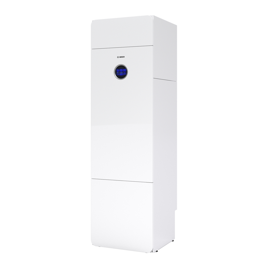
Information about the indoor unit
The indoor units CS3800i AWM 13 are intended for connection to AW O- S and AW O-T outdoor units. CS3800i AWM 13 has an integrated booster heater, DHW cylinder and a small size buffer cylinder.
Dimensions and minimum clearances
 There should be at least 50 mm between the indoor unit's sides and other fixed installations (walls, sinks, etc.). Ideal positioning is by an external wall or a partition wall.

Fig. 2 Minimum distance (mm)
")
Fig. 3 Dimensions (mm)

Fig. 4 Dimensions, connections, top view
Product overview
Front view without cover

Fig. 5 Front view
- Manual purge valve
- Electric heater
- Buffer cylinder
- Heat carrier pump PC0
- Manometer
- Inspection hatch
- Anode
- Drain valve DHW cylinder
- Drain valve heating water (CH)
- Manual purge valve
- Expansion vessel
- Heating system primary pump PC1
- Type plate*
*The type plate of the indoor unit can be found inside of the appliance. It contains information on the part number and serial number and also the date of manufacture of the device.
Roof panel

Fig. 6 Product overview top view
- Flow to heating system
- DHW outlet connection
- Cold water inlet connection
- Heat transfer medium out (to the heat pump)
- Heat transfer medium in (from heat pump)
- Label for pipe connections
- Return from heating system
- DHW circulation connection (accessory)
Regulations
To make sure that the product is installed and operating correctly, comply with the national and regional regulations, as well as all the technical rules and guidelines.
Transport and storage
The indoor unit must always be transported and stored in an upright position. If needed, it may be leaned temporarily.
The indoor unit may not be stored or transported at temperatures below – 10°C.
Accessories
Required system components
The following components are not included in the standard delivery but are required for the initial startup and operation of the system.
Heating system:
- Automatic air vent valve [VL1]
- Magnetite filter/separator (not necessary if the system only consists of newly installed underfloor heating)
- Equipment for filling of heating and DHW system
- Non-return valve if the cooling mode is to be used.
A non-return valve may be necessary to prevent self-circulation in the heating system. This can mainly arise in the following situations:
- Heating system with radiators.
- The indoor unit is installed below the heating system (basement or multi-story building).
- The outdoor unit is installed on the same height or below the indoor unit.
Hot tap water:
- Non-return valve for incoming cold water
- Pressure relief valve cold water
Heat pump:
- Manual valve [VC4] between the indoor unit and the heat pump. The valve is used when filling and venting the system. It is not allowed to completely disconnect the heat pump from the indoor unit, therefore only one valve is required.
Optional accessories
The following accessories can be added on and are not required for operation of the system.
- Room controller
- Thermostatic valve hot water
- Connect-Key K30RF
- DHW circulation pump
- Safety thermostat for under floor heating
- Condensation sensor for non -condensing cooling mode
Room controller
For higher system efficiency, it is recommended to integrate room controllers instead of thermostatic radiator valves in the heating system. The room controller provides feedback that will automatically adjust the heating curve to control the room temperature. This ensures that the heat pump will only operate when there is heating or cooling demand.
Preconditions for installation
General notes
 NOTICE
System damage due to objects in the pipes!
Objects in the pipes will decrease the flow and cause operational problems.
- Flush the pipework to remove foreign objects.
Placement of the indoor unit
- The indoor unit is placed in the building. The pipework between the heat pump and indoor unit must be as short as possible. Use insulated pipes.
- The installation location for the indoor unit must have a drain.
- The ambient temperature around the indoor unit shall be between +10°C and +35°C.
Fill and top-up water
Water quality for potable water (DHW)
The stainless steel integrated domestic hot water cylinder is constructed to heat and store potable water. Follow country-specific regulations, directives and standards for drinking water. The water quality in the cylinder has to comply with the framework of the EU directive 2020/ 2184.
The following values must be emphasized:
Table 1 Boundary conditions for potable water
| Water quality | Unit | Value |
| Conductivity | μS/cm | ≥ 130...<= 1500 |
| pH | - | ≥ 6,5... ≤ 9,5 |
| Water hardness | ppm CaCO3 grain/US gallon 0dH 0fH | > 36 >2,1 >2 >3,6 |
Installation
Safety instructions

Risk of injury!
During transport and installation there is a risk of crushing injury. During maintenance, internal parts of the appliance may become hot.
- The installer is obliged to wear gloves during transport, installation and maintenance.
NOTICE
Risk of material damage!
Particles in the pipework of the heating system can damage the heat pump system.
- Installation of a particle filter is mandatory for all systems.
Check size of expansion vessel
Characteristic diagram for expansion vessel (17 l)
The following graph can be used to estimate whether the installed expansion vessel will be sufficient or whether an additional expansion vessel will be required (not for underfloor heating).
For the curves shown, the following parameters were taken into account:
- 1% water seal in the expansion vessel or 20% of the rated volume in the expansion vessel
- Working pressure differential of the pressure relief valve of 0.5 bar
- Pre-charge pressure of the expansion vessel corresponds to the static system height above the appliance.
- Max. operating pressure: 3 bar

Fig. 7 Curves for the expansion vessel (17 l)
Legend to fig. 7:
- Pre-charge pressure 0.5 bar
- Pre-charge pressure 0.75 bar (default setting)
- Pre-charge pressure 1.0 bar
- Pre-charge pressure 1.2 bar
- Pre-charge pressure 1.3 bar
A Operating capacity of the expansion vessel
B Additional expansion vessel required
T Flow temperature
V System content in litres
- If results are borderline: determine precise vessel size in accordance with country-specific regulations.
- If the intersection is on the right beside the curve: install an additional expansion vessel.
Prepatory work
- Run the connector pipes for the heating system and cold water/DHW in the building up to the installation location of the indoor unit.
- Mount and align adjustable feet provided so that the indoor unit is level.
Remove the front

Fig. 8 Remove the front
Installation checklist
Each installation is unique. The following checklist provides a general description of how the installation should be performed.
- Install the fill valve.
- Install the non-return valve (if the cooling mode is to be used).
- Install the leakage drain hoses.
- Connect heat pump to the indoor unit.
- Connect the indoor unit to the heating system.
- Install particle filter and magnetite separator (magnetite separator is only optional for new building with only under-floor heating system).
- Connect the tap water to the indoor unit and the pressure-relief valve.
- Mount the outside temperature sensor and any room controller.
- Connect the CAN-BUS cable to the heat pump and the indoor unit.
- Install any accessories.
- Connect the EMS-BUS cable to accessories if needed.
- Fill and vent the DHW cylinder.
- Fill and vent the heating system before commissioning.
- Establish the electrical connection of the system.
- Commission the system.
- Vent the heating system also during the commissioning.
Sizing the DHW circulation lines
If the following conditions are observed, an extensive calculation can be omitted for one to four-family houses:
- DHW circulation, single and common lines with an internal diameter of at least 10 mm
- DHW circulation pump DN 15 with a flow max. of at most 200 l/h and a flow pressure of 100 mbar
- Length of the DHW lines max. 30 m
- Length of the DHW circulation line max. 20 m
- The temperature drop must not exceed 5 K
To easily observe these specifications:
- Install a control valve with thermometer.
To save electrical and thermal energy, do not run the DHW circulation pump continuously.
Installation of accessories
Placement of the Connect-Key K30RF
You can find information on the Connect-Key K30RF, the WIFI connection, establishing the connection with the Internet and integration of accessories in the corresponding app and in the packaging of the Connect-Key K30RF.
- Place the module in the holder (→[1], figure 9). A LED will flash when properly inserted.
![]()
Fig. 9 Connect-Key K30RF placement

External connections
Maximum load at relay outputs: 5A, 400W, cos φ>0,4. At a higher load an intermediate relay must be installed.
- Relay output PK2 is active in cooling mode. Possible application areas:
- Changing between cooling/heating for fan coils. This requires that the fan convector's control unit has this feature.
- Pump control in a separate circuit which is exclusively intended for cooling mode.
- Underfloor heating system control in damp rooms.
Safety thermostat
In some countries, a safety thermostat is required to be installed in under floor heating circuits. The safety temperature limiter is connected to external input 3. Set the operation for external input (→ control unit manual).
It is recommended to use a safety thermostat with automatic reset.
If the switching temperature of the safety thermostat is set too low or the thermostat is placed too close to the indoor unit, this may lead to a temporary blockage of the heating circuit pump PC1 and the heat sources after DHW charging.
- Set a temperature that is suited for the floor.
- Place the thermostat at least >1m from the indoor unit.
Summary alarm (with accessory module)
The appliance has no output for summary alarm. If there is a need for a summary alarm this has to be accomplished by installing of an accessory module MU100.
- Install the accessory module and do the settings for summary alarm before commissioning of the system (→ manual for accessory module).
Installation with cooling mode
Condensing cooling mode with fan convectors
It is mandatory to install a non-return valve to use the cooling mode (→ see required accessories in "Required system components" chapter).
NOTICE
Material damage due to moisture!
Without full insulation against condensation, moisture can attack neighbouring materials.
- Provide all pipes and connections up to the fan convector with condensation insulation.
- Use an insulating material designed for cooling systems with condensate formation.
- Connect condensate pipes to the drain.
- Do not use a condensation sensor when in cooling mode below the dew point.
- Do not use a room temperature-dependent control unit with integrated condensation sensor when in cooling mode below the dew point.
When exclusively fan convectors with a drain and insulated pipes are used, the flow temperature can be reduced to 7°C.
NOTICE
Thermal breach!
When the cooling mode is used below dew point, the resulting condensation may damage other components of the appliance.
- To avoid thermal breach, the installer should insulate the thermal pipes (see → Fig. 10 "Pipes that require insulation, when the cooling mode is used below dew point").

Fig. 10 Pipes that require insulation, when the cooling mode is used below dew point
Hydraulic connection
NOTICE
Residue in the pipework can damage the system.
Solids, metal/plastic filings, flux and thread tape residue and similar material can get stuck in pumps, valves and heat exchangers.
- Keep foreign bodies from entering the pipework.
- Do not leave pipe parts and connections directly on the ground.
- When deburring, make sure that no residue remains in the pipe.
- Before connecting the heat pump and indoor unit, rinse the pipe system to remove any foreign bodies.
If Installation is done without a heating circuit, the pipes needs to be capped.
- Put caps on the flow- and return pipes to the heating system.
In accordance with good installer practice it may be required to install additional air vent valves at the highest point of installation.
Insulation
NOTICE
Material damage due to frost and UV radiation!
In case of a power outage the water in the pipes may freeze. The insulation may become brittle due to UV radiation and crack after some time.
- Use insulation with a thickness of at least 19 mm for pipework and connections outdoors.
- Install drain valves so that the water can be drained out of the lines to and from the heat pump if it is not going to be used for some time or if there is a risk of frost.
- Use UV and moisture-resistant insulation.
- Insulate the wall insertion.
- In buildings, use insulation with a thickness of at least 12 mm for pipework. This is also important for safe and efficient DHW mode.
All heat-conducting pipework must be provided with suitable thermal insulation according to applicable regulations. In cooling mode, all connections and lines must be insulated according to applicable standards to prevent condensation.
Pipe connections, general
Dimension the pipes according to the instructions (→Table 2).
- Avoid splicing the heat transfer pipes to minimise pressure drop.
- PEX pipes are recommended for all connections between the heat pump and indoor unit.
- Use only material (pipes and connections) from the same PEX distributor to avoid leakage.
- Pre-insulated AluPEX pipes are recommended as they make installation easier and prevent gaps in the insulation. PEX or AluPEX pipes also dampen vibrations and insulate against noise transfer to the heating system.
If a material other than PEX is used, the following is required:
- Install a particulate filter intended for outdoor use on the return line of the heat pump, directly at the heat exchanger.
- Insulate the particulate filter as well as the other connections.

Fig. 11 Pipe length A
- Indoor unit, floor standing
- Heat Pump
Table 2 Pipe dimensions and maximum pipe lengths (one-way) for connecting a heat pump to indoor unit CS3800i AWM 13
| Heat Pump | Heat transfer fluid delta (K)1) | Nominal flow (L/min) | △p (mbar)2) | AX20 inner Ø 15 (mm) | AX25 inner Ø 18 (mm) | AX32 inner Ø 26 (mm) | AX40 inner Ø 33 (mm) |
| Maximum pipe length [A, Figure 11] PEX (m) | |||||||
| 4 | 4 | 153) | 420 | 9 | 24 | 30 | |
| 6 | 5 | 17,3 | 355 | 6 | 15 | 30 | |
| 8 | 5 | 20,2 | 263 | 8 | 30 | ||
| 10 | 5 | 27,4 | 255 | 30 | 30 | ||
| 13 | 6 | 34,6 | 201 | 21 | 30 | ||
1) Minimum dT at rated power and maximum pipe length. A lower dT can be achieved with lower heat requirements or short pipe lengths.
2) For pipes between the heat pump and indoor unit.
3) A flow rate of 15 l/min must be guaranteed on the primary side.
Connect the indoor unit to the heat pump
- Connect the flow line from the heat pump to the heat transfer medium in. Install an automatic air vent valve (VL1) in this line.
- Connect the return line to the heat pump to the heat transfer medium out. Install a valve (VC4) in this line. Install the fill valve (VW2) on the same connection on the indoor unit.

Fig. 12 Connect the indoor unit to the heat pump
- Heat transfer medium in (from heat pump)
- Heat transfer medium out (to the heat pump)
- Filling equipment and fill valve VW2
- Flow line from the heat pump
- Return line to the heat pump
Connect the indoor unit to the heating system
- Route drain hoses from the pressure relief valves into a frost protected drain.
- Connect the heating system return line. Install the particle filter (SC1) and magnetite filter in this line.
- Connect the heating system flow line.

Fig. 13 Indoor unit connections to the heating system
- Heating system return line
- Heating system flow line
[*] It is mandatory to install a non-return valve to use the cooling mode (see required accessories in "Required system components" chapter).

Fig. 14 Indoor unit backside
- Drain hose

Risk of scalding!
As hot water temperatures above 60°C can be reached when the customer activates the extra hot water function, thermal disinfection or daily heat up, a temperature mixing device must be installed.
NOTICE
Floor damage!
The floor may be damaged due to excessive heat.
- For underfloor heating systems, make sure that the maximum temperature for the floor type in question is not exceeded.
- If necessary, connect an additional temperature switch at the voltage input of the respective circulation pump and to one of the external inputs.
Connect the indoor unit to the tap water

Risk of system damage
If the function of the pressure-relief valve cannot be guaranteed, excessive pressure occurs in the system.
Make sure that the pressure relief valve outlet is never plugged or shut off.
Risk of scalding!
If the installation requires DHW temperatures >65°C (i.e for solar thermal systems, combination with wood boilers or similar), a temperature mixing device must be installed.
The pressure relief valve, the non-return valve for incoming cold water, the fill valve and the DHW mixer must be installed in the tap water circuit (not included in the scope of delivery).
- Install the pressure relief valve and cold water valve (VW3) with a non-return valve for tap DHW.
- Pull the leakage drain water line from the pressure relief valve to a frost protected outlet.
- Connect optional pump for domestic hot tap water (accessory).
- Connect domestic hot water out [1].
- Connect cold water in [2].
- The domestic tap water system must be protected from pollution at the installation

Fig. 15 Heat pump connections tap water

- Domestic hot water out
- Cold water inlet
Heat pump, indoor unit and heating system filling
NOTICE
The system will be damaged if it is powered up without water.
The system may be damaged if it is powered up without water.
- Fill the DHW cylinder and heating system before powering on the heating system, and establish the correct pressure.
NOTICE
If the system is not correctly ventilated (purged), this will damage the indoor unit!
The auxiliary heater may overheat or be damaged if it has not been fully vented prior to activation.
- Carefully vent the system when filling.
- Carefully vent the system once again during commissioning.
Health risk caused by pollution of drinking water!
Prior to tap water filling:
- Flush tank and tap water hydraulic.
- Perform tap water system tightness test.
Tightness test must be done with tap water only. Test pressure at warm water side shall not exceed 10 bar.
Vent also by other ventilation valves in the heating system, e.g. radiators.
Fill preferably to a higher pressure than the final one so that there is a margin when the temperature of the heating system rises and the air that has been dissolved in the water is vented out via the venting valves.
At delivery the default position of the three-way valve VW1 is in middle position.

Fig. 16 Indoor unit, heat pump and heating system
- Fill valve VW2
- Particle filter SC1
- Manual air vent valves
- Drain valve VA0
[*] The non-return valve is required for heating systems.
[**] Expansion vessel (external expansion vessel, if it is not integrated)
This filling procedure is valid for all systems, also where the heat pump is placed above the indoor unit. For a less complex system the procedure may be simplified.
Step 1: Filling the heat pump and the DHW cylinder
- Switch of the power to the heat pump and the indoor unit.
- Ensure that all temperature regulation valves in the heating system are fully open.
- Close the valves to the heating system, VC3 and particle filter SC1, and the valve VC4 between IDU and ODU.
- Connect a hose to the drain valve VC5 and the other end to an outlet. Open the valve.
- Open the fill valve VW2 to fill the heat pump.
- Continue filling until only water comes out of the hose by the drain and there are no more bubbles in the heat pump.
- Open the valve VC4.
- Close the drain valve VC5 and the fill valve VW2.
- Open the cold water valve VW3.
- Open a hot water tap to fill the DHW cylinder. Close the tap when only water is emerging.
Step 2: Filling the heating system and the micro buffer
- Move the drain hose to the heating system drain valve VC2.
- Open the particle filter SC1, the drain valve VC2 and the fill valve VW2 to fill the heating system.
- Continue filling until only water comes out of the drain hose.
- Open the valve VC3 to fill the buffer cylinder.
- Continue filling until only water comes out of the drain hose and there are no more bubbles in the heating system.
- Close the drain valve VC2 and remove the hose.
- Open the manual air vent valves and close them when only water is emerging.
- Continue filling until target pressure (→ table 6) is displayed at the GC1 pressure gauge.
- Close the fill valve VW2.
Electrical connection
Safety instructions
Malfunction due to electrical disturbances!
Power cable (230/400 V) close to a control and sensor cables can cause the indoor unit to malfunction.
- Route the control and sensor cables at a minimum distance of 100 mm from the power cables. Control and sensor cables can be routed together.
General notes
- Observe safety measures according to national and international regulations.
- Do not connect any additional consumers to the mains power supply of the device.
- Provide fuses as specified:
3-phase mains connection (400 V) for booster heater stage 9 kW → "Terminal connections in electric box" Section.
1-phase mains connection (230 V) for booster heater stage 3 kW and 6 kW → "Terminal connections in electric box" Section. - Choose cable area and type that represent the fuse protection and wire mode.
- Connect the indoor unit according to the wiring diagram. Never connect any other consumables.
- Always connect three-phase indoor units directly to the distribution board via three-pole miniature circuit breakers.
- Observe the colour coding when replacing circuit boards.
Mains supply
Observe local rules and regulations when choosing the correct cross-section of the cables and cable types, however the cross-section specified here must be adhered to.
Table 3 Cable area and cable type
| Option 1: 1 supply cord | Option 2: 2 supply cords | Option 3: (3kW only) | ||
| Function | Indoor unit | Electrical heater | Control unit | Indoor unit |
| Cable type Terminals allow use of fine-stranded or solid core wire | According to local rules and regulations | According to local rules and regulations | According to local rules and regulations | According to local rules and regulations |
| Cable diameter | 5 x 2,5 mm 2 | 5 x 2,5 mm 2 | 3 x 1,5-2,5 mm 2 | 3 x 2,5 mm 2 |
| Fuse and maximum external load 1) | 3x16A: max. 135W 3x20A - 25A: max. 500W | 3x16A - 25A: External load by control unit | 1x16A: max. 1kW | 1x16A: max. 135W 1x20A - 25A: max. 500W |
1) External load to outputs

Fig. 17 Wire striping mains feed connection
Cable feeds in the indoor unit
- Remove the electrical box cover.
- Route the cables from the cable inlets to the electric box:
- Feed the connecting cables over the cable glands on the back through the corrugated hoses. Use an extension string. See figure 20 for the correct order of the hoses.
- Fix the cables with cable ties at the fixing points (→Figure 20 [7] and [9]). Avoid crossing the cables.
- The cable routing must be done in such a way that the cables don't touch hot surfaces like pipes or the booster heater.
- Feed the cables into the electric box.
- Connect the cables according to the chapters Terminal connections in electric box – Connections XCU-THH (XCU HY) module.
- Reattach the cover of the electric box.

Fig. 18 Cable inlets to the indoor unit
- 1-I4: External inputs
T1: Temperature sensor outdoor
MD1: Condensation sensor (accessory for cooling mode)
CAN-BUS cables
EMS-BUS cable for accessory - 230V~1N, output from PK2, cooling season
- 230V~1N, output to DHW circulation pump PW2
- 230V~1N, input to indoor unit (control unit)
- 400V~3N, input to indoor unit (booster heater)
- Fixing points on sheet metal plate for fixing the cables with cable ties
- Electric box

Fig. 19 Cable feeds to electric box
- CAN-BUS cables
- I1-I4: External inputs
T1: Temperature sensor outdoor
MD1: Condensation sensor (accessory for cooling mode)
EMS-BUS: Accessory - 230V~1N, output to DHW circulation pump PW2
- 230V~1N, output PK2, cooling season
- 230V~1N, power input to the indoor unit (control unit)
- Terminals in electric box
- 400V~3N, power input to the indoor unit (booster heater).
The cable must be fixed with the strain relief →[8]. - Strain relief
- Fixing point for sensor-/communication cables
For cable feeds (→Figure 19 [1], [2], [7]) a small prick in the membrane is enough, then the lines can be pushed through.
- After the cable has been inserted, make sure the cable is completely enclosed by the membrane.
- After inserting the cables, tighten the cable glands (→Figure 19 [3], [4], [5]).
- Use the defined fixing points [9] to fix the cables that was inserted through the entries (→Figure 19 [1], [2]).

Fig. 20 Arrangement of components in the electric box
- Melting fuse for external circulation pumps PW2 and PK2 Type: cartridge fuse 250V; 5x20mm; 5A speed T
- Relays: outputs for PW2 and PK2
- Contactors for switching booster heater
- XCU-THH (XCU HY) module
Terminal connections in electric box
Please note the jumper arrangement.

Fig. 21 Electrical connections
- 400V ~3N input to indoor unit
Terminal connections of accessories in electric box

Fig. 22 Electrical connections for accessories
- 230V ~1N relay output to circulation pump PW2, DHW circulation
- 230V ~1N relay output PK2, cooling season
Connections XCU-THH (XCU HY) module
 module")
Fig. 23 Connections XCU-THH (XCU HY)
[I1] External input 1: EVU-lock
[I2] External input 2: Blocks heating or DHW
[I3] External input 3: Heating circuit overheat protection (safety thermostat)
[I4] External input 4: Smart Grid (SG)/ Photovoltaic (PV)
[MD1]Condensation sensor (accessory for cooling mode)
[T1] Temperature sensor outdoor
[1] EMS-BUS accessory
[2] CAN-BUS to heat pump
The tightening torque of the screws for the connectors of the XCU-THH (XCU HY) must be 0.5Nm.
- Place a cable tie in front of each XCU-THH (XCU HY) connector.

Fig. 24 Cable tie on connector
CAN-BUS
NOTICE
The system will be damaged if the 12 V- and the CAN-BUS connections are incorrectly connected!
The communication circuits are not designed for 12 V constant voltage.
- Check to ensure that the cables are connected to the contacts with the corresponding markings on the modules.
CAN-BUS connected accessories, e.g. power guard, are connected to the installer module in the heat pump parallel to the CAN-BUS connection to the I/O module. They can also be connected in series with other CAN-BUS connected units.
The various circuit boards in the heat pump are connected using a communications line, CAN-BUS. CAN (Controller Area Network) is a two-wire system for communications between microprocessor-based modules/circuit boards.
- A suitable cable for external installation is wire LIYCY (TP) 2x2x0,75, or equivalent. An alternative cable should have a conductor cross-section area of at least 0.75 mm2, and be a twisted-pair cable, screened and approved for outdoor use.
- Maximum cable length is 30 m.
- The Term. switch is used to mark the start and end of a CAN-BUS loop. Ensure that the correct board is terminated and that all other switches are in the opposite position.
![]()
Fig. 25 Termination CAN-BUS

On Terminated CAN-BUS
Off Not terminated CAN-BUS
EMS-BUS
The user interface and installer module are connected with an EMS-BUS.
The user interface is powered via the BUS cable. Polarity is not important for the two cables in the EMS-BUS.
In case of EMS-BUS accessories it is important to note that (please also refer to the installation instructions for each accessory):
- If several BUS units are installed, there must be a minimum spacing of 100 mm between them.
- If several BUS units are installed, they must be connected in a series or a star network.
- Use cable with a conductor cross section of at least 0.5 mm 2.
- In case of external inductive interferences (e.g. from PV systems), use screened cables. The screen should only be earthed to a chassis at one end.
Outdoor temperature sensor T1
The cable to the outdoor temperature sensor must meet the following minimum requirements:
- Number conductors: 2
- Maximum length 30 m
- Install the sensor on the coldest side of the house, normally facing north. The sensor must be protected against direct sunlight, air vents or other factors which could affect the temperature measurement. The sensor must not be installed directly under the roof.
- Connect the outdoor temperature sensor T1 to the terminal T1 on the XCU-THH (XCU HY) module within the electric box of the indoor unit.

Fig. 26 Position of the outdoor temperature sensor

Flow temperature sensor T0
External inputs
NOTICE
Damage due to incorrect connection!
Connections intended for a different voltage or current can damage electrical components.
- Only perform connections to the heat pump's external inputs which are designed for 5 V and 1 mA.
- If an intermediate relay is required, use only relays with gold-plated terminals.
The external inputs can be used for the remote control of certain functions in the user interface.
Those functions which are activated by the external inputs are described in the operating manual for the user interface.
The external inputs are connected either to a circuit breaker for manual activation or a control device with a relay output for 5 V.
Commissioning
Commissioning checklist
NOTICE
The system will be damaged if it is powered up without water.
Components in the heating system will be over heated if it is powered up without water.
- Fill the DHW cylinder and heating system before powering on the heating system, and establish the correct pressure.
NOTICE
Material damage from frost!
The auxiliary heater may be irreparably damaged by frost.
- Do not start the appliance if there is a possibility that the water in the auxiliary heater is frozen.
Before you turn on the appliance please check that all external connected devices are well earth connected.
- Check that all valves in the system are opened.
- Power on the unit.
- Commission the heating system. Use the control unit to make the necessary settings (→ instructions for control unit).
- Vent the entire heating system after commissioning.
- Check that all sensors display the appropriate values.
- Check and clean the particle filter.
- Check the operation of the heating system after startup (→instructions for control unit).
Commissioning of the control panel
When the control panel is connected to the power supply for the first time, a configuration wizard is launched. Once the wizard is complete, you can either switch to the Start menu or make additional settings in the service menu.
Several functions are only displayed if they have been activated or if the relevant accessories have been installed.
Table 4 Configuration wizard
| Menu item | Description |
| Language | Set the language. Press [Next]. |
| Date format | Set the date format. Choose between[DD.MM.YY], [MM/DD/YY] -or- [YY-MM-DD]. Select [Next] to continue with the configuration -or- [Back] to go back. |
| Date | Set the date. Select [Next] to continue with the configuration -or- [Back] to go back. |
| Time of Day | Set the time. Select [Next] to continue with the configuration -or- [Back] to go back. |
| Check installation | Check: are all modules and the remote control installed and addressed? Select [Next] to continue with the configuration -or- [Back] to go back. |
| Configuration wizard | Start system analysis. The control panel does a check of the system and all connected accessory modules. Select [Next] to continue with the configuration -or- [Back] to go back. |
| Country | Set the country. Select [Next] to continue with the configuration -or- [Back] to go back. |
| Min. outside temp. | Set dimensioning outdoor temperature of the system. This is the lowest average outside temperature in the relevant region. The setting affects the slope of the heating curve as it is the point where the heat source reaches the highest flow temperature. Select [Next] to continue with the configuration -or- [Back] to go back. |
| Fuse1) | Select the main fuse that protects the heat pump. [16 A] | [20 A] | [25 A] | [32 A]. Select [Next] to continue with the configuration -or- [Back] to go back. |
| Auxiliary heater | Choose which booster heater type is used. [None] | [Electric booster heater]. Select [Next] to continue with the configuration -or- [Back] to go back. |
| Fitting situation | Select the type of house for the system installation. This influences the display of "Away" functions in the system control unit and in the remote control unit (display of system functions outside of the assigned heating circuit). The multi-family house setting prevents, for example, the absence or vacation of one party in the house from influencing the control behaviour of the other party in the house.
Select [Next] to continue with the configuration |
| Heating system HC1 | Select the type of heat distribution in heating circuit 1[Radiators] | [Convectors] | [Radiant floor heating]. Select [Next] to continue with the configuration -or- [Back] to go back. |
| System function HC1 | Select the function for heating circuit 1. [Heating] | [Cooling] | [Heating + Cooling]. Select [Next] to continue with the configuration -or- [Back] to go back. |
| Dew pt. HCXXX2) | Set if the cooling function should be controlled by the dew point temperature. When activated, the controller maintains the set flow temperature by this value above the calculated dew point. A remote control with humidity sensor is required for this function. [Yes] | [No]. Select [Next] to continue with the configuration -or- [Back] to go back. |
| Heat. system type HC1 | Set the maximum flow temperature for heating circuit 1 and confirm.3) Radiators / Convectors Select [Next] to continue with the configuration -or- [Back] to go back. |
| Design temperature HC1 | Set the design flow temperature for heating circuit 1 and confirm. The design temperature is the desired flow temperature at minimum outside temperature. Radiators / Convectors Select [Next] to continue with the configuration -or- [Back] to go back. |
| System analysis | The configuration wizard has been successfully completed. Save settings and switch to main screen or continue with further settings?. select Save and close if the commissioning is done -or- select Detailed settings to make further settings. |
1) This menu is only shown if a power guard is installed.
2) This menu is only shown if the function Cooling or Heating + Cooling has been selected.
3) The maximum temperature setting is depending on the variant of the indoor unit.
Heat pump, indoor unit and heating system ventilation
NOTICE
If the system is not correctly ventilated (purged), this will damage the indoor unit!
The auxiliary heater may overheat or be damaged if it has not been fully vented prior to activation.
- Carefully vent the system when filling.
- Carefully vent the system once again during commissioning.
Vent also by other ventilation valves in the heating system, e.g. radiators.
- Connect the power supply to the heat pump and indoor unit.
- Activate the venting program: >Service > System settings > Heat pump > Air-purge mode.
- Vent by all manual venting valves in the heat pump, indoor unit and heating system (→ Fig. 16).
- Return to normal operation by closing the function test menu.
- Clean the particle filter SC1.
- Check the pressure on the pressure gauge GC1 and add more water with the fill valve if the pressure is below 2 bar.
- Check that the heat pump is running and that there are no active alarms.
Table 5 Venting program. X = active component
| Total duration | 1,5 minutes | |||||
| Duration (s) | 15 | 15 | 15 | 15 | 15 | 15 |
| PC1 | X | X | X | |||
| PC0 (100%) | X | X | X | X | ||
| VW1 | X | X | ||||
| PK2 | X | |||||
Adjusting the operating pressure of the heating system
The pre-charge pressure of the expansion vessel is 0.75 bar.
Table 6 Operating pressure
| Display on the pressure gauge | |
| 1.3-1.5 bar | Minimum charge pressure. When the heating system is cold, the filling pressure should be 0.2-0.5 bar above the pre-charge pressure of the expansion vessel. |
| 2.5 bar | Maximum charge pressure at maximum heating water temperature: must not be exceeded (the pressure relief valve will open). |
- Top up to 2 bar unless otherwise specified.
- If the pressure does not remain constant, check whether the heating system and the expansion vessel are tight.
Function test
The compressor is preheated before starting. This can take up to 30 minutes, depending on the outdoor temperature. The prerequisite for starting is that the compressor temperature (TR1) is 20K higher than the supply air temperature (TL2) and 20K lower than the flow temperature from the heat pump (TC3). The set point is limited between 20°C and 45°C. The temperatures are displayed in the diagnosis menu of the control unit.
Quick start of the heat pump is only possible when there is an active heat demand.
The manual defrost of the heat pump is only possible when the compressor is running with the 4-way valve in heating mode and the outdoor temperature is below 15°C.
When the function test menu is activated on the control panel, software restrictions are deactivated (i. e. high temperature protection for under floor heating).
- Test active components of the system.
- Check if there is a heating or hot water demand.
-or-
- Draw off DHW or increase the heating curve to generate demand (→ instructions for control unit).
- Check whether the heat pump starts.
- Make sure that no alarms are currently active.
-or-
- Troubleshooting.
- Check the operating temperatures (→ instructions for the control unit).
Overheating protection (OHP)
The overheating protection triggers when the temperature of the electric booster heater rises above 88°C.
- Make sure that the particle filter is not blocked and that the flow through the heat pump and heating system is unimpeded.
- Check the operating pressure.
- Check the heating and DHW settings.
- Reset the overheating protection. To do this, press the button on the electrical heater.

Fig. 27 Electrical heater
- Reset over heat protection
Decommissioning
Draining of appliance
NOTICE
Material damage due to negative pressure!
Negative pressure can occur during drainage of the appliance.
- In case the outdoor unit is placed above the indoor unit: vent the outdoor unit during drainage, if the pipework between outdoor unit and indoor unit does not allow negative pressure.
- Close the valves SC1 and VC3 to the heating system prior to drainage or vent the heating system during drainage.
- Set the 3-way valve in middle position: >System settings > Heat pump > 3-way valve in centre pos..
- Disconnect the appliance from power.
- Connect a hose to the drain valve VA0.
- Open the drain valve and manual air vent valves at the electrical heater and at PC0.
Shut down the heating system
If the heating system is shut down, there is no frost protection for the appliance.
If the appliance is not in a frost-free room and not in operation, it can freeze in the event of frost.
- If possible, leave the heating system switched on at all times.
- or - - Drain the primary circuit as well as the heating circuit and drinking water pipes at the lowest point.
- or - - Drain domestic hot water pipes at the lowest point.
- Mix antifreeze into the heating water and the heat transfer medium.
- Check if frost protection is ensured by antifreeze according to the instruction of the manufacturers.
Inspection and maintenance

Electrical shock!
- Before working on the electrics, the main power supply must be switched off.

Risk of toxic gas!
The refrigerant circuit contains materials which can form a toxic gas when released or exposed to an open flame. The gas blocks the airways even at low concentrations.
- If the refrigerant circuit is leaking the room must immediately be vacated and given a proper airing.
NOTICE
Risk of deformation due to heat!
The heat pump insulation material will deform if it is exposed to high temperatures.
- Use a heat protection cover or wet rag as protection for the insulation material during soldering work on the heat pump.
- Use only original spare parts!
- Order spare parts using the spare parts list.
- Remove and replace old seals and O-rings with new ones.
In conjunction with service work, the following procedures shall be performed.
Show alarm to be activated
- Check the alarm log (→ control unit manual).
Refrigerant circuit
Only a refrigerant expert can perform work on the refrigerant circuit.
Function test
- Carry out function check (→ Chap. "Function test").
Particle filter
Strong magnet!
Can be harmful to pacemaker wearers.
- Do not clean the filter or check the magnetite indicator if you are a pacemaker wearer.
The filter prevents particles and contamination from entering the heat pump. Over time, the filter may become blocked and must be cleaned.
The system does not need to be emptied to clean the filter. The filter is integrated into the shut-off valve.
Cleaning the strainer
- Close the valve (1).
- Unscrew the cap (manually) (2).
- Take out the strainer and clean it with running water over it or by pressure cleaning.
- Check attached debris on the cap's magnet (3) and clean it.
- Reinstall the strainer (4). For proper assembly, make sure that the guide bumps fit into the recesses in the valve.
- Screw the cap back on (hand tight).
- Open the valve (5).

Fig. 28 Cleaning the strainer
Check and clean the magnetite filter
Check and clean the magnetite filter 1-2 times a year, but directly after installation and commissioning the filter should be checked and cleaned more frequently. See the instruction that is supplied with the filter for correct procedure.
Checking the magnesium anode
Failure to service the magnesium anode properly voids the warranty for the cylinder.
IF the anode is consumed very fast, consider to change to an electric anode (accessory).
The magnesium anode is a sacrificial anode, which is consumed when the cylinder is in operation.
We recommend that insulated magnesium anodes are additionally checked regarding the protection current using an anode tester on an annual basis (Fig. 30). The anode tester is available as an accessory.
NOTICE
Corrosion damage!
If the anode is neglected, this could lead to premature corrosion.
- Inspect the anode every one or two years, depending on the on-site water quality, replace if required.
Never bring the magnesium anode surface into contact with oil or grease.
- Keep everything clean.
- Shut off the cold water inlet.
- Depressurise the cylinder.
- Remove and test the magnesium anode.
- Replace the magnesium anode if its diameter has been reduced to less than 15 mm (→Fig. 29).

Fig. 29 - Check the transfer resistance between the protective conductor connection and the magnesium anode. If the anode current is <0.3 mA, replace the magnesium anode (→ Bild 30).

Fig. 30


Service of expansion vessel
NOTICE
Material damage due to negative pressure!
Negative pressure can occur during drainage of the appliance.
- In case the outdoor unit is placed above the indoor unit: vent the outdoor unit during drainage, if the pipework between outdoor unit and indoor unit does not allow negative pressure.
- Close the valves SC1 and VC3 to the heating system prior to drainage or vent the heating system during drainage.
Regular service of the expansion vessel is important to avoid air in the heating system.
- Close valves to the heating system, SC1 and VC3, as well as valve VC4 between indoor unit and outdoor unit.
- Close automatic air vent valves that are connected to the indoor unit.
- Connect a drainage hose to the manual air vent valve at PC0.
- Open the manual air vent valve and let the water drain until no more water comes out of the appliance.
- Keep manual air vent valve at PC0 open.
- Fill up the expansion vessel with nitrogen to target pressure.
- Depending on building height: 0.1 bar per meter height difference between top of indoor unit and highest position of the heating system + 0.2 bar.
- Close the manual air vent valve.
- Fill the appliance with water to target pressure.
- Open automatic air vent valves.
- Open valves to the heating system, SC1 and VC3, as well as valve VC4 between indoor unit and outdoor unit.
- Vent the appliance and the heating system to remove any air from the system.
Safety instructions
Explanation of symbols
In warnings, signal words at the beginning of a warning are used to indicate the type and seriousness of the ensuing risk if measures for minimising danger are not taken.
The following signal words are defined and can be used in this document:
DANGER indicates that severe or life-threatening personal injury will occur.
WARNING indicates that severe to life-threatening personal injury may occur.
CAUTION indicates that minor to medium personal injury may occur.
NOTICE
NOTICE indicates that material damage may occur.

The info symbol indicates important information where there is no risk to people or property.
General safety instructions
Notices for the target group
These installation instructions are intended for gas, plumbing, heating and electrical contractors. All instructions must be observed. Failure to comply with instructions may result in material damage and personal injury, including danger to life.
- Read the installation, service and commissioning instructions (heat source, heating controller, pumps, etc.) before installation.
- Observe the safety instructions and warnings.
- Follow national and regional regulations, technical regulations and guidelines.
- Record all work carried out.
Intended use
This product is intended for use in sealed heating systems in residential buildings.
Any other use is considered as not intended. Liability will not be assumed for any resulting damage.
Installation, commissioning and service
The product may only be installed, brought into operation and maintained by trained personnel.
- Use only original spare parts.
- Do not repair, manipulate or deactivate safety-relevant components.
- The discharge pipe connected to the pressure relief device shall be installed downwards and to a frost-free drain.
 Electrical work
Electrical work must only be carried out by electrical installation contractors.
Before starting electrical work:
- Isolate all poles of the mains voltage and secure against re-connection.
- Make sure the main voltage is disconnected.
- Before touching live parts: Wait at least 5 minutes to discharge the capacitors.
- Observe the wiring diagrams of other system components as well.
Connection to supply mains
Means to safely disconnect the unit from supply mains must be incorporated.
- Install a safety switch that disconnects all poles from supply mains. The safety switch shall be an over voltage category III appliance.
Connection to the water supply
This unit is designed to be permanently connected to the water supply. The connection must not be established with a hose set.
The maximum inlet pressure of the water is 10 bar.
The minimum permissible inlet pressure of the water is 2 bar.
Handover to the user
When handing over, instruct the user how to operate the heating system and inform the user about its operating conditions.
- Explain how to operate the heating system and draw the user's attention to any safety relevant action.
- In particular, point out the following:
- Modifications and repairs must only be carried out by an approved contractor.
- Safe and environmentally compatible operation requires inspection at least once a year and proper cleaning and maintenance.
- Point out the possible consequences (personal injury, including danger to life or material damage) of non-existent or improper inspection, cleaning and maintenance.
- Leave the installation instructions and the operating instructions with the user for safekeeping.
Documents / ResourcesDownload manual
Here you can download full pdf version of manual, it may contain additional safety instructions, warranty information, FCC rules, etc.
Advertisement


Need help?
Do you have a question about the Compress 3800i AW and is the answer not in the manual?
Questions and answers