
Related Manuals for Bosch Compress 3800i AW


Summary of Contents for Bosch Compress 3800i AW
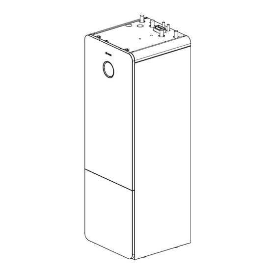
- Page 1 Installation Instructions Indoor unit for air to water heat pump Compress 3800i AW CS3800iAW AWM 13 0010038628-001...
-
Page 2: Table Of Contents
7.2.2 Cable feeds in the indoor unit ....18 7.2.3 Terminal connections in electric box....20 Compress 3800i AW – 6721889832 (2024/04) -
Page 3: Explanation Of Symbols And Safety Instructions
▶ The discharge pipe connected to the pressure relief device shall be These include, for example, product-specific information and service installed downwards and to a frost-free drain. instructions for maintenance and troubleshooting. Compress 3800i AW – 6721889832 (2024/04) -
Page 4: Product Information
There should be at least 50 mm between the indoor unit's sides and other fixed installations (walls, sinks, etc.). Ideal positioning is by an external wall or a partition wall. 0010038921-003 Fig. 2 Minimum distance (mm) Compress 3800i AW – 6721889832 (2024/04) - Page 5 Product Information _ > 50 0010038640-002 Fig. 3 Dimensions (mm) Compress 3800i AW – 6721889832 (2024/04)
- Page 6 Product Information 514,5 422,1 386,5 217,8 152,3 86,8 0010038642-002 Fig. 4 Dimensions, connections, top view Compress 3800i AW – 6721889832 (2024/04)
-
Page 7: Product Overview
Heat carrier pump PC0 date of manufacture of the device. Manometer Inspection hatch Anode Drain valve DHW cylinder Drain valve heating water (CH) [10] Manual purge valve [11] Expansion vessel [12] Heating system primary pump PC1 Compress 3800i AW – 6721889832 (2024/04) -
Page 8: Roof Panel
• Equipment for filling of heating and DHW system document. The address of our website is on the back of these • Non-return valve if the cooling mode is to be used. instructions. Compress 3800i AW – 6721889832 (2024/04) -
Page 9: Optional Accessories
Follow country-specific regulations, directives and standards for drinking water. The water quality in the cylinder has to comply with the framework of the EU directive 2020/ 2184. The following values must be emphasized: Compress 3800i AW – 6721889832 (2024/04) -
Page 10: Prepatory Work
11.Connect the EMS-BUS cable to accessories if needed. 12.Fill and vent the DHW cylinder. 13. Fill and vent the heating system before commissioning. 14.Establish the electrical connection of the system. 15.Commission the system. 16.Vent the heating system also during the commissioning. Compress 3800i AW – 6721889832 (2024/04) -
Page 11: Sizing The Dhw Circulation Lines
When exclusively fan convectors with a drain and insulated pipes are used, the flow temperature can be reduced to 7 °C. Maximum load at relay outputs: 5A, 400W, cos At a higher load an intermediate relay must be installed. Compress 3800i AW – 6721889832 (2024/04) -
Page 12: Hydraulic Connection
▶ Before connecting the heat pump and indoor unit, rinse the pipe system to remove any foreign bodies. If Installation is done without a heating circuit, the pipes needs to be capped. ▶ Put caps on the flow- and return pipes to the heating system. Compress 3800i AW – 6721889832 (2024/04) - Page 13 3) A flow rate of 15 l/min must be guaranteed on the primary side. Table 2 Pipe dimensions and maximum pipe lengths (one-way) for connecting a heat pump to indoor unit CS3800i AWM 13 Compress 3800i AW – 6721889832 (2024/04)
-
Page 14: Connect The Indoor Unit To The Heat Pump
Fig. 12 Connect the indoor unit to the heat pump Heat transfer medium in (from heat pump) Heat transfer medium out (to the heat pump) Filling equipment and fill valve VW2 Flow line from the heat pump Return line to the heat pump Compress 3800i AW – 6721889832 (2024/04) -
Page 15: Connect The Indoor Unit To The Heating System
▶ If necessary, connect an additional temperature switch at the voltage It is mandatory to install a non-return valve to use the cooling input of the respective circulation pump and to one of the external mode (see required accessories chapter in 3.8.1). inputs. Compress 3800i AW – 6721889832 (2024/04) -
Page 16: Connect The Indoor Unit To The Tap Water
At delivery the default position of the three-way valve VW1 is in middle position. 0010038743-002 Fig. 15 Heat pump connections tap water Domestic hot water out Cold water inlet Compress 3800i AW – 6721889832 (2024/04) - Page 17 13.Continue filling until only water comes out of the drain hose. 14.Open the valve VC3 to fill the buffer cylinder. 15.Continue filling until only water comes out of the drain hose and there are no more bubbles in the heating system. Compress 3800i AW – 6721889832 (2024/04)
-
Page 18: Electrical Connection
230V~1N, input to indoor unit (control unit) Table 3 Cable area and cable type 400V~3N, input to indoor unit (booster heater) Fixing points on sheet metal plate for fixing the cables with cable ties Electric box Compress 3800i AW – 6721889832 (2024/04) - Page 19 ▶ After inserting the cables, tighten the cable glands (Figure 19 [3], [4], [5]). ▶ Use the defined fixing points [9] to fix the cables that was inserted through the entries (Figure 19 [1], [2]). Compress 3800i AW – 6721889832 (2024/04)
-
Page 20: Terminal Connections In Electric Box
Electrical connection 7.2.3 Terminal connections in electric box Please note the jumper arrangement. 0010041530-004 Fig. 21 Electrical connections 400V ~3N input to indoor unit Compress 3800i AW – 6721889832 (2024/04) -
Page 21: Terminal Connections Of Accessories In Electric Box
Electrical connection 7.2.4 Terminal connections of accessories in electric box 0010041833-002 Fig. 22 Electrical connections for accessories 230V ~1N relay output to circulation pump PW2, DHW circulation 230V ~1N relay output PK2, cooling season Compress 3800i AW – 6721889832 (2024/04) -
Page 22: Connections Xcu-Thh (Xcu Hy) Module
CAN-BUS to heat pump The tightening torque of the screws for the connectors of the XCU-THH (XCU HY) must be 0.5Nm. ▶ Place a cable tie in front of each XCU-THH (XCU HY) connector. Compress 3800i AW – 6721889832 (2024/04) -
Page 23: Can-Bus
▶ Use cable with a conductor cross section of at least 0.5 mm ▶ In case of external inductive interferences (e.g. from PV systems), use screened cables. The screen should only be earthed to a chassis at one end. Compress 3800i AW – 6721889832 (2024/04) -
Page 24: External Inputs
Start menu or make additional settings in the service menu. Several functions are only displayed if they have been activated or if the relevant accessories have been installed. Compress 3800i AW – 6721889832 (2024/04) -
Page 25: Heat Pump, Indoor Unit And Heating System Ventilation
▶ If the pressure does not remain constant, check whether the heating 3) The maximum temperature setting is depending on the variant of the indoor unit. system and the expansion vessel are tight. Table 4 Configuration wizard Compress 3800i AW – 6721889832 (2024/04) -
Page 26: Function Test
▶ Check the operating pressure. ▶ Check the heating and DHW settings. ▶ Reset the overheating protection. To do this, press the button on the electrical heater. Compress 3800i AW – 6721889832 (2024/04) -
Page 27: Decommissioning
The heat pump insulation material will deform if it is exposed to high temperatures. ▶ Use a heat protection cover or wet rag as protection for the insulation material during soldering work on the heat pump. ▶ Use only original spare parts! Compress 3800i AW – 6721889832 (2024/04) -
Page 28: Checking The Magnesium Anode
( Fig. 30). The anode tester is available as an accessory. NOTICE Corrosion damage! If the anode is neglected, this could lead to premature corrosion. ▶ Inspect the anode every one or two years, depending on the on-site water quality, replace if required. Compress 3800i AW – 6721889832 (2024/04) -
Page 29: Service Of Expansion Vessel
10.Open valves to the heating system, SC1 and VC3, as well as valve VC4 between indoor unit and outdoor unit. 11.Vent the appliance and the heating system to remove any air from the system. Compress 3800i AW – 6721889832 (2024/04) -
Page 30: Environmental Protection And Disposal
Data Protection Officer, Information Security and Privacy (C/ISP), Environmental protection is a fundamental corporate strategy of the Robert Bosch GmbH, Postfach 30 02 20, 70442 Stuttgart, GERMANY. Bosch Group. The quality of our products, their economy and environmental safety are... - Page 32 Bosch Thermotechnik GmbH GB Importer: Junkersstrasse 20-24 Bosch Thermotechnology Ltd. 73249 Wernau, Germany Cotswold Way, Warndon www.bosch-homecomfortgroup.com Worcester WR4 9SW, United Kingdom...
Need help?
Do you have a question about the Compress 3800i AW and is the answer not in the manual?
Questions and answers