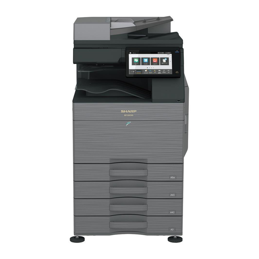
Sharp BP-50C26, BP-50C31, BP-50C36, BP-50C45 Manual
- Quick start manual (46 pages) ,
- Quick start manual (45 pages) ,
- Installation manual (34 pages)
Advertisement
CONFIGURATION
System diagram

Option list

STD: Standard equipment
OPT: Installable option
*1: Option in some area
*2: No support in some area
SIMULATION
General and purpose
The simulation mode has the following functions, to display the machine operating status, identify the trouble position and causes in an earlier stage and to efficiently setup and adjust the machine for improved serviceability.
- Various adjustments
- Setting of the specifications and functions
- Canceling troubles
- Operation check
- Counters check, setting clear
- Machine operating conditions (operation hysteresis) data check, clear
- Various (adjustments, setting, operation, counters, etc) data transport.
The operating procedures and displays depend on the design of the operation panel of the machine.
Simulation mode
| Easy mode | Displays commonly used simulations for each category, allowing easy access for technicians to change settings, perform maintenance and adjustments. |
| Classic mode | All simulations are listed and can be accessed by entering the main code, then sub code as per previous model series. |
Function of each key

| No. | Name | Function |
| 1 | TEST key | Change test mode |
| 2 | Mode setting key | Change Easy mode, Classic mode |
| 3 | Language setting key | Change language in simulation mode |
| 4 | INFO key | Display operation of current display |
| 5 | EXIT key | Exit from simulation mode |
| 6 | BACK key | Back to the previous display |
| 7 | Clear key | Clear input value |
Starting the simulation
Entering the simulation mode.
- Double tap the HOME ke
- Tap the Ver display section (10-key mode input mode screen)

- Touch the (#) key → Asterisk (*) key → Clear key → Asterisk (*) key → Ready for input of main code of simulation.


MAIN UNIT
Unpacking
- Cut the polypropylene bands.
![]()
- Remove the top case, cushioning materials, and case of the main unit.
![]()
- Remove F -add. Remove the vinyl bag of the main unit.
![]()
- Pull out the grips.

- Lift the main unit slowly by 4 people, and put it gently to the flat and safety place.


Fixing tape and protection material removal

- Open front cover and remove the silica gel.
![]()
- Push lock levers on both ends of waste toner box inward and pull up waste toner box.

- Remove tape from waste toner box.
* Tape is used when moving the machine, so keep it as needed.

- Make sure that the lock lever has moved to the position indicated by the arrow.

- Remove the protection material.
![]()
- Open the right door.
![]()
- Remove the fixing material (4 places) of the transfer unit and the label.


Packed items check

| No. | Name | Quantity |
| 1 | Operation manual | 1 |
| 2 | Protection sheet | 1 |
Lock release
- Tray rotation plate lock release
- Pull out the tray. Turn the fixing material and remove it. Remove the caution label.
Attach the removed fixing material to the position shown in the figure for future use.
Close the tray which was pulled out.

- Pull out the tray. Turn the fixing material and remove it. Remove the caution label.
- Scanner (2/3 mirror unit) lock release
- Remove the optical unit fixing screw, and remove the note label.
![]()
- Attach the protection sheet. (Packed item No.2)
![]()
- Remove the optical unit fixing screw, and remove the note label.


Installation

When an optional paper feed desk is connected to the machine, unpack and install the paper feed desk, then unpack the machine.
Place the machine on the option desk securely, and perform the installing procedures of the machine.
Place the machine on the optional desk firmly and secure.
This models have been shipped with developer enclosed into the developer unit and done SIM25-2. Therefore do NOT execute SIM25- 2 at machine installation.
If executed SIM25-2, replace all of the developers with new ones and execute SIM25-2. If the machine have been used without replacing the new developer. It may be trouble related to the life performance.
Toner cartridge installation
- Shake the toner cartridge horizontally several times
- Open the front cover and insert each toner cartridge
Be sure to install the color cartridge to their proper positions. Avoid installation to a different color position.
Do not forcibly insert the toner cartridge.
Push it in until the cartridge is securely locked in place.

Mounting location of the toner cartridge of each color
Cleaning of LSU's dust-proof glass
Dust from the transfer belt or shutter or some other adjacent part may fall onto the LSU during transport or installation. Be sure to clean the dust-proof glass before checking the image quality.
- Detach the LSU cleaning bar from the front cover.

- Turn the felt side of the cleaning bar downward and insert it. Slide it back and forth a few times to clean the LSU dust-proof glass.

- Return the LSU cleaning rod to the front cover so that the felt faces upward. Fit the boss, and fix it with three pawls.

- Attach the waste toner box.
Both ends being locked surely.

- Turn ON the main power switch then close the front cover.


For the destination EXIT TRAY CABINET option. Finisher or exit tray cabinet have to be installed before turning on the machine otherwise get L4-11 code will occur.
- Turn ON the operation panel power switch.
Do not operate the main unit for 20 seconds after turning on the power due to the contact operation check of the charging roller.
* In rare cases, JAM display may appear when operated.
* If JAM display appears, cancel JAM by opening and closing the right door and clear JAM history.
- Press OK.

- MFP Automatically rebooted and enters the toner replenishment operation
Confirm that "Toner replenishment in progress" is displayed and wait until the display disappears (it takes 30 sec - 4min)
Note
This procedure is for checking the toner supply operation from the toner cartridge to the DV unit. The operation time differs depending on the toner quantity in the toner cartridge. Uneven distribution of toner and the internal state of the toner cartridge.

Paper feed tray setup
- System setting
- Tap [SETTINGS] key.
- Tap [Init. Install Settings] key.
- Tap [Password] key at the Administrator Login. Enter the password with 10-key. "admin"
- Tap [Paper Tray Settings] key to configure the settings. These settings specify the paper type, paper size, and functions allowed for each paper tray. When the [Tray Settings] key is tapped, a list appears showing the trays and the current settings.
- Tap [Each tray] key in the above screen to change the settings.
The following settings can be configured.
| Item | Description |
| Type | Select the type of paper that is loaded in the tray. The paper types that can be selected vary by paper tray. |
| Size | Select the paper size from the list. The paper sizes that can be selected vary by tray. The sizes that can be selected may also be restricted by the paper type selected above. If the desired size does not appear in the list, select [Custom Size] and directly enter the size (only for the bypass tray). |
| Feeding Approved Job | Select the modes that can be used. If there is a function that you do not wish to be used with the selected tray, disable the function. When the "Type" is other than plain paper, recycled paper, colored paper, or a user type, [Fax] and [Internet Fax] cannot be selected. |
- Tray size setup
- Pull out the paper tray.
Gently pull the tray out until it stops.
If paper remains in the tray, remove it.

- Adjust the guide plates A and B by squeezing their lock levers and sliding them to match the vertical and horizontal dimensions of the paper to be loaded.
The guide plates A and B are slidable. Slide each guide plate while squeezing its lock lever.

- Adjust the guide plates A and B by squeezing their lock levers

- Pull out the paper tray.


Specifications setup
Use SIM26-6 to set the machines destination.
| SIM No | Content | |
| 26 | 6 | Used to set the destination. |
After completion of destination settings, change the set values to customize the following settings.
| SIM No | Content | |
| 26 | 3 | Used to set the auditor specification mode. |
| 5 | Used to set the count mode of the total counter and the maintenance counter. | |
| 18 | Used to set YES/NO of the toner save mode (Only in UK and Japan versions) * For other destination versions, this setup is made by the user program. | |
| 29 | Used to set remote firmware update mode. | |
| 52 | Used to set YES/NO of counting when non-print paper is passed through each counter. | |
Image quality check
Execution items
Execute the following items.
| No. | Item | SIM |
| 1 | Print engine image distortion adjustment (Manual adjustment) / OPC drum phase adjustment (Automatic adjustment) / Color registration adjustment (Automatic adjustment) | 50-22 |
| 2 | Copy color balance and density check | |
| 3 | Printer color balance/density check | 64-5 |
When there are defects in a picture by the contents mentioned above, you carry out the following contents, and confirm a picture.
| No. | Item | SIM |
| 4 | Copy/Printer color balance adjustment (Automatic adjustment) | 46-74 |
| 5 | Print/scan image off-center, lead edge position adjustment | 50-10 |
Description
- Print engine image distortion adjustment (Manual adjustment) / OPC drum phase adjustment (Automatic adjustment) / Color registration adjustment (Automatic adjustment)
This adjustment performs the print engine image distortion adjustment, the OPC drum phase adjustment, and the color registration adjustment simultaneously.
- Enter SIM50-22 mode.
- Press [EXECUTE] key.
[EXECUTE] key is highlighted and the image registration automatic adjustment is started. (It takes about 30 sec to complete the adjustment.) - When the adjustment is completed, [EXECUTE] key returns to the normal display, and the value of the adjustment result is displayed.
The current skew level for each color is displayed on the SKEW display section.

- Write down the displayed skew level.
(Meaning of the skew level value and the adjustment procedure)
* If "OK" is displayed for all items of SKEW C, M, and Y, there is no need to perform the adjustment.
* When "R" is displayed at the head of the value, turn the LSU skew adjustment screw clockwise.
* When "L" is displayed at the head of the value, turn the LSU skew adjustment screw counterclockwise.
* The turning amount of the adjustment screw corresponds to each adjustment value. C, M, and Y indicate numbers of clicks. The display value is rounded at the decimal point.
* "C, M, and Y(SKEW)" shows the number of adjustment click steps for each adjustment screw of C, M, and Y.
Contents in ( )
MIAN, SUB: Difference from the previous adjustment value of image registration.
Example:
If 105 for this time and 103 for the previous time, it is displayed as 105.0 (+2.0).
SKEW: Judgment of the LSU skew adjustment result. OK or NG.
PHASE: OPC drum phase adjustment value of the previous time - The procedures 2) to 4) again, and check to confirm that C, M, and Y (SKEW) are OK.
If any of them is NG, turn the LSU skew adjustment screw of the corresponding color to adjust.


When the adjustment is made by turning the LSU skew adjustment screw of K, the states of C, M and Y (SKEW) are changed. Execute SIM50-22 to check to confirm that C, M, and Y (SKEW) are OK.
When an abnormality occurs, "ERROR" is displayed.
In this case, check each drive section and the process section.
- Copy color balance and density check
Method
Make a copy of the gray test chart (UKOG-0162FCZZ) and a copy of the servicing color test chart (UKOG-0326FCZZ/UKOG-0326FC11), and check that they are proper.- Note for execution of the color balance and density check in the color copy mode To check the copy color balance and density, use the gray test chart (UKOG-0162FCZZ) and the servicing color test chart (UKOG- 0326FCZZ/UKOG-0326FC11). Set the copy density level to "3" in the Text/Printed Photo mode (Manual), and make a copy.
At that time, all the color balance adjustments in the user adjustment mode must be set to the default (center). In addition, be sure to use the specified paper for color. - Note for checking the monochrome copy mode density
To check the density, use the gray test chart (UKOG-0162FCZZ). Set the copy density level to "Manual 3" in the Text/Printed Photo mode (Manual).
In addition, all the color balance adjustments in the user adjustment mode must be set to the default (center).
- Note for execution of the color balance and density check in the color copy mode To check the copy color balance and density, use the gray test chart (UKOG-0162FCZZ) and the servicing color test chart (UKOG- 0326FCZZ/UKOG-0326FC11). Set the copy density level to "3" in the Text/Printed Photo mode (Manual), and make a copy.

[Check with the gray test chart (UKOG-0162FCZZ)]
In the copy density check with the gray test chart, check to insure the following conditions.
For the color (gray) balance, use the servicing color test chart (UKOG- 0326FCZZ/UKOG-0326FC11) to check.

[Check with the servicing color test chart (UKOG-0326FCZZ/UKOG- 0326FC11)]
In the copy color balance check with the servicing color test chart, check to insure the following conditions.
- Color copy check items (Check to confirm the following:)

- There are 12 void areas.
- Registrations (one point for the main scanning, and one point for the sub scanning) are not shifted.
- The resolution of 5.0 (5 points) can be seen.
- The color difference in gray balance between the F and the R sides is not so great.
- There are no white and black streaks.
- Color texts are clearly reproduced.
- Solid density is not so light.
- Monochrome copy check items (Check to confirm the following:)

- There are 12 void areas.
- The resolution of 4.0 (5 points) can be seen.
- The density difference between the F and the R sides is not so great.
- There are no white and black streaks.
- Solid density is not so light.
- The black low-density gradation is copied slightly.


- Printer color balance/density check
Method
Execute SIM64-5 to print the print test pattern.


Set each set value to the default and press [EXECUTE] key. The print test pattern is printed.
The print density must be changed gradually from the lighter level to the darker level. The density changing direction must not be reversed. The density level of each color must be almost at the same level.
- Copy/Printer color balance and density adjustment (Automatic adjustment)
When a printer option is installed, be sure to execute the above item.
- Enter the SIM46-74 mode.
- Press [EXECUTE] key.
The high density process control is performed, and the copy color patch image (adjustment pattern) is printed out. (A4/11" x 8.5" or A3/11" x 17" paper is automatically selected.) - Set the color patch image (adjustment pattern) paper printed in procedure 2) on the document table.
Set the color patch image (adjustment pattern) printed in the procedure 2) on the document table. Place the color patch image so that the fine lines are on the left side. At that time, place 5 sheets of white paper on the printed color patch image (adjustment pattern).
![]()
- Select [FACTORY] target, and press [EXECUTE] key.
When the color balance is customized by the manual color balance adjustment (SIM46-21) according to the user's request, and the color balance is registered with SIM63-7 as the service target, if the color balance is required to be adjusted, select the [SER- VICE] target.
The copy color balance adjustment is automatically executed and prints the color balance check patch image.
If there is any streak or unclear print on the printed check pattern, check the print engine for any problems.
![]()
- Press [EXECUTE] key.
The printer color patch image (adjustment pattern) is printed out. (A4/11" x 8.5" or A3/11" x 17" paper is automatically selected.) - Set the color patch image (adjustment pattern) printed in the procedure 5) on the document table.
Set the color patch image (adjustment pattern) printed in the procedure 2) on the document table. Place the color patch image so that the fine lines are on the left side. At that time, place 5 sheets of white paper on the printed color patch image (adjustment pattern).
![]()
- Select [FACTORY] target, and press [EXECUTE] key.
When the color balance is customized with the manual color balance adjustment (SIM67-25) according to the user's request and the color balance is registered as the service target with SIM67- 27, if the color balance is adjusted to that color balance, select the [SERVICE] target.
The printer color balance adjustment (step 1) is automatically performed and the color balance check patch image is printed out.
If there is any streak or unclear print on the printed check pattern, check the print engine for any problems.
![]()
- The initial setting menu of the half-tone image correction is displayed. Press [OK] key.
The initial setting of the half-tone image correction is performed. - Wait until [EXECUTE] key is displayed. When it is displayed, press it.
The half-tone image correction is performed. - When "COMPLETED THIS PROCEDURE" is displayed, the adjustment operation is completed.
Cancel SIM46-74.


The adjustment result becomes valid only when the both adjustments in the copy mode and in the printer mode are completed.
For example, if the copy color balance adjustment (automatic adjustment) is performed and the simulation is canceled, the adjustment result is invalid.
- Check the copy color balance and density. (Refer to the item of the copy color balance and density check.)
- Check the printer color balance and density. (Refer to the item of the printer color balance and density check.)
If the color balance or density is not in the satisfactory level even after execution of the automatic and manual adjustments, there may be another cause.
Troubleshoot the cause, repair or perform necessary works, and repeat the adjustment from the beginning.
If color balance or density is not satisfied, adjust the copy and printer color balance by SIM46-74.
- Print/scan image off-center, lead edge position adjustment.
Before executing this adjustment, be sure to check the following items.
* There must be a tray with A4 (LT) paper in it.- Enter the SIM50-10 mode.
- Select a paper feed tray 1.
- Set A4 (11 X 8.5) paper on the paper feed tray 1.
- Check to confirm that the inside dimension of the printed half-tone pattern is 240 1.2mm.
- Measure the void area size of the adjustment pattern in the front/ rear frame direction (F side void amount) and that in the transport direction (Lead edge void amount).
Check to confirm that all the following conditions are satisfied.


Calculation and input procedures of adjustment values
(Example) Lead edge void amount
- Measure by visual inspection.
→ Measurement result: 4.5mm - Calculate the shift amount.
The target value is the specification value (center value) of 3mm.
* For the F side void amount, the target is 2mm.
→ [4 – 4.5 = -0.5 (mm)] - Calculate the adjustment value. Subtract 5 from the shift amount of -0.5mm.
* For the shift amount of 0.1mm, the adjustment value is varied by 1.
When the current value is 50:
→ [50 – 5 = 45] - Enter the adjustment value for SUB-CS1.
→ Enter the [45].
- Enter MAIN-CS1 (F side void) and SUB-CS1 (Lead edge void), and press OK button.
Enter the calculated adjustment values for the shift amount to MAIN-CS1/SUB-CS1, and press OK button. (The cursor can be used instead of the button.) - After entering the adjustment values, print again and check to confirm that the avoid amounts are adjusted to the target range.
BP-DE12/DE13/DE14 SHEET PAPER DRAWER
(STAND/550/2x550/3x550 SHEET PAPER DRAWER)
Unpacking
Before installation, be sure to turn both the operation and main power switches off and disconnect the power plug from the power outlet. Make double sure that the data lamp on the operation panel does not light up or blink when performing installation.

Packed items check
| No. | Name | Quantity |
| 1 | Desk unit | 1 |
| 2 | Fixing screws (M4 x 8) | 4 |
| 3 | Right adjuster | 1 |
Installation
Adjuster position adjustment
- Attach right adjuster (Packed item No.3)


Note
If following option is not installed at the same time, the adjuster must be installed.
- LARGE CAPACITY TRAY
- FINISHER (1k)
- SADDLE STITCH FINISHER (1K)
- FINISHER (3K)
- SADDLE STITCH FINISHER (3K)
To ensure safety, insert right adjuster until it is locked.
- Turn each adjuster to fix the desk unit.
![]()

Main unit and desk unit connection
- Put the main unit on the desk unit.
Use man power of four persons or more to lift the main unit.

Place the main unit on the desk unit slowly by fitting the external lines. Check to insure that the positioning pin on the top of the desk unit is securely engaged in the positioning groove of the main unit.

- Remove the tray 1 and the tray 2.

- Raise the linkage plates on the right and left sides of the front side of the desk unit, and fix them with the fixing screws (Packed item No.2).

- Attach the tray 1 and the tray 2.
![]()
- Remove cover of the main body rear. And fix them with the fixing screws (Packed item No.2). Return small covers.


Release the lock
- Pull out each tray. Turn and remove the fixing material, and remove the caution sheet.
Attach the removed fixing material to the position shown in the figure for storage.
Close the cassette which was pulled out.


Before turning on the power, check to insure that the fixing material of the tray is disengaged. If the power is turned on without disengaging the fixing material, a trouble may be resulted.
Connector connection
- Remove the cover from the rear side of the machine.

- Connect the connector.
![]()
- Separate the base of the cover in nippers.

- Attach the cover.


Adjustment
Before installation, be sure to turn both the operation and main power switches off and disconnect the power plug from the power outlet. Make double sure that the data lamp on the operation panel does not light up or blink when performing installation.
Turn ON the power of the main unit
- Connect the power plug of the machine to the power outlet, and turn ON the main power switch and the operation panel power switch.
Note
For setting the tray size, refer to "Tray size setup".
Image off-center adjustment
Note
The image lead edge position and the off-center adjustment value of the desk unit have been set to the average value when shipping from the factory.
Therefore, this adjustment must be performed only when the judgment is made to execute it through checking the print image.
* There must be a tray with A4 (LT) paper in it.
- Enter the SIM50-10 mode.
- Select a paper feed source "3" (CS2).
- Set A4 (11 X 8.5) paper on the CS2 paper feed tray.
- Check to confirm that the inside dimension of the printed half-tone pattern is 240 1.2mm.
If the above condition is not satisfied, follow and repeat the procedures of ADJ4A(Service manual) until a satisfactory result is obtained. - Measure the void area size of the adjustment pattern in the front/ rear frame direction (F side void amount) and that in the transport direction (Lead edge void amount).
Check to confirm that all the following conditions are satisfied.


Calculation and input procedures of adjustment values
(Example) Lead edge void amount
- Measure by visual inspection. Measurement result: 4.5mm
- Calculate the shift amount.
The target value is the specification value (center value) of 3mm.
* For the F side void amount, the target is 2mm.
→ [4 – 4.5 = -0.5 (mm)] - Calculate the adjustment value. Subtract 5 from the shift amount of -0.5mm.
* For the shift amount of 0.1mm, the adjustment value is varied by 1.
→ When the current value is 50: [50 – 5 = 45] - Enter the adjustment value for SUB-CS2/CS3/CS4. Enter the [45].
- Enter MAIN-CS2 (F side void) and SUB-CS2 (Lead edge void), and press OK button. Enter the calculated adjustment values for the shift amount to MAIN-CS2/SUB-CS2, and press OK button. (The cursor can be used instead of the button.)
- After entering the adjustment values, print again and check to confirm that the avoid amounts are adjusted to the target range.
Perform procedures 4) to 7) for each paper feed tray.
BP-DE15 SHEET PAPER DRAWER
(STAND/550&2100 SHEET PAPER DRAWER)
Unpacking
If the connector is removed first, it may be damaged during the installation procedures. Therefore, keep it packed while un-boxing. and unpack it only when connecting the connector to the machine.

Packed items check
| No. | Name | Quantity |
| 1 | Desk unit | 1 |
| 2 | Fixing screws (M4 x 8) | 4 |
| 3 | Right adjuster | 1 |
Installation
Before installation, be sure to turn both the operation and main power switches off and disconnect the power plug from the power outlet. Make double sure that the data lamp on the operation panel does not light up or blink when performing installation.
Adjuster position adjustment
- Attach right adjuster (Packed item No.3)


Note
If following option is not installed at the same time, the adjuster must be installed.
- LARGE CAPACITY TRAY
- FINISHER (1k)
- SADDLE STITCH FINISHER (1K)
- FINISHER (3K)
- SADDLE STITCH FINISHER (3K)
To ensure safety, insert right adjuster until it is locked.
- Turn each adjuster to fix the desk unit.
Main unit and desk unit connection
- Put the main unit on the desk unit.
Use man power of four persons or more to lift the main unit.

Place the main unit on the desk unit slowly by fitting the external lines. Check to insure that the positioning pin on the top of the desk unit is securely engaged in the positioning groove of the main unit.

- Remove the tray 1 and the tray 2.

- Raise the linkage plates on the right and left sides of the front side of the desk unit, and fix them with the fixing screws (Packed item No.2).

- Attach the tray 1 and the tray 2.
![]()
- Take off the small cover of right and left sides of the main body rear. And fix them with the fixing screws (Packed item No.2). Return small covers.


Release the lock
- Pull out the tray. Turn and remove the fixing material, and remove the caution sheet.
Attach the removed fixing material to the position shown in the figure for storage.
![]()
- Pull out each tandem tray. Turn and remove the fixing material, and remove the caution sheet.
Attach the removed fixing material to the position shown in the figure for storage.
Close the tray which was pulled out.
![]()


Before turning on the power, check to insure that the fixing material of the tray is disengaged. If the power is turned on without disengaging the fixing material, a trouble may be resulted.
Connector connection
- Remove the cover from the rear side of the machine.

- Connect the connector.
![]()
- Separate the base of the cover in nippers.

- Attach the cover.


Turn ON the power of the main unit
- Connect the power plug of the machine to the power outlet, and turn ON the main power switch and the operation panel power switch.
Tray setup
- System Settings
- Tap [Initial Installation Settings] key on the touch panel.
- Tap [Tray Settings] for respective setting. Set up paper type, paper size and Feeding Approved Job for each tray. Touch [Tray Settings] key to display the list of tray and current settings.
- Tap the respective tray key to display setting screen. The setting items are as listed below:
| Setting Items | Description |
| Type | Select the type of paper to be used. The type of selectable paper type varies depending on the tray. |
| Size | Select the size of paper to be used. The selectable size varies depending on the tray. The selectable size may be limited depending on the tray selected in the Type above. If the appropriate tray is not listed, select [Size Input] and designate the size directly. (This is allowed for Bypass Tray only.) |
| Feeding Approved Job | Select the approved job mode. Disable the feature do not wish to perform a job using the selected tray. [Fax] and [Internet Fax] cannot be selected if [Type] is set to anything other than Plain Paper, Recycle Paper, Color paper, or User Type. |
- Tray size setting
- Tray 2
- Pull out the paper tray.
Pull out the tray gently until it stops.
Remove the paper loaded into the tray. - Adjust guide plates A and B by squeezing their lock levers and sliding them to match the longitudinal and transversal dimensions of the paper to be loaded.
The guide plates A and B are slidable. Slide each guide plate while squeezing its lock lever to adjust to the paper size.

- Pull out the paper tray.
- Tray 3 (A4/LT)
- Pull out the Tandem paper feed tray.
- Remove the Tandem tray regulation plate while pressing a hook.

- Insert Adjust plate boss to the holes on the Tandem tray regulation plate for appropriate size.

- Push the Tandem paper feed tray.
- Tray 4 (A4/LT/B5)
- Pull out the Tandem paper feed tray.
- Remove the Tandem tray regulation plate while pressing a hook.

- Insert Adjust plate boss to the holes on the Tandem tray regulation plate for appropriate size.

- Lay B5 rear edge regulation plate to set for A4/LT size. Erect the regulation plate to set for B5 size.

- Push the Tandem paper feed tray.
- Tray 2
- Size setting
Execute SIM26-2 "Size setting" with the key operations of the main unit.- The size selection menu of the large capacity desk is displayed on the operation message display.
- Select a size button to be set on the message screen.


Image off-center adjustment
Note
The image lead edge position and the off-center adjustment value of the desk unit have been set to the average value when shipping from the factory.
Therefore, this adjustment must be performed only when the judgment is made to execute it through checking the print image.
* There must be a tray with A4 (LT) paper in it.
- Execute SIM50-10.
- Select a paper feed source "3" (CS2).
- Set A4 (11 X 8.5) paper on the CS2 paper feed tray.
- Check to confirm that the inside dimension of the printed half-tone pattern is 240 1.2mm.
If the above condition is not satisfied, follow and repeat the procedures of ADJ4A(Service manual) until a satisfactory result is obtained. - Measure the void area size of the adjustment pattern in the front/ rear frame direction (F side void amount) and that in the transport direction (Lead edge void amount).
Check to confirm that all the following conditions are satisfied.


Calculation and input procedures of adjustment values
(Example) Lead edge void amount
- Measure by visual inspection. Measurement result: 4.5mm
- Calculate the shift amount.
The target value is the specification value (center value) of 3mm.
* For the F side void amount, the target is 2mm.
→ [4 – 4.5 = -0.5 (mm)] - Calculate the adjustment value. Subtract 5 from the shift amount of -0.5mm.
* For the shift amount of 0.1mm, the adjustment value is varied by 1.
→ When the current value is 50:
[50 – 5 = 45] - Enter the adjustment value for SUB-CS2.
→ Enter the [45].
- Enter MAIN-CS2 (F side void) and SUB-CS2 (Lead edge void), and tap OK button.
Enter the calculated adjustment values for the shift amount to MAIN-CS2/SUB-CS2, and tap OK button. (The cursor can be used instead of the button.) - After entering the adjustment values, print again and check to confirm that the avoid amounts are adjusted to the target range.
Perform procedures 4) to 7) for each paper feed tray.
BP-LC10 LARGE CAPACITY TRAY
Unpacking
If the connector is removed first, it may be damaged during the installation procedures. Therefore, keep it packed while un-boxing and unpack it only when connecting the connector to the machine.

Packed items check
| No. | Name | Quantity |
| 1 | Large capacity tray | 1 |
| 2 | Mounting plate upper | 2 |
| 3 | Connecting unit | 1 |
| 4 | Fixing screw A (Hex washer S-tight M4x18) | 4 |
| 5 | Fixing screw B (Hex washer S-tight M4x12) | 2 |
| 6 | Fixing screw C (M4x8 cup) | 1 |
| 7 | LCC Guide sheet | 1 |
Installation
Before installation, be sure to turn both the operation and main power switches off and disconnect the power plug from the power outlet. Make double sure that the data lamp on the operation panel does not light up or blink when performing installation.
Release the lock
- Remove the paper feed desk fixing screw.


NOTE: Before turning on the power, check to insure that the fixing screw of the tray is removed. If the power is turned on without removing the fixing screw, a trouble may be resulted.
Main unit and large capacity tray connection
- Attach the mounting plate upper (Packed item No.2) to the right side of main unit with the fixing screw A (Packed item No.4). When installing, put the rubber section (
![]() ) of the mounting plate upper on the lower side.
) of the mounting plate upper on the lower side.
Note
If right adjuster is installed, remove it.
![]()
- Remove the right door cover from the machine.
![]()
- Attach the LCC guide sheet (Packed item No.7) onto the paper entering guide.
Clean surface of the LCC guide sheet with alcohol.


- Remove the fixing screws (1 pc) of the machine and remove the screw cap. And remove the right under cover.

- Temporarily fix the fixing screw B (Packed item No.5) midway.

- Insert the temporarily fixed screw B into the key hole in the connection unit and temporarily fix the connection unit.

- Fix the other fixing screw B and tighten the temporarily fixed screw B securely.

- Attach the right under cover back to the main unit.

- Fix the fixing screw, and attach the screw cap back to the main unit.

- While lifting the section marked with
![]() insert the connection unit into the large capacity tray and fix the fixing screw C (Packed item No.6) at the mark A on the connection unit.
insert the connection unit into the large capacity tray and fix the fixing screw C (Packed item No.6) at the mark A on the connection unit.

 ) of the mounting plate upper on the lower side.


 insert the connection unit into the large capacity tray and fix the fixing screw C (Packed item No.6) at the mark A on the connection unit.
Height adjustment
- Put the large capacity tray closer to the main unit.
![]()
- Check to insure that the height adjustment check rib of the large capacity tray and the axis line of the mounting plate upper mounted to the main unit are in the same line.
![]()
- If the height adjustment is not required, insert the large capacity tray further more.
If the height adjustment is required, perform the adjustment procedure from 4).

- Loosen the adjustment screw on the F side.
NOTE: Use the adjustment screw on the front side for the adjustment. Do not touch the screw on the rear side.
NOTE: If the screw is loosened or removed when servicing, be sure to execute C Height adjustment after completion of servicing.
![]()
- In the case of a shift to the right, press the front upper section and fit the height adjustment check rib so that it is in the same line with the axis line of the mounting plate upper. Insert the large capacity tray into the main unit.
![]()
- In the case of a shift to the left, lift the grid so that the height adjustment check rib is in the same line with the axis line of the mounting plate upper and insert the large capacity tray.
![]()
- Tighten the loosened screw.


Connector connection
- Remove the connector cover.
Do not use the connector cover removed.
![]()
- Connect the connector.
If the heater kit is not installed, there is no need to connect the heater connector to the connector.


Paper size switch
- Remove Rear cover.
![]()
- Remove fixing screw (4 pcs of blue screw) on upper and lower side of Side plate F and Side plate R.
![]()
- Insert the lower side according to the engraved mark on the lower side of Side plate F and Side plate R. Tighten upper and lower side using the fixing screws being removed.

![]()
- Switching Rear edge plate
Remove the blue screws fixing the upper and lower Rear edge plate respectively.

- Insert Size guide according to the engraved mark. Tighten upper and lower side using the fixing screws being removed (A4).

- Attach Rear cover.
![]()


Turn ON the power of the main unit
- Connect the power plug of the machine to the power outlet, and turn ON the main power switch and the operation panel power switch.
Size setting
Execute SIM26-2 "Size setting" with the key operations of the main unit.
- The size selection menu of the large capacity tray is displayed on the operation message display.
- Select a size button to be set on the message screen.
Image off-center adjustment
- Adjustment with the simulation
Note
The image lead edge position and the off-center adjustment value of the large capacity tray have been set to the average value when shipping from the factory.
Therefore, this adjustment must be performed only when the judgment is made to execute it through checking the print image.
* There must be a tray with A4 (LT) paper in it.- Execute SIM50-10.
- Select a paper feed source "6" (LCC).
- Set A4 (11 X 8.5) paper on the LCC paper feed tray.
- Check to confirm that the inside dimension of the printed half-tone pattern is 240 1.2mm.
If the above condition is not satisfied, follow and repeat the procedures of ADJ4A(Service manual) until a satisfactory result is obtained. - Measure the void area size of the adjustment pattern in the front/ rear frame direction (F side void amount) and that in the transport direction (Lead edge void amount).
Check to confirm that all the following conditions are satisfied.


Calculation and input procedures of adjustment values
(Example) Lead edge void amount
- Measure by visual inspection.
→ Measurement result: 4.5mm - Calculate the shift amount. The target value is the specification value (center value) of 3mm.
* For the F side void amount, the target is 2mm.
→ [4 – 4.5 = -0.5 (mm)] - Calculate the adjustment value. Subtract 5 from the shift amount of -0.5mm.
* For the shift amount of 0.1mm, the adjustment value is varied by 1.
→ When the current value is 50:
[50 – 5 = 45] - Enter the adjustment value for SUB-LC.
→ Enter the [45].
- Enter MAIN-LC (F side void) and SUB-LC (Lead edge void), and tap OK button.
Enter the calculated adjustment values for the shift amount to MAIN-LC/SUB-LC, and tap OK button. (The cursor can be used instead of the button.) - After entering the adjustment values, print again and check to confirm that the avoid amounts are adjusted to the target range.
Perform procedures 4) to 7) for each paper feed tray.
- Mechanical adjustment
Since the off-center adjustment is performed when shipping, there is basically no need to perform this adjustment. If the center is shifted, however, the simulation is normally used. If the shift is not removed, perform the following adjustment procedures.- When the shift is in the front side
To adjust the print line in the direction A from the paper center as shown in the figure:- Loosen two fixing screws (red screws) of the front/rear size guide adjustment plate, and move the size guide adjustment plate in the direction A (R side) by the shift amount, and tighten the red fixing screws (2 for each).
Then make a copy to check to insure that there is no more shift. Repeat the procedures until there is no shift.

- Loosen two fixing screws (red screws) of the front/rear size guide adjustment plate, and move the size guide adjustment plate in the direction A (R side) by the shift amount, and tighten the red fixing screws (2 for each).
- When the shift is in the rear side
To adjust the print line in the direction B from the paper center as shown in the figure:- Loosen two fixing screws (red screws) of the front/rear size guide adjustment plate, and move the size guide adjustment plate in the direction B (F side) by the shift amount, and tighten the red fixing screws (2 for each).
Then make a copy to check to insure that there is no more shift. Repeat the procedures until there is no shift.

- Loosen two fixing screws (red screws) of the front/rear size guide adjustment plate, and move the size guide adjustment plate in the direction B (F side) by the shift amount, and tighten the red fixing screws (2 for each).
- When the shift is in the front side


MX-LT10 LONG PAPER FEEDING TRAY
Unpacking

Packed items check
| No. | Name | Quantity |
| 1 | Long paper feeding tray | 1 |
Installation
Do not insert the finger in the hook part of the tray.

Long paper feeding tray attachment
- Open the long paper feeding tray guide and hook it to the lock of the long paper feeding tray.
![]()
- Pull out the guide of the machine.
![]()
- Hook the Long paper feeding tray to the guide of the machine.
![]()
- Insert the guide of the machine.
![]()


This tray can only be used for long paper feeding.
Do not leave long paper for an extended period of time.

You can use long paper with this tray.

Turn ON the power of the main unit
- Connect the power plug of the machine to the power outlet and turn ON the main power switch and operation panel power switch.
Tray setting
Use SIM26-50 to set "Banner size print" to 1.
Documents / ResourcesDownload manual
Here you can download full pdf version of manual, it may contain additional safety instructions, warranty information, FCC rules, etc.
Download Sharp BP-50C26, BP-50C31, BP-50C36, BP-50C45 Manual
Advertisement


Need help?
Do you have a question about the BP-50C26 and is the answer not in the manual?
Questions and answers