Table of Contents
Advertisement
Quick Links
Advertisement
Table of Contents

Related Manuals for Shinko AER-102-PH


Summary of Contents for Shinko AER-102-PH
- Page 1 Digital Indicating pH Meter AER-102-PH Instruction Manual...
- Page 2 • Any unauthorized transfer or copying of this document, in part or in whole, is prohibited. • Shinko Technos Co., Ltd. is not liable for any damage or secondary damage(s) incurred as a result of using this product, including any indirect damage.
-
Page 3: Safety Precautions
• This instrument must be used under the conditions and environment described in this manual. Shinko Technos Co., Ltd. does not accept liability for any injury, loss of life or damage occurring due to the instrument being used under conditions not otherwise stated in this manual. -
Page 4: Installation Precautions
• No water, oil or chemicals or where the vapors of these substances can come into direct contact with the unit • If the AER-102-PH is mounted through the face of a control panel, the ambient temperature of the unit - not the ambient temperature of the control panel - must be kept to under 50 . - Page 5 Note about the pH Combination Electrode Sensor Cable The pH combination electrode sensor cable is a highly-insulated (electrical) cable. Please handle it with utmost care as follows. • Do not allow terminals and socket of the pH combination electrode sensor cable to come in contact with moisture or oil of any kind.
-
Page 6: Table Of Contents
5.2 Setting Groups --------------------------------------------------------------------- 16 6. Key Operation Flowchart ----------------------------------------------------------- 18 7. Setup 7.1 Turn the Power Supply to the AER-102-PH ON --------------------------- 21 7.2 pH Input Group -------------------------------------------------------------------- 22 7.3 Temperature Input Group ------------------------------------------------------- 24 7.4 EVT1 Action Group --------------------------------------------------------------- 25 7.5 EVT2 Action Group --------------------------------------------------------------- 29... - Page 7 10. Specifications 10.1 Standard specifications -------------------------------------------------------- 53 10.2 Optional specifications --------------------------------------------------------- 59 11. Troubleshooting 11.1 Indication -------------------------------------------------------------------------- 60 11.2 Key Operation ------------------------------------------------------------------- 61 12 Character Tables 12.1 Setting Group List -------------------------------------------------------------- 62 12.2 Temperature Calibration Mode ---------------------------------------------- 62 12.3 pH Calibration Mode (for Manual pH calibration) -----------------------6262 12.4 Simple setting mode ----------------------------------------------------------- 63 12.5 pH Input Group ------------------------------------------------------------------ 64 12.6 Temperature Input Group ----------------------------------------------------- 64...
-
Page 8: Model Page
1. Model 1.1 Model A E R - 1 0 Input Points 2 points pH combination electrode sensor Input (Cu500/25 or Pt100) 100 to 240V AC (standard) Supply Voltage 24V AC/DC (*) Serial communication RS-485 Option EVT3 EVT3, EVT4 Output (contact output 3, 4) (*) Supply voltage 100 to 240V AC is standard. -
Page 9: Name And Functions Of Sections
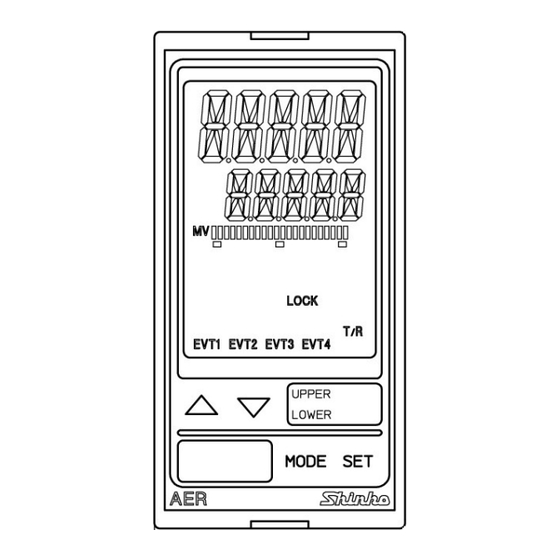
2. Name and Functions of Sections pH Display Temperature Display Output Display Action Indicators Increase Key MODE Key Decrease Key SET Key (Fig. 2-1) Displays pH Display: pH or setting characters in the setting mode are indicated with the red/green/orange LED. Indications differ depending on the selections during [Backlight Selection (p.43)] and [pH color (p.43)]. -
Page 10: Mounting To The Control Panel
Temperature: 0 to 50 (32 to 122 ) (No icing), Humidity: 35 to 85%RH (Non-condensing) If AER-102-PH is mounted through the face of a control panel, the ambient temperature of the unit - not the ambient temperature of the control panel - must be kept to under 50 , otherwise the life of electronic parts (especially electrolytic capacitors) of the unit will be shortened. -
Page 11: Panel Cutout (Scale: Mm)
3.3 Panel Cutout (Scale: mm) Caution If lateral close mounting is used for the unit, IP66 specification (Drip-proof/Dust-proof) may be compromised, and all warranties will be invalidated. +0.5 n×48-3 Lateral close mounting n: Number of units mounted +0.5 (Fig. 3.3-1) - 11 -... -
Page 12: Mounting And Removal
3.4 Mounting and Removal Caution As the case is made of resin, do not use excessive force while screwing in the mounting bracket, or the case or mounting brackets could be damaged. The torque should be 0.12N•m. How to mount the unit Mount the unit vertically to the flat, rigid panel to ensure it adheres to the Drip-proof/Dust-proof specification (IP66). -
Page 13: Wiring
• Use a solderless terminal with an insulation sleeve in which the M3 screw fits when wiring the AER-102-PH. • Tighten the terminal screw using the specified torque. If excessive force is applied to the screw when tightening, the terminal screw may be damaged. -
Page 14: Lead Wire Solderless Terminal
Note about the pH Combination Electrode Sensor Cable The pH combination electrode sensor cable is a highly-insulated (electrical) cable. Please handle it with utmost care as follows. • Do not allow terminals and socket of the pH combination electrode sensor cable to come in contact with moisture or oil of any kind. -
Page 15: Terminal Arrangement
4.2 Terminal Arrangement (Fig. 4.2-1) Ground POWER SUPPLY 100 to 240V AC or 24V AC/DC (when 1 is added after the model) For 24V DC, ensure polarity is correct. EVT1 EVT1 output (contact output 1) EVT2 EVT2 output (contact output 2) TRANSMIT OUTPUT Transmission output G, R Electrode sensor... -
Page 16: Outline Of Key Operation And Settinggroups
5. Outline of Key Operation and SettingGroups 5.1 Outline of Key Operation There are 2 setting modes: Simple Setting mode, and Group Selection mode in which setting items are divided into groups. To enter the Simple setting mode, press the key in the pH/Temperature display mode. - Page 17 [pH/Temperature Display mode, Temperature Calibration mode] (*1) In the pH/Temperature Display mode, indicates the item selected during [Backlight selection (p.43)] in the Special function group, and measurement starts. (*2) If (No temperature compensation) is selected during [Electrode RTD (p.24)] in the Temperature input group, the unit does not move to the Temperature calibration mode.
-
Page 18: Key Operation Flowchart
Key Operation Flowchart Power ON (3sec) pH/Temperature Display Mode Temp. Calibra- (*1) tion Mode (*2) (3sec) pH/ Temperature pH Calibration Display Mode Mode EVT1 Value pH Input Temperature Group Input Group EVT2 Value pH7 calibration Electrode RTD standard (*2) EVT3 Value 2nd solution Reference temperature... - Page 19 [pH/Temperature display mode, Temperature calibration mode] Indicates the item selected during [Backlight selection (p.43)] in the Special function group, (*1) then measurement starts. (No temperature compensation) is selected during [Electrode RTD (p.24)] in the (*2) If Temperature input group, the unit does not move to the Temperature calibration mode. [Setting groups and items with dotted lines] Setting groups and items with dotted lines are indicated only when the options are added.
- Page 20 [About Setting Items] • Upper left: pH Display: Indicates the setting item characters. EVT1 value • Lower left: Temperature Display: Indicates factory default value. • Right side: Indicates the setting item. [About Key Operation] is pressed for 3 sec while is pressed, the unit will enter the next setting item.
-
Page 21: Setup
EVT3, EVT4 Action Groups and Special Function Group. If the users’ specification is the same as the default value of the AER-102-PH, or if setup has already been complete, it is not necessary to set up the instrument. Proceed to Chapter “8. -
Page 22: Ph Input Group
7.2 pH Input Group To enter the pH input group, follow the procedures below. Press the key once in the pH/Temperature display mode. Press the key once. The unit proceeds to the pH input group, and “pH 7 calibration standard” item is indicated. - Page 23 Name, Function, Setting Range Factory Default Value Character pH input PV filter time constant 0.0 sec • Sets PV filter time constant for pH input. Even when pH measured value before PV filter process changes as shown in (Fig. 7.2-1), if the PV filter time constant “T” is set, the pH measured value changes as shown in (Fig.
-
Page 24: Temperature Input Group
7.3 Temperature Input Group To enter the T emperature Input group, follow the procedures below. Press the key twice in the pH/Temperature display mode. Press the key. The unit enters the Temperature input group, and “Electrode RTD” item will appear. Name, Function, Setting Range Factory Default Value Character... -
Page 25: Evt1 Action Group
7.4 EVT1 Action Group To enter the EVT1 action group, follow the procedures below. Press the key 3 times in the pH/Temperature display mode. Press the key. The unit proceeds to the EVT1 action group, and “EVT1 type” is indicated. Name, Function, Setting Range Factory Default Value Character... - Page 26 Name, Function, Setting Range Factory Default Value Character • Error output, Fail output (Table 7.4-1) Error Error Description Type Contents Error Response When calibrating the standard solution, Speed Error the response of the pH Combination Electrode Sensor is slow. With the 1st and 2nd solutions, when 0.10 pH or more of input fluctuation within 1.50 pH continues for 5...
- Page 27 Name, Function, Setting Range Factory Default Value Character pH input: 0.00 pH EVT1 proportional band Temperature input: 0.0 • Sets EVT1 proportional band. ON/OFF action when set to 0.00 or 0.0. • Setting range: pH input: 0.00 to 14.00 pH Temperature input: 0.0 to 100.0 pH input: 0.00 pH EVT1 reset...
- Page 28 Name, Function, Setting Range Factory Default Value Character ON Time when EVT1 Output ON 0 sec • Sets ON time when EVT1 output is ON. If ON time and OFF time are set, EVT1 output can be turned ON/OFF in a configured cycle. (Fig. 7.4-2) •...
-
Page 29: Evt2 Action Group
7.5 EVT2 Action Group To enter the EVT2 action group, follow the procedures below. Press the key 4 times in the pH/Temperature display mode. Press the key. The unit proceeds to the EVT2 action group, and “EVT2 type” is indicated. Name, Function, Setting Range Factory Default Value Character... - Page 30 Name, Function, Setting Range Factory Default Value Character • Error output, Fail output (Table 7.5-1) Error Error Description Type Contents Error Response When calibrating the standard solution, Speed Error the response of the pH Combination Electrode Sensor is slow. With the 1st and 2nd solutions, when 0.10 pH or more of input fluctuation within 1.50 pH continues for 5...
- Page 31 Name, Function, Setting Range Factory Default Value Character pH input: 0.00 pH EVT2 proportional band Temperature input: 0.0 • Sets EVT2 proportional band. ON/OFF action when set to 0.00 or 0.0. • Setting range: pH input: 0.00 to 14.00 pH Temperature input: 0.0 to 100.0 pH input: 0.00 pH EVT2 reset...
- Page 32 Name, Function, Setting Range Factory Default Value Character ON Time when EVT2 Output ON 0 sec • Sets ON time when EVT2 output is ON. If ON time and OFF time are set, EVT2 output can be turned ON/OFF in a configured cycle. (Fig. 7.5-2) •...
-
Page 33: Evt3 Action Group
7.6 EVT3 Action Group EVT3 action group is available only when EVT3, EVT4 Output (EVT3 option) is added. To enter the EVT3 action group, follow the procedures below. Press the key 5 times in the pH/Temperature display mode. Press the key. - Page 34 Name, Function, Setting Range Factory Default Value Character • Error output, Fail output (Table 7.6-1) Error Error Description Type Contents Error Response When calibrating the standard solution, Speed Error the response of the pH Combination Electrode Sensor is slow. With the 1st and 2nd solutions, when 0.10 pH or more of input fluctuation within 1.50 pH continues for 5...
- Page 35 Name, Function, Setting Range Factory Default Value Character pH input: 0.00 pH EVT3 proportional band Temperature input: 0.0 • Sets EVT3 proportional band. ON/OFF action when set to 0.00 or 0.0. • Setting range: pH input: 0.00 to 14.00 pH Temperature input: 0.0 to 100.0 pH input: 0.00 pH EVT3 reset...
- Page 36 Name, Function, Setting Range Factory Default Value Character ON Time when EVT3 Output ON 0 sec • Sets ON time when EVT3 output is ON. If ON time and OFF time are set, EVT3 output can be turned ON/OFF in a configured cycle. (Fig. 7.6-2) •...
-
Page 37: Evt4 Action Group
7.7 EVT4 Action Group EVT4 action group is available only when EVT3, EVT4 Output (EVT3 option) is added. To enter the EVT4 action group, follow the procedures below. Press the key 6 times in the pH/Temperature display mode. Press the key. - Page 38 Name, Function, Setting Range Factory Default Value Character • Error output, Fail output (Table 7.7-1) Error Error Description Type Contents Error Response When calibrating the standard solution, Speed Error the response of the pH Combination Electrode Sensor is slow. With the 1st and 2nd solutions, when 0.10 pH or more of input fluctuation within 1.50 pH continues for 5...
- Page 39 Name, Function, Setting Range Factory Default Value Character pH input: 0.00 pH EVT4 proportional band Temperature input: 0.0 • Sets EVT4 proportional band. ON/OFF action when set to 0.00 or 0.0. • Setting range: pH input: 0.00 to 14.00 pH Temperature input: 0.0 to 100.0 pH input: 0.00 pH EVT4 reset...
- Page 40 Name, Function, Setting Range Factory Default Value Character ON Time when EVT4 Output ON 0 sec • Sets ON time when EVT4 output is ON. If ON time and OFF time are set, EVT4 output can be turned ON/OFF in a configured cycle. (Fig. 7.7-2) •...
-
Page 41: Special Function Group
Shinko protocol • Selects communication protocol. • Available when the Serial communication (C5) option is added. • : Shinko protocol : Modbus ASCII mode : Modbus RTU mode Instrument Number • Sets the instrument number individually to each instrument when communicating by connecting plural instruments. - Page 42 Communication Speed 9600bps • Selects a communication speed equal to that of the host computer. • Available when the Serial communication (C5) option is added. • : 9600bps : 19200bps : 38400bps Data Bit/Parity 7 bits/Even parity • Selects data bit and parity. •...
- Page 43 Name, Function, Setting Range Factory Default Value Character pH transmission: 0.00 pH Transmission Output Low limit Temp. transmission: 0.0 • Sets the Transmission output low limit value. (This value correponds to 4mA DC output.) If Transmission output high limit and low limit are set to the same value, 4mA DC will be fixed as a transmission output.
- Page 44 Name, Function, Setting Range Factory Default Value Character pH Color Range 2.00 pH • Sets a range for pH color to be green when (pH color changes continuously) is selected during [pH color]. • Setting Range:0.10 to 14.00 pH Backlight Time 0 minutes •...
-
Page 45: Calibration
8. Calibration The pH Calibration mode and Temperature Calibration mode are described below. 8.1 pH Calibration Mode For pH measurement using the glass electrode method, pH in the sensor location, electrode performance and standard solution accuracy respectively play an important role for obtaining reliable data. - Page 46 (2) 2nd Point Calibration Confirm that automatic calibration of the 1st point is complete, then press the key. The 2nd standard solution will be shown on the display as follows. • pH Display: Unlit • Temperature Display: Displays pH standard solution selected in [2nd solution] (p.22).
-
Page 47: Manual Calibration
8.1.2 Manual Calibration Manual calibration can be carried out using 2 types of solution with a difference of 2 pH or more. The following shows the method for manual calibration. (1) 1st Point Calibration Soak the pH Calibration Electrode Sensor in the 1st standard solution. Press the key for 3 seconds while holding down the key in the... -
Page 48: Error Code During Ph Calibration
8.1.3 Error Code during pH Calibration During pH calibration, if pH calibration cannot be performed due to unstable pH input or temperature compensation error, etc., the error code (Table 8.1.3-1) will flash on the Temperature Display. To cancel the error code, press the key. -
Page 49: Temperature Calibration Mode
8.2 Temperature Calibration Mode To calibrate a temperature, set a temperature calibration value. (No temperature compensation) is selected during [Electrode RTD (p.24)], Temperature Calibration mode is not available. When a sensor cannot be set at the exact location where measurement is desired, the resulting measured temperature may deviate from the temperature in the desired location. -
Page 50: Measurement
9. Measurement 9.1 Starting Measurement After mounting to the control panel, and wiring, setup and calibration are complete, turn the power to the instrument ON. For approx. 2 seconds after the power is switched ON, the following characters are indicated on the pH Display and Temperature Display. -
Page 51: Error Output
• P Action Within the proportional band, the manipulated variable is outputted in proportion to the deviation between the EVT1 value and measured value. EVT1 Action Description If measured value is lower than [EVT1 value – EVT1 proportional band], EVT1 output is turned ON. pH input low limit, If measured value enters within the proportional band, EVT1 Temperature input... -
Page 52: Setting Evt1 To Evt4
9.6 Setting EVT1 to EVT4 EVT1 to EVT4 settings are conducted in the Simple setting mode. These setting items are the same as those in EVT1 to EVT4 action groups. To enter the Simple setting mode, follow the procedures below. Press the key in the pH/Temperature display mode. -
Page 53: Specifications
Input pH combination electrode sensor: pH sensor: Based on JIS Z8802 Temperature element: Cu500/25 or Pt100 Supply Voltage Model AER-102-PH AER-102-PH 1 100 to 240V AC 24V AC/DC Supply voltage 50/60Hz 50/60Hz Allowable voltage 85 to 264V AC 20 to 28V AC/DC... - Page 54 Indication Performance Repeatability 0.05 pH (at equivalent input) Linearity 0.05 pH (at equivalent input) Indication Accuracy Temperature: Input Sampling Period 125ms Standard Functions For pH measurement using the glass electrode method, pH pH Calibration in the sensor location, electrode performance and standard solution accuracy respectively play an important role for obtaining reliable data.
- Page 55 Type Selectable by the keypad from the following. • No alarm • pH input low limit • pH input high limit • Temperature input low limit • Temperature input high limit • Error output • Fail output Output Relay contact 1a Control 3A 250V AC (resistive load) capacity...
- Page 56 Insulation, Dielectric Strength Circuit Insulation Power supply Configuration Serial communication EVT1 output Transmisson output EVT2 output EVT3 output EVT4 output Input Insulation Resistance or more, at 500V DC Power terminal - ground (GND): 1.5kV AC for 1 minute Dielectric Strength Input terminal - ground (GND): 1.5kV AC for 1 minute Input terminal - power terminal: 1.5kV AC for 1 minute Attached Functions...
- Page 57 Self-diagnosis The CPU is monitored by a watchdog timer, and if an abnormal status is found on the CPU, the AER-102-PH is switched to warm-up status. Warm-up Indication For approx. 2 seconds after the power is switched ON, the characters below are indicated on the pH Display and Temperature Display.
- Page 58 pH Color Selection Selects pH display color. Selection Item in [pH pH Dispay Color Color (p.43)] Green Orange pH color changes continuously. pH color changes continuously: pH display color changes according to [pH color reference value (p.43)] and [pH color range (p.44)] settings. •...
-
Page 59: Optional Specifications
Speed Synchronization Start-stop synchronization Method Code Form ASCII, Binary Communication Shinko protocol, Modbus ASCII, Modbus RTU (Selectable by keypad) Protocol 8-bits/No parity, 7-bits/No parity, 8-bits/Even, 7-bits/Even, Data Bit/Parity 8-bits/Odd, 7-bits/Odd (Selectable by keypad) Stop Bit 1, 2 (Selectable by keypad) -
Page 60: Troubleshooting
11. Troubleshooting If any malfunction occurs, refer to the following items after checking that power is being supplied to the AER-102-PH. 11.1 Indication Problem Presumed Cause and Solution The pH/Temperature • The time set during [Backlight time (p.44)] has passed. -
Page 61: Key Operation
Problem Presumed Cause and Solution ] is flashing • When calibrating, this will occur if temperature of pH 10 on the Temperature is 55 or more. display. Check the liquid temperature of pH 10. ] is flashing • This occurs when the temperature sensor lead wire is on the Temperature disconnected. -
Page 62: Character Tables
12. Character Tables The following shows our character tables. Use data column for your reference. 12.1 Setting Group List Character Setting Group Reference Section pH input group Section 12.5 (p.64) Temperature input group Section 12.6 (p.64) EVT1 action group Section 12.7 (p.65) EVT2 action group Section 12.8 (p.66) EVT3 action group... -
Page 63: Simple Setting Mode
12.4 Simple Setting Mode Factory Default Character Name Setting Range Data Value EVT1 value pH input: 0.00 to 14.00 pH pH input: (*1) Temp. input: 0.0 to 100.0 0.00 pH Temp. input: EVT2 value pH input: 0.00 to 14.00 pH pH input: (*2) Temp. -
Page 64: Ph Input Group
12.5 pH Input Group Factory Default Character Name Setting Range Data Value pH7 calaibration : JIS standard : US standard 2nd solution : pH 2 pH 4 : pH 4 : pH 9 : pH 10 pH calibration : Automatic Automatic Auto/Manual : Manual... -
Page 65: Evt1 Action Group
12.7 EVT1 Action Group Factory Default Character Name Setting Range Data Value EVT1 type : No action No action : pH input low limit : pH input high limit : Temp. input low limit Temp. input high limit : Error output : Fail output EVT1 value (*1) pH input: 0.00 to 14.00 pH... -
Page 66: Evt2 Action Group
12.8 EVT2 Action Group Factory Character Name Setting Range Default Data Value EVT2 type : No action No action : pH input low limit : pH input high limit : Temp. input low limit Temp. input high limit : Error output : Fail output EVT2 value (*1) pH input: 0.00 to 14.00 pH... -
Page 67: Evt3 Action Group
12.9 EVT3 Action Group Factory Character Name Setting Range Default Data Value EVT3 type : No action No action : pH input low limit : pH input high limit : Temp. input low limit : Temp. input high limit : Error output : Fail output EVT3 value (*1) pH input: 0.00 to 14.00 pH... -
Page 68: Evt4 Action Group
12.10 EVT4 Action Group Factory Character Name Setting Range Default Data Value EVT4 type : No action No action : pH input low limit : pH input high limit : Temp. input low limit : Temp. input high limit : Error output : Fail output EVT4 value (*1) pH input: 0.00 to 14.00 pH... -
Page 69: Special Function Group
Name Setting Range Data Value Set value lock : Unlock Unlock : Lock 1 : Lock 2 : Lock 3 Communication : Shinko protocol Shinko protocol : Modbus ASCII protocol mode : Modbus RTU mode Instrument 0 to 95 number... - Page 70 Factory Default Character Name Setting Range Data Value Backlight selection : All are backlit. All are : pH display backlit. : Temp. display : Action indicators : pH display + Temp. display : pH display + Action indicators : Temp. display + Action indicators pH color : Green...
-
Page 71: Error Code List
12.12 Error Code List If any error occurs, its error code will flash on the Temperature display. Error Error Error Description Occurance Type Contents Code When calibrating the standard Error Response solution, the response of the pH Speed Error Combination Electrode Sensor is slow. - Page 72 For any inquiries about this unit, please contact our agency or the vendor where you purchased the unit after checking the following. [Example] • Model --------------------------- AER-102-PH • Serial number ----------------- No. 11AF05000 In addition to the above, please let us know the details of the malfunction, or discrepancy, and the operating conditions.
Need help?
Do you have a question about the AER-102-PH and is the answer not in the manual?
Questions and answers