Table of Contents
Advertisement
Quick Links
Advertisement
Table of Contents

Related Manuals for hager FW2 Series


Summary of Contents for hager FW2 Series
- Page 1 manual FW2 Wall- and Flush-mounting cabinets Class I...
-
Page 2: Table Of Contents
Table of contents Table of contents 1 About this manual 1.1 Subject of the manual 1.2 Warranty and Liability 1.3 Used symbols and trademarks 2 For your safety 2.1 Proper use 2.2 Requirements for authorised personnel 3 Technical data 3.1 Technical features 3.2 Power loss 4 The FW2 product range 4.1 Delivery form... - Page 3 Table of contents 9 Decommissioning, disassembly and disposal 9.1 Decommissioning 9.2 Disassembly and disposal 10 List of all product codes 11 Glossary Technical changes reserved...
-
Page 4: About This Manual
Liability note Hager reserves the right to modify or supplement the product or the documentation at any time without prior notice. Hager assumes no liability for typographical errors and any damage which may arise from them. -
Page 5: Used Symbols And Trademarks
About this manual 1.3. Used symbols and trademarks Structure of warning messages Signal word Type and source of the danger! Consequences if the danger is ignored ➢ Measures for averting the danger Danger levels in warning messages Farbe Signalwort Consequences of non-compliance DANGER Death, serious personal injury WARNING... -
Page 6: For Your Safety
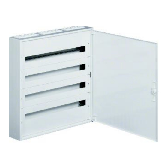
The wall-mounted enclosures are 150 mm deep. They are available in 5 different heights and 3 different widths. The Hager FW2 distribution board has its own internal mounting system, even if some parts, such as the door handle, come from the Univers system. - Page 7 For your safety Limitation of operating areas There are certain areas where the FW2 enclosure must not be used to prevent hazards or damage to the enclosure. The FW2 distribution box is not suitable for use: - in areas where a higher degree of protection is required - in areas where ATEX directives must be observed - in locations where there is a risk of fire - in corrosive environments.
-
Page 8: Requirements For Authorised Personnel
For your safety 2.2. Requirements for authorized personnel Only qualified electrically skilled persons may assemble, install, commission switchgear and controlgear assemblies, perform extensions, troubleshooting or maintenance and disassemble and dispose of them. The qualified electrically skilled persons must have appropriate experience in initial testing and subsequent commissioning, troubleshooting and maintenance. -
Page 9: Technical Data
Technical data & certification 3. Technical data 3.1. Technical features Intended use Observing the technical data is important for ensuring the intended use. Specifications for switchgear and control gear assemblies The FW2 distribution board is equipped with its own internal fitting system and is suitable as a switchgear and controlgear assembly according to EN 61439-1/-3 for: - Frequency fn = 50 Hz - Rated voltage Un = 230 / 400 V... - Page 10 Technical data & certification Dimensions Surface: A (mm) B (mm) C (mm) D (mm) FWx312Wx FWx412Wx FWx512Wx FWx612Wx 1091 FWx324Wx FWx424Wx FWx524Wx FWx624Wx 1091 FWx436Wx FWx536Wx FWx636Wx 1091 FWx736Wx 1241 1141 Wall mounting dims for surface enclosures Technical changes reserved...
- Page 11 Technical data & certification Flush: A (mm) B (mm) C (mm) D (mm) FW312Fx FW412Fx FW512Fx FW612Fx 1070 1142 FW324Fx FW424Fx FW524Fx FW624Fx 1070 1142 FW436Fx FW536Fx FW636Fx 1070 1142 FW736Fx 1220 1292 Wall mounting dims for flush enclosures Technical changes reserved...
- Page 12 Technical data & certification Mechanical installation of devices /internal fittings Equipped with FW2 internal fitting system Compatible with some specific univers Z and univers FW accessories (such as door components) Internal fitting system pre-assembled in all enclosures Protection class Protection class I (grounded) IP Protection Flush IP40 with door...
-
Page 13: Power Loss
Technical data & certification Power loss 3.2. 3.2.1. Power loss for surface enclosures Enclosure Permissible power loss P for enclosures without ventilation perm Temperature rise ΔT in flush mounted enclosures Height H Width W Depth D % of according IEC/TR 60890 Type enclosure 10 K... - Page 14 Technical data & certification 3.2.2. Power loss for flush enclosures Enclosure Permissible power loss P for enclosures without ventilation perm Temperature rise ΔT on wall mounted enclosures Height H Width W Depth D % of according IEC/TR 60890 Reference enclosure 10 K 15 K 20 K...
-
Page 15: The Fw2 Product Range
The FW2 board product range 4. The FW2 board product range 4.1 Delivery form The FW2 board is available in two delivery forms: Complete (flush and surface versions): Order number consists of cabinet, internal fittings and door (+ door frame by flush). FW524F FW636WT As individual parts (flush versions): First, the cabinet is ordered without a frame or door. -
Page 16: Coding
The FW2 board product range 4.2 Coding The FW2 Distribution board enclosure ordering number code consists of three components: - The enclosure type: FW324WT (FW+ 3 digits = FW2 board class I) - The enclosure dimensions 3 digits (height and width): FW324… (first digit = Height in number of rows, second and third digits = Width in number of modules) - The enclosure version: FW324WT (W = Wall-mounting, F= Flush-mounting, T= with PEN Terminals) -
Page 17: Overview Of Enclosure Product Codes
The FW2 board product range 4.3 Overview of enclosure product codes Size 3 Board width Flush 334 mm 550 mm 766 mm FW312F FW324F FW312FB FW324FB Board height FW312FBT FW324FBT 620 mm FW312FD FW324FD FW312FT FW324FT Surface 330 mm 545 mm 760 mm height FW312W... - Page 18 The FW2 board product range Size 6 Board width Flush 334 mm 550 mm 766 mm FW612F FW624F FW636F FW612FB FW624FB FW636FB Board height FW612FBT FW624FBT FW636FBT 1070 mm FW612FD FW624FD FW636FD FW612FT FW624FT FW636FT Surface 355 mm 571 mm 787 mm height FW612W...
-
Page 19: Enclosures In Detail
The FW2 board product range 5. Enclosures in detail 5.1. FWxxxF Product code FW312F FW324F FW412F FW424F FW436F FW512F FW524F FW536F FW612F FW624F FW636F FW736F Example: FW424F Internal fittings Distributor field: - Cover slots for 12, 24 or 36 modules - Distance between DIN rails 150 mm Without PEN terminals With frame and door:... -
Page 20: Fwxxxfb
The FW2 board product range 5.2. FWxxxFB Product code FW312FB FW324FB FW412FB FW424FB FW436FB FW512FB FW524FB FW536FB FW612FB FW624FB FW636FB FW736FB Example: FW524FB Internal fittings Distributor field: - Cover slots for 12, 24 or 36 modules - Distance between DIN rails 150 mm Without PEN terminals Without frame and door Included in the scope of delivery:... -
Page 21: Fwxxxfbt
The FW2 board product range 5.3. FWxxxFBT Product code FW312FBT FW324FBT FW412FBT FW424FBT FW436FBT FW512FBT FW524FBT FW536FBT FW612FBT FW624FBT FW636FBT FW736FBT Example: FW524FBT Internal fittings Distributor field: - Cover slots for 12, 24 or 36 modules - Distance between DIN rails 150 mm With PEN brass terminals: - Size 312, 412: 1x KM13N + 1x KM13E... -
Page 22: Fwxxxft
Enclosure features and accessories 5.4. FWxxxFT FW312FT FW324FT FW412FT FW424FT FW436FT FW512FT FW524FT FW536FT FW612FT FW624FT FW636FT FW736FT Example: FW536FT Internal fittings Distributor field: - Cover slots for 12, 24 or 36 modules - Distance between DIN rails 150 mm With PEN brass terminals: - Size 312, 412: 1x KM13N + 1x KM13E... -
Page 23: Fwxxxw
Enclosure features and accessories 5.5. FWxxxW FW312W FW324W FW412W FW424W FW436W FW512W FW524W FW536W FW612W FW624W FW636W FW736W Example: FW612W Internal fittings Distributor field: - Cover slots for 12, 24 or 36 modules - Distance between DIN rails 150 mm Without PEN terminals With door: - Plain... -
Page 24: Fwxxxwt
Enclosure features and accessories 5.6. FWxxxWT FW312WT FW324WT FW412WT FW424WT FW436WT FW512WT FW524WT FW536WT FW612WT FW624WT FW636WT FW736WT Example: FW624WT Internal fittings Distributor field: - Cover slots for 12, 24 or 36 modules - Distance between DIN rails 150 mm With PEN brass terminals: - Size 312, 412: 1x KM13N + 1x KM13E... -
Page 25: Frames And Doors Features And Accessories
Enclosure features and accessories 6. Frames and doors in detail 6.1. Features FW2 doors are similar to the FZxxx doors in the Univers range, but are 10mm longer and have different widths. Doors are compatible with FW2 flush- and surface mount boards. For all enclosure sizes, a single door can be mounted and closed with a 1-point latch with handle. - Page 26 Enclosure features and accessories Wall-mounted enclosures: The standard distance from the DIN rail to the door is 75mm and from the cover to the door 27mm. This must be taken into account when mounting modular equipment. The distance from the DIN rail to the door can be increased by 28mm by removing the 4 spacers.
-
Page 27: Fwxxxfd
Enclosure features and accessories 6.3. FWxxxFD Frames with doors for the flush enclosures are available by ordering the number code FWxxxFD. Product code FW312FD FW324FD FW412FD FW424FD FW436FD FW512FD FW524FD FW536FD FW612FD FW624FD FW636FD Example: FW524FD FW736FD Frame and Door only: Door: Plain Steel Door handle 90SL (FZ598) -
Page 28: Doors As Spare Parts
Enclosure features and accessories 6.4. Doors as spare parts Doors can be ordered as spare parts under following 77... numbers: Board Surface / Flush size Door product code FW312xx 770956800 770951900 FW324xx 770956900 FW412xx 770957200 FW424xx 770957400 FW436xx 770957000 FW512xx 770942600 FW524xx 770957500... -
Page 29: Door Accessories
Enclosure features and accessories 6.5. Door accessories 6.5.1. Door handle as spare part The standard door handle (90SL) is available as a spare part with product code FZ598. A sealing wire with a maximum diameter of 2mm can be inserted into the right hole (H) if the door needs to be sealed. -
Page 30: Enclosure Features And Accessories
Enclosure features and accessories 7. Enclosure features and accessories 7.1. Internal fittings Fitting structure Symmetrical, rotatable by 180° Composed of 2 vertical metal uprights with screwed DIN rails each 150 mm DIN rails are 35 mm wide and 15 mm high Internal fittings from FW312xx boards (flush and surface) Dismounting: The internal fittings can be dismounted by unscrewing the four 10 mm... - Page 31 Enclosure features and accessories Depth-adjustment: For the surface enclosures, it is also possible to mount the internal fittings 28 mm deeper by removing the four 13 mm hexagonal metallic spacers under the nuts. By doing this, the distance from the DIN rails to the door can be increased from 75 mm to 103 mm and the distance from covers to door from 27 to 55 mm.
-
Page 32: Accessories For Internal Fittings
Enclosure features and accessories 7.2. Accessories for internal fittings 7.2.1. DIN rails Additional DIN rails in 12, 24 and 36 module widths can be mounted on the internal fittings. These DIN rails are 7.5mm high, 35 mm wide and 284, 500 or 716 mm long. They are supplied with two M4 screws. - Page 33 Enclosure features and accessories 7.2.2. Covers and cover accessories Covers: The 12, 24 and 36 module wide 1-row metal covers can be ordered as a set of 2. They are available through the following internal product codes. Covers are always supplied with 2 screws.
- Page 34 Enclosure features and accessories Cover strips: Once the modular devices are installed, the remaining cover slots can be closed with the S35S (12 modules wide, 219 mm) or S35V (1000 mm wide) cover strips, which can be cut to the remaining width to be closed. S35S (219 mm) S35V (1000 mm) Marking strips:...
-
Page 35: Earthing Protection
Enclosure features and accessories 7.3. Earthing protection The earthing of the door can be made by connecting an earthing cable at door side. Top and bottom metallic covers are pre-perforated left- and right-hand side for passing an earthing cable through them. The earthing cable has to be connected on the other side with the with internal fittings A yellow Class I sticker is sticked on the internal fittings to indicate that it should be connected to the earth. -
Page 36: Cable Entries
Enclosure features and accessories 7.4. Cable entries 7.4.1. Cable entries top/bottom Flush boards Pre-punched cut-outs are located on the top and bottom areas of the flush board. The openings are the same size on the top/bottom and rear, making it easier to insert the board over the incoming cables (see photo below). - Page 37 Enclosure features and accessories As the cable entry plates and the housing are metallic, it is highly recommended that the metal edges be protected with an edge strip or tape to prevent damage to incoming cables. Surface boards The surface mount enclosures (W, WT) are equipped with flanges on top side. Depending on the desired cabling, it may be necessary to rotate the enclosure prior to wall mounting.
- Page 38 Enclosure features and accessories Flanges are made of smooth PE-LD plastic material and can be easily cut with a knife. Pipe diameters from the flange are listed below: 1x Ø13-36 mm 2x Ø6-29 mm 4x Ø10-16 mm 2x Ø9-20 mm 4x Ø6-10 mm The flange can be completely cut out along the inner groove (red line), so that an opening of 186x57 mm can be obtained.
- Page 39 Enclosure features and accessories 7.4.2. Side cable entries Flush boards FW2 flush boards include two pre-punched metal plates on the side for cutting out, resulting in a cable entry area of 90 x 60 mm for each opening. Side cable entries in flush board As for top/bottom cable entries, it is also highly recommended that the metal edges be protected with an edge strip or tape to prevent damage to incoming cables.
-
Page 40: Cable Strain Relief
Enclosure features and accessories 7.5. Cable strain relief Enclosure product codes ending with T such as FWxxxFT, FWxxxWT (T stands for Terminals) are delivered with 1 continuous metal rail for mounting the PEN clamps. The bar can be screwed to the top or bottom of the internal fittings. Several hooks are punched along the bar for fixing cables and pipes with cable ties. -
Page 41: Pen Terminals
Enclosure features and accessories 7.6. PEN terminals The FZ12H, FZ24H and FZ36H strain relief bars with brass terminals from the Univers product range are supplied with each FW2 board code with a T ending. Terminals can be ordered separately using the product codes KMxxE (PE, green) or KMxxN (N, blue). The two-digit xx indicates the maximum number of connections possible in the brass profile. -
Page 42: Inspection And Maintenance
- the specifications of the device or operating equipment manufacturer set forth in their instructions, - according to applicable national standards and regulations. Hager recommends performing a test at least once a year: - a visual inspection (external inspection), - switching operations of individual protective devices and switching devices (operation of RCD test buttons every six months), - document all tests, for example, in an inspection book. -
Page 43: Minimum Inspection/Maintenance Measures
Inspection and maintenance Recommended recurring tests System / operating Test interval Type of test Inspector equipment Electrical systems and Electrically 4 years For perfect working order stationary operating skilled person equipment (with testing experience) Electrical systems and Electrically 1 year For perfect working order stationary operating skilled... - Page 44 Inspection and maintenance External inspections, tests Test values, comments, remedy - Effectiveness of the ventilation system and Test the ambient conditions heating of operating space - Room temperature, relative humidity, aggressive air components, dust Accessibility, minimum distances Escape routes, clearances Visual inspection of covers and Damage that adversely affect the type of protection, such as:...
-
Page 45: Cleaning
- Do not use compressed air for cleaning - No wet cleaning - Remove all dirt - Hager offers a cleaning agent for plastic surfaces under order number VZ404 Technical changes reserved... -
Page 46: Decommissioning, Disassembly And Disposal
Decommissioning, disassembly and disposal 9. Decommissioning, disassembly and disposal 9.1. Decommissioning Decommissioning only by electrically skilled persons - Switch off the system - Observe the residual energies, residual voltages and residual heat - Disconnect the system and supply lines from all poles and on all sides - Secure against reconnection - Ensure that no voltage is present - Disconnect the supply line / incoming unit... -
Page 47: List Of All Product Codes
List of all product codes 10. List of all product codes Product Product Product Product Page Page Page Page code code code code 770942600 FW424F FW612FT S35S 770943300 FW424FB FW612W S35V 770943400 FW424FBT FW612WT UZ08Z1 770943900 FW424FD FW624F VZ404 770944500 FW424FT FW624FB 770944600... -
Page 48: Glossary
Glossary 11. Glossary EN 61439 / IEC 61439 / VDE 0660-600 The EN (IEC) 61439 series of standards aims to harmonise the rules and requirements for switchgear and controlgear assemblies. The valid part of the EN (IEC) 61439 standard series is always the applicable part of the standard, e.g. - Page 49 Glossary Distribution boards for operation by ordinary people (DBO) according to EN 61439-3 DBO: According to EN 61439-3, a DBO is a distribution boards for operating by ordinary persons (Distribution Board intended to be operated by ordinary persons). This is a switchgear and controlgear assembly for distributing electrical energy for applications in residential areas and other locations where operation is intended by ordinary persons.
- Page 50 Glossary IP Protection type / IP degree of protection The protection type indicates the suitability of electrical equipment, and therefore also of switchgear and controlgear assemblies, for use in different environmental conditions. For each switchgear and controlgear assembly, the protection type is specified with the IP code according to IEC 60529 and verified according to EN (IEC) 61439.
- Page 51 Index 12. Index About this manual • 3 Glossary • 47 Accessories • 28-40 Index • 50 Cable entries • 35-38 Inspection and maintenance • 41-43 IP protection type/IP degree of Cable strain relief • 39 protection • 49 Cleaning • 44 Coding •...
- Page 52 Hager Electro GmbH und Co. KG Zum Gunterstal 66440 BLIESKASTEL GERMANY Tel.: +49 6842 945 0 Fax: +49 6842 945 4625 E-Mail: info@hager.de www.hager.de Hager Support Hager Vertriebsgesellschaft mbH & Co. KG Zum Gunterstal 66440 BLIESKASTEL GERMANY Tel.: +49 6842 945-4460 Fax: +49 6842 945-4445 E-Mail: svb@hager.de...
Need help?
Do you have a question about the FW2 Series and is the answer not in the manual?
Questions and answers