Advertisement
Available languages
Available languages
Quick Links
ORIGINAL INSTRUCTION MANUAL
RETAIN FOR FUTURE REFERENCE
Accessory list
Att � ntion: : he drawings below are only for reference which might be slightly different from the actual object, please in kind prevail. Any tools missing
or 1nstallal1on problems, please conlact the customer service firstly.
�
x1
B
A
er
x4
x12
Allen key
Allen key
M8x50
M6x16
4x4
5x5
Part list
No.
Part
Qty
No.
Part
Qty
No.
0
®
1
G)
2
�
�
Column
0
®
®
1
1
�
�
Supporting beam
®
®
(j)
1
2
�
�box
®
1
(i])
4
�
�(ableti e
ltem No. : 402999/403000
Installation guide
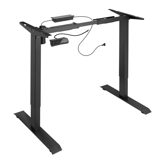
Technical data
2
Column Number
70KG
Maximum Load
25mm/s
Speed
100-240V
Input Voltage
710mm
Lowest Position
1210mm
Highest Position
1000-1600mmcw)
Desktop Size
500-800mmco)
Continuous operation for 2 mins at most after
Duty Cyde
oause for 1
mins
8
°
Applicable Temperature
0~40
F
r:Y4l
x15
Allen key
ST4.2x19
2.5x2.5
�
J
Installation instruction
Part
Qty
1
�
Column
6
2
�
�--
Supporting plate
1
STEP1
A
�
8
B
4
�
1
C
G
x1
Nut Wrench
STEP3
2
lnstall Pedestal(1)
2
lnstall (1) & (2)(3) together, use 5*5 wrench(C) to tighten the screws(A).
lnstall Supporting
beam(4)
2
4
2
Pis ad just the support beam size(4)
according to table top size.
Lay Column(2) down, just like picture 1 shows, then install (4), use wrench(C)
to tIghten the screws(B). lnstall Column(3) just as picture 2 shows.
lnstall Transmission rod(5)
1
2
Do not rotate the drive rod
more than a third of a turn.
lnstall (5) & (2)(3), following picture1 shows first, then
picture 2, use 2.5*2.5 wrench(D) to tighten.
3
C
Loose
�
Stretch
C
Tighten
�-
3
Advertisement

Related Manuals for TecTake 402999


Summary of Contents for TecTake 402999
- Page 1 STEP1 lnstall Pedestal(1) ltem No. : 402999/403000 � Installation guide ORIGINAL INSTRUCTION MANUAL RETAIN FOR FUTURE REFERENCE Technical data Column Number 70KG Maximum Load lnstall (1) & (2)(3) together, use 5*5 wrench(C) to tighten the screws(A). 25mm/s Speed 100-240V Input Voltage...
- Page 2 STEP4 How to use handswitch lnstall Supporting plate(6) [ lnstruction ] • Height A djustable Function: Button J Press the " •" or "'I'" button to ad just the height. The LED display shows the current height. • Height Memory Function: a.
- Page 3 Schritt 1 Montieren Sie den Fußausleger (1) Art.-Nr.: 402999/403000 � 1 nstal lationsan leitu ng ��A ' � . ÜBERSETZUNG DER ORIGINALBETRIEBSANLEITUNG FÜR KÜNFTIGE VERWENDUNG AUFBEWAHREN Technische Daten Anzahl der Säulen Montieren Sie (1) an (2)(3), indem Sie die Schrauben (A) mit dem Max.
- Page 4 Mon tieren Sie die Stü tzplat te (6) Schritt 4 [ Verwendung des Handschalters] • Höhenverstell-Funktion: [ Anweisung ] Drücken Sie die"-'-" oder die "T" -Taste, um die Höhe zu verstellen. Die LED-Anzeige zeigt die aktuelle Höhe. Taste • Höhenspeicher-Funktion: a.
-
Page 5: Liste D'accessoires
Etape 1 [ Montez le piedestal (1) ] � Article no. : 402999/403000 � � �� A Guide d'installation ' � . TRADUCTION DU MODE D'EMPLOI ORIGINAL A CONSERVER POUR UNE UTILISATION FUTURE Donnees techniques Colonne numero Montez (1) & (2)(3) ensemble, utilisez une cle 5*5 (C) pour serrer... - Page 6 Montez la plaque de support (6) Etape 4 [ Comment utiliser l'interrupteur manuel] • Fanctian de reglage en hauteur: [ lnstructions ] Appuyez sur la tauche "J." au "T" paur ajuster la hauteur. L'ecran LED affiche la hauteur en temps reel.
- Page 7 Paso 1 Monte la base de pie ( 1) Art.-Nr.: 402999/403000 � lnstrucciones de instalaci6n MANUAL DE INSTRUCCIONES DE USO DEL FABRICANTE TRADUCIDO CONSERVAR PA�A SER LEiDO POR CADA NUEVO USUARIO, ANTES DE UTILIZAR EL ARTICULO POR PRIMERA VEZ Datos tecnicos...
- Page 8 [ Monte la placa de apoyo Paso4 [ Uso del interruptor manual ] • Funci6n de ajuste en altura: [ lnstrucciones] Presione el bot6n ".l" o "T" para ajustar la altura. EI monitor LED muestra la altura en tiempo real. •...
-
Page 9: Guida All'installazione
PASSO1 Installare il piedistallo(1) ltem No. : 402999/403000 � Guida all'installazione CONSERVARE IL MANUALE DI ISTRUZIONI ORIGINALE PER RIFERIMENTO FUTURO Dati tecnici Numero di colonna 70KG Carico massimo Installare (1) e (2)(3) insieme, utilizzare la chiave 5*5(C) per serrare le viti(A). - Page 10 S.r.l. Via Manzano 70 Utilizzare le fascette per fissare tutti i cavi di 33040 Premariacco (UD) collegamento sulla scrivania per mantenerla Numero di telefono: +39 0471 1800175 pulita. E-Mail: mail@tectake.it...
Need help?
Do you have a question about the 402999 and is the answer not in the manual?
Questions and answers