Table of Contents
Advertisement
Quick Links
OPERATION MANUAL
WHISPERWATT™ SERIES
MODEL
DCA300SSJU4F3PB
60 Hz GENERATOR
(JOHN DEERE 6090HFG06 DIESEL ENGINE)
INSTRUCTION MANUAL NO. M5844300604
Revision #0 (12/10/24)
To find the latest revision of this publication or
associated parts manual, visit our website at:
www.mqpower.com
THIS MANUAL MUST ACCOMPANY THE EQUIPMENT AT ALL TIMES.
Advertisement
Table of Contents
Troubleshooting

Subscribe to Our Youtube Channel
Related Manuals for MQ Power WHISPERWATT DCA300SSJU4F3PB


Summary of Contents for MQ Power WHISPERWATT DCA300SSJU4F3PB
- Page 1 OPERATION MANUAL WHISPERWATT™ SERIES MODEL DCA300SSJU4F3PB 60 Hz GENERATOR (JOHN DEERE 6090HFG06 DIESEL ENGINE) INSTRUCTION MANUAL NO. M5844300604 Revision #0 (12/10/24) To find the latest revision of this publication or associated parts manual, visit our website at: www.mqpower.com THIS MANUAL MUST ACCOMPANY THE EQUIPMENT AT ALL TIMES.
-
Page 2: Proposition 65 Warning
PROPOSITION 65 WARNING PAGE 2 — DCA300SSJU4F3PB 60 HZ GENERATOR • OPERATION MANUAL — REV. #0 (12/10/24) -
Page 3: Table Of Contents
TABLE OF CONTENTS DCA300SSJU4F3PB NOTICE 60 Hz Generator Specifications are subject to change without notice. Proposition 65 Warning ........... 2 Table of Contents ............. 3 Safety Decals ............4 Safety Information ..........5–10 Specifications ............11 Dimensions ............12 Installation ............13–14 General Information .......... -
Page 4: Safety Decals
SAFETY DECALS SAFETY DECALS NOTICE Safety decals are attached to the generator as shown in For safety decal part numbers, refer to the associated Figure 1. Keep these safety decals clean at all times. When parts manual. the safety decals become worn or damaged, contact your nearest dealer or the Multiquip Parts Department. -
Page 5: Safety Messages
SAFETY INFORMATION Do not operate or service the generator before reading the Potential hazards associated with the operation of this entire manual. Safety precautions should be followed at all generator will be referenced with hazard symbols which times when operating this generator. Failure to read and may appear throughout this manual in conjunction with understand the safety messages and operating instructions safety messages. -
Page 6: General Safety
„ NEVER use accessories or attachments that are not being used. The generator should be stored in a clean, recommended by MQ Power for this generator. Damage dry location out of the reach of children and unauthorized to the generator and/or injury to the user may result. -
Page 7: Engine Safety
SAFETY INFORMATION ENGINE SAFETY „ Operation of the generator may create sparks that can start fi res around dry vegetation. A spark arrestor DANGER may be required. The operator should contact local fi re agencies for laws or regulations relating to fi re prevention „... -
Page 8: Fuel Safety
„ The trailer should be adjusted to a level position at all times when towing. „ Refer to the MQ Power trailer manual for additional safety information. „ Raise and lock the trailer wheel stand in the upright position when towing. -
Page 9: Electrical Safety
SAFETY INFORMATION ELECTRICAL SAFETY „ Make sure power cables are securely connected to the generator’s output receptacles. Incorrect connections DANGER may cause electrical shock and damage to the generator. „ NEVER touch the output terminals NOTICE during operation. Contact with the „... -
Page 10: Emissions Information
SAFETY INFORMATION EMISSIONS INFORMATION „ If the battery liquid (dilute sulfuric acid) comes into contact with eyes, rinse eyes immediately with plenty NOTICE of water and contact the nearest doctor or hospital to seek medical attention. The diesel engine used in this equipment has been designed to reduce harmful levels of carbon monoxide CAUTION (CO), hydrocarbons (HC), and nitrogen oxides (NOx) -
Page 11: Specifications
SPECIFICATIONS Table 1. Generator Specifications Model DCA300SSJU4F3PB Type Revolving field, self-ventilated, open protected type synchronous generator Armature Connection Star with neutral Phase Standby Output 264 kW (330 kVA) Prime Output 240 kW (300 kVA) 3Ø Voltage (L–L/L–N) 208Y/120, 220Y/127, 240Y/139 Voltage Change-Over Bd. -
Page 12: Dimensions
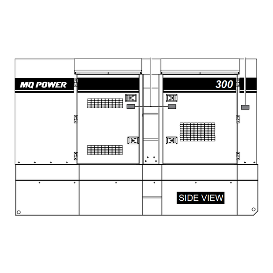
DIMENSIONS MAXIMUM LIFTING POINT TOP VIEW 19,000 lb. (8,618 kg) PowerBalance ® (Option) SIDE VIEW Figure 2. Dimensions FRONT VIEW Table 3. Dimensions Reference Dimension Reference Dimension Letter in. (mm) Letter in. (mm) 11.81 (300) 38.19 (970) 38.19 (970) 10.87 (276) 45.47 (1,155) 149.61 (3,800) 23.03 (585) -
Page 13: Generator Grounding
GENERATOR GROUND LUG GROUND ROD GROUND CABLE REFERENCE NEC 250 Figure 3. Typical Generator Grounding Application NOTICE Trailer-mounted generators are the sole responsibility of MQ Power. DCA300SSJU4F3PB 60 HZ GENERATOR • OPERATION MANUAL — REV. #0 (12/10/24) — PAGE 13... -
Page 14: Outdoor Installation
INSTALLATION OUTDOOR INSTALLATION MOUNTING Install the generator in an area that is free of debris, The generator must be mounted on a solid foundation bystanders, and overhead obstructions. Make sure the (such as concrete) and set firmly on the foundation to generator is on secure, level ground so that it cannot slide isolate vibration of the generator when it is running. -
Page 15: General Information
„ Control Box (located behind control panel) the generator. Refer to Table 2 for engine specifications. • Regen Inhibit Switch In keeping with MQ Power’s policy of constantly improving • AC Voltage Select Switch its products, the specifications quoted herein are subject •... -
Page 16: Load Sharing
GENERAL PARALLELING INFORMATION PARALLELING As the field excitation of one generator set in a group is decreased (i.e. over excited) it will not lead to a decrease Paralleling is the sharing of a load between two generator in voltage (as it would if it were operating alone) but it will sets or more. -
Page 17: Maintenance Interval
GENERAL PARALLELING INFORMATION MAINTENANCE INTERVAL Maintenance intervals are factory set for 250 hours. The maintenance interval timer will count down to zero indicating that it is time for the unit to be serviced. Once the timer counts down to zero, a pre-alarm will appear indicating that the unit is due for maintenance. -
Page 18: Major Components
MAJOR COMPONENTS Figure 4. Major Components Table 4. Major Components Item No. Description Item No. Description DEF Supply Module Assembly Digital Controller Assembly DOC/SCR Assembly Voltage Change-Over Board Assembly Air Cleaner Assembly Main Circuit Breaker Assembly Generator Assembly Emergency Stop Switch Assembly Battery Assembly Starting Fluid Cylinder Assembly Engine Assembly... -
Page 19: Control And Operation Panel
CONTROL AND OPERATION PANEL Figure 5. Control And Operation Panel The definitions below describe the controls and functions of the Control and Operation panel (Figure 5). 1. Regen Inhibit Switch — Press this button to inhibit 8. Control Power Switch — Set this switch to the ON regeneration in conditions where it may be unsafe position prior to operation. -
Page 20: Basler Digital Genset Controller
BASLER DIGITAL GENSET CONTROLLER LCD DISPLAY VOLT 60.0 HR : 3:58 DEF : 33 % 60 % 28.2 FUEL TEMP BATT Figure 6. Basler DGC-2020HD The definitions below describe the controls and functions of the Basler DGC-2020HD digital genset controller (Figure 6). 1. - Page 21 BASLER DIGITAL GENSET CONTROLLER 2. Not In Auto Indicator — This red LED lights when the 10. Run Pushbutton and Mode Indicator — Press this DGC-2020HD is not operating in Auto mode. button to place the DGC-2020HD in Run mode. The green Run Mode LED lights whenever Run mode is 3.
-
Page 22: Output Terminal Panel Familiarization
OUTPUT TERMINAL PANEL FAMILIARIZATION OUTPUT TERMINAL PANEL OUTPUT TERMINAL FAMILIARIZATION The output terminal panel (Figure 7) shown below is The output terminal panel is provided with the following: provided for the connection of electrical loads. Lift up on „ Three (3) 240/139-volt output receptacles @ 50 amps the cover to gain access to receptacles and terminal lugs. -
Page 23: Reset Button
OUTPUT TERMINAL PANEL FAMILIARIZATION 120-Volt AC GFCI Receptacles NOTICE It is recommended that the GFCI receptacles be tested when the generator is initially uncrated. The receptacles should then be tested daily at startup. SINGLE-PHASE CS-6369 240/139 VAC TWIST-LOCK There are two 120-volt, 20-amp GFCI (duplex NEMA 5-20R) 50-AMP OUTPUT RECEPTACLES receptacles provided on the output terminal panel. - Page 24 OUTPUT TERMINAL PANEL FAMILIARIZATION Connecting Loads Overcurrent Relay An overcurrent relay (Figure 12) is connected to the Loads can be connected to the generator via the output terminal panel, convenience receptacles, or optional main circuit breaker. In the event of an overload, both the cam-loks (Figure 11).
-
Page 25: Load Application
LOAD APPLICATION SINGLE-PHASE LOAD THREE-PHASE LOAD Always be sure to check the nameplate on the generator When calculating the power requirements for 3-phase and equipment to ensure the wattage, amperage, power, use the following equation: frequency, and voltage requirements are satisfactorily VOLTAGE ×... -
Page 26: Powerbalance
POWERBALANCE ® PowerBalance (Figure 13) is an optional load management ® solution that helps protect the engine generator from problems resulting from sustained low-load operations (defined as less than 30% of the generator full-load rating). POWERBALANCE ® ASSEMBLY Figure 13. PowerBalance ®... -
Page 27: Generator Outputs
GENERATOR OUTPUTS GENERATOR OUTPUT VOLTAGES AC VOLTAGE SELECT SWITCH Also located inside the control box is the AC Voltage Select A wide range of voltages (Table 7) is available for many different applications. switch (Figure 15). Use this switch to select either 240-volt output or 208-volt output when the voltage change-over Table 7. -
Page 28: Output Terminal Panel Connections
OUTPUT TERMINAL PANEL CONNECTIONS UVWO TERMINAL OUTPUT VOLTAGES 2. Make sure the AC Voltage Select switch (Figure 18) is placed in the 240-volt position. Various output voltages can be obtained using the UVWO output terminal lugs. The voltages at the terminals are dependent on the placement of the jumper plates (6) on 240V 208V... - Page 29 OUTPUT TERMINAL PANEL CONNECTIONS Single-Phase 240-Volt 3. Connect the load wires to the UVWO terminals as shown in Figure 23. UVWO Terminal Output Voltages 1. Make sure the voltage change-over board is jumpered BLUE GREEN WHITE BLACK for 240-volt operation as shown in Figure 17. 2.
- Page 30 OUTPUT TERMINAL PANEL CONNECTIONS Single-Phase 277-Volt 2. Connect the load wires to the UVWO terminals as shown in Figure 25. UVWO Terminal Output Voltages 1. Make sure the voltage change-over board is jumpered BLUE WHITE GREEN BLACK for 480-volt operation as shown in Figure 24. NOTICE The AC Voltage Select switch does not affect the voltage output while the voltage change-over board is...
-
Page 31: Engine Oil
INSPECTION/SETUP ENGINE OIL 5. If the engine oil level is low (Figure 29C), remove the cap from the oil filler port (Figure 30) and fill to a 1. To check the engine oil level, place the generator on safe operating level (max) as indicated by the dipstick secure, level ground with the engine stopped. -
Page 32: Fuel Check
INSPECTION/SETUP FUEL CHECK Refueling Procedure DANGER WARNING Diesel fuel and its vapors are dangerous Fuel spillage on a hot engine can cause a fire or explosion. If fuel spillage occurs, to your health and the surrounding environment. Avoid skin contact and/or wipe up the spilled fuel completely to prevent fire hazards. -
Page 33: Diesel Exhaust Fluid
INSPECTION/SETUP DEF Refilling 3. NEVER overfill the fuel tank. When refueling, DO NOT wait for fuel to rise inside the filler neck NOTICE (Figure 34). Leave room for fuel expansion. Fuel expands when heated (Figure 35). ONLY fill the DEF tank with diesel exhaust fluid. Any other type of fluid may cause severe engine damage. -
Page 34: Engine Air Cleaner
INSPECTION/SETUP Cleaning The Radiator Day-to-day addition of coolant is done from the reserve tank. When adding coolant to the radiator, DO NOT remove The engine may overheat if the radiator fins become the radiator cap until the unit has completely cooled. See overloaded with dust or debris. - Page 35 INSPECTION/SETUP Battery Cable Installation NOTICE ALWAYS make sure the battery cables are properly DO NOT put water directly on the alternator. Entry connected to the battery terminals as shown in Figure 38. of water into the alternator can cause corrosion and The red cable is connected to the positive terminal of the damage to the alternator.
-
Page 36: Before Starting
GENERATOR START - UP PROCEDURE ( MANUAL ) BEFORE STARTING CAUTION The engine’s exhaust contains harmful emissions. ALWAYS have adequate ventilation when operating. Direct exhaust away from nearby personnel. WARNING Figure 41. Circuit Breaker OFF Button (ON/RED) NEVER manually start the engine with the main, GFCI, or auxiliary circuit breakers in the ON (closed) position. - Page 37 GENERATOR START - UP PROCEDURE ( MANUAL ) 5. If the voltage is not within the specified tolerance, NOTICE use the voltage regulator (Figure 45) to increase or If the engine fails to start within 3 attempts, press the decrease the desired voltage. OFF button on the controller and place the battery DECREASE INCREASE...
-
Page 38: Generator Start-Up Procedure (Auto Mode)
GENERATOR START - UP PROCEDURE ( AUTO MODE ) STARTING (AUTO MODE) When starting the generator in Auto mode use the manual start-up procedure except where noted (see below). DANGER 1. Perform steps 1 through 6 in Before Starting found in Before connecting this generator to any the Generator Start-Up Procedure (Manual) section. -
Page 39: Generator Shutdown Procedures
GENERATOR SHUTDOWN PROCEDURES NORMAL SHUTDOWN PROCEDURE (AUTO) WARNING 1. Open the remote-start contacts. The circuit breaker will NEVER stop the engine suddenly except in an automatically turn OFF and the engine will stop after a emergency. 1-minute cool-down process. NORMAL SHUTDOWN PROCEDURE (MANUAL) 2. -
Page 40: Generator Start-Up Procedures (Parallel Operation)
GENERATOR START - UP PROCEDURES ( PARALLEL OPERATION ) GEN. 2 GEN. 3 GENERATOR 1 GEN. 1 GENERATOR 2 GEN. 2 GENERATOR 3 OUTPUT TERMINAL PANEL Figure 52. Communication Cable Connections (Parallel Operation) PAGE 40 — DCA300SSJU4F3PB 60 HZ GENERATOR • OPERATION MANUAL — REV. #0 (12/10/24) - Page 41 GENERATOR START - UP PROCEDURES ( PARALLEL OPERATION ) PARALLEL OPERATION (2 OR MORE UNITS) NOTICE NOTICE Use only category 5, 5e, 6, or 6e Ethernet cables with 8C8P modular connectors (RJ45 jacks) to To ensure stable operation of multiple generator units connect the units.
- Page 42 GENERATOR START - UP PROCEDURES ( PARALLEL OPERATION ) Starting (Manual) Starting (Auto) 1. Make sure the load’s ON/OFF switch is in the OFF 1. Make sure the load’s ON/OFF switch is in the OFF position. position. 2. Perform steps 1–4 of the Starting (Manual) section of 2.
- Page 43 GENERATOR START - UP PROCEDURES ( PARALLEL OPERATION ) Changing The Number Of Units 6. Check the voltage reading on the digital controller display (Figure 55). In Parallel Operation 1. If the load decreases during automatic parallel operation and the number of units involved in parallel operation needs to be decreased, push the Off button VOLT on the unit to be stopped.
-
Page 44: Generator Shutdown Procedures (Parallel Operation)
GENERATOR SHUTDOWN PROCEDURES ( PARALLEL OPERATION ) PARALLEL OPERATION SHUTDOWN PROCEDURE PARALLEL OPERATION SHUTDOWN PROCEDURE (MANUAL) (AUTO) 1. Place the load’s ON/OFF switch in the OFF position. NOTICE 2. Press the Circuit Breaker OFF button (Figure 56) on During parallel operation in Auto mode, the Circuit each generator in the paralleled system. -
Page 45: Maintenance
MAINTENANCE Every Every 3,000 Table 12. Inspection/Maintenance Hours 500 Hours or Hours or Other Hours or Daily 12 Months 36 Months Check Engine Oil and Coolant Levels Check Fuel Filter/Water Separator Bowl Check Air Cleaner/Element Clean or Replace Air Cleaner/Element Check for Leaks/Hoses/Clamps Check for Loosening of Parts Change Engine Oil and Oil Filter *... -
Page 46: General Inspection
MAINTENANCE Primary And Secondary Air Cleaner Elements GENERAL INSPECTION Every 250 hours: Remove the air cleaner elements and Prior to each use, the generator should be cleaned and clean them with a light spray of compressed air. inspected for deficiencies. Check for loose, missing, or damaged nuts, bolts, or other fasteners. -
Page 47: Engine Fuel Filter
MAINTENANCE Air Cleaner Restriction Indicator ENGINE FUEL FILTER The air cleaner is equipped with a restriction indicator Inspect the engine fuel filter daily. If the fuel filter has (Figure 60). As the air cleaner element becomes clogged, collected a significant amount of water and sediment at air intake restriction increases and the indicator signal the bottom of the cup, it should be drained off immediately. - Page 48 MAINTENANCE Fuel Filter Element Replacement Fuel Water Separator Sediment Bowl 1. Using a filter wrench, remove the fuel filter cartridge 1. Remove the sediment bowl (Figure 64) from the fuel from the filter head (Figure 63). water separator cartridge. FILTER HEAD RETAINING RING...
-
Page 49: Fuel Tank Inspection
MAINTENANCE Fuel Water Separator Replacement CLEANING INSIDE THE FUEL TANK 1. Using a filter wrench, remove the fuel water If necessary, drain the fuel inside the fuel tank completely. separator cartridge (Figure 65) from the cartridge Using a spray washer (Figure 66), wash out any deposits head. -
Page 50: Draining The Engine Oil
MAINTENANCE DRAINING THE ENGINE OIL ENGINE OIL FILTER REPLACEMENT NOTICE 1. Run the engine until the engine coolant reaches a temperature of 140°F (60°C). Filter head appearance may vary. 2. Turn the engine OFF. 1. Clean the area around the oil filter head (Figure 68). 3. - Page 51 MAINTENANCE DRAINING THE ENGINE COOLANT FLUSHING OUT THE RADIATOR AND REPLACING COOLANT WARNING WARNING DO NOT remove the pressure cap from the radiator while the engine is hot! Wait until the coolant Allow the engine to cool before flushing temperature is below 120°F (50°C) before removing out the radiator.
-
Page 52: Radiator Cleaning
MAINTENANCE RADIATOR CLEANING The radiator (Figure 71) should be sprayed (cleaned) with DRIVE BELT a high-pressure washer when excessive amounts of dirt and debris have accumulated on the cooling fins or tube. When using a high-pressure washer, stand at least 5 feet (1.5 meters) away from the radiator to prevent damage to the fins and tube. - Page 53 MAINTENANCE TESTING THE GFCI RECEPTACLE 5. Press the RESET button (Figure 76) to restore power to the GFCI receptacle and verify that the status LED NOTICE is ON (GREEN). The GFCI receptacle is designed to interrupt power when a ground fault exists to prevent injuries and shock hazards.
- Page 54 MAINTENANCE ENGINE BLOCK HEATER AND When using the generator in hot climates there is no reason to apply power to the engine block heater. However, if the OPTIONAL INTERNAL BATTERY CHARGER generator will be used in cold climates it is always a good 120 VAC INPUT RECEPTACLES idea to apply power to the engine block heater at all times.
-
Page 55: Emission Control
MAINTENANCE PREVENTIVE MAINTENANCE PROGRAMS EMISSION CONTROL The emission control system employed with this diesel Most challenging to a rental organization is the fact that a engine consists of a diesel oxidation catalyst (DOC) customer’s power assumptions may not meet the minimum and a selective catalytic reduction (SCR) catalyst load requirements of the power equipment selected. -
Page 56: Selective Catalytic Reduction (Scr)
MAINTENANCE SELECTIVE CATALYTIC REDUCTION (SCR) Regeneration Guidelines Diesel engines can be run with a lean burn air-to-fuel For the safe operation of equipment, protection of the ratio, to ensure the full combustion of soot and to prevent surrounding area, and prevention of bodily harm, use the the exhaust of unburnt fuel. - Page 57 MAINTENANCE Automatic Regeneration 1. Make sure the Circuit Breaker OFF button LED is ON (red). See Figure 82. DO NOT load the generator When enough DEF deposits accumulate in the system, during forced regeneration. the automatic DOC/SCR regeneration process will occur automatically.
-
Page 58: Diesel Exhaust Fluid (Def)
MAINTENANCE DIESEL EXHAUST FLUID (DEF) DEF INDICATOR The amount of fluid in the DEF tank will be displayed on the digital controller during operation (Figure 84). Pre-Alarm Active DEF Fluid Low PA LEVEL Fuel 29 % DEF: 8 % VOLT 60.0 HR : 3:58 DEF : 33 %... -
Page 59: Diagnostic Mode
TROUBLESHOOTING ( DIAGNOSTICS ) DIAGNOSTIC MODE The digital controller can be placed in Diagnostic mode, which will keep the key switch on for service tool purposes. To place the unit in Diagnostic mode the engine must be turned OFF. 1. Press the Alarm Silence button and the Lamp Test button (Figure 86) simultaneously for 5 seconds. -
Page 60: Protection Devices
Allow a sufficient cooling period, then inspect the unit and repair the problem before restarting operation. If necessary, contact your nearest MQ Power dealer for additional technical support. When the unit is ready to restart, press the Off button on the digital controller. - Page 61 TROUBLESHOOTING ( DIAGNOSTICS ) Table 14. Automatic Engine Shutdown System Operating Circuit Breaker Engine Digital Controller Display Operating Condition/ Parameter Off LED Shutdown Message Set Point Under Voltage 27P-1 UndVolt Alarm Set point: 408 V Over Voltage 59P-1 OvrVolt Alarm Set point: 528 V Under Frequency —...
-
Page 62: Troubleshooting (Generator)
TROUBLESHOOTING ( GENERATOR ) Practically all breakdowns can be prevented by proper handling and maintenance inspections, but in the event of a breakdown, use Table 15 for diagnosis of the generator. If the problem cannot be remedied, consult our company’s business office or service plant. -
Page 63: Troubleshooting (Engine)
TROUBLESHOOTING ( ENGINE ) Troubleshooting (Engine) Symptom Possible Problem Solution No fuel reaching injection pump? Add fuel. Check entire fuel system. Defective fuel pump? Replace fuel pump. Fuel fi lter clogged? Replace fuel fi lter and clean tank. Faulty fuel supply line? Replace or repair fuel line. - Page 64 TROUBLESHOOTING ( ENGINE ) Troubleshooting (Engine) - continued Symptom Possible Problem Solution Air fi lter blocked? Clean or replace air fi lter. Low engine power output and low speed, Incorrect valve clearances? Adjust valves per engine specifi cation. black exhaust smoke. Malfunction at injector? See engine manual.
-
Page 65: Generator Wiring Diagram (M5814000903A)
GENERATOR WIRING DIAGRAM ( M5814000903A ) DCA300SSJU4F3PB 60 HZ GENERATOR • OPERATION MANUAL — REV. #0 (12/10/24) — PAGE 65... -
Page 66: Engine Wiring Diagram (M5814101303A)
ENGINE WIRING DIAGRAM ( M5814101303A ) PAGE 66 — DCA300SSJU4F3PB 60 HZ GENERATOR • OPERATION MANUAL — REV. #0 (12/10/24) -
Page 67: John Deere Wiring Diagram (M5814101403)
JOHN DEERE WIRING DIAGRAM ( M5814101403 ) DCA300SSJU4F3PB 60 HZ GENERATOR • OPERATION MANUAL — REV. #0 (12/10/24) — PAGE 67... -
Page 68: Mcb Sequence Diagram (M5814200103)
MCB SEQUENCE DIAGRAM ( M5814200103 ) PAGE 68 — DCA300SSJU4F3PB 60 HZ GENERATOR • OPERATION MANUAL — REV. #0 (12/10/24) -
Page 69: Battery Charger Wiring Diagram (Option)
BATTERY CHARGER WIRING DIAGRAM ( OPTION ) BLACK 14 AWG. LINE (L)120VAC INPUT WHITE 14 AWG. NEUTRAL (N) GREEN 14 AWG. GROUND (G) TO CHASSIS GROUND GREEN 16 AWG. TO STARTER “B” TERMINAL RED 16 AWG. 120 VAC INPUT, INSERT EXTERNAL POWER CORD HERE. -
Page 70: Here's How To Get Help
© COPYRIGHT 2024, MULTIQUIP INC. Multiquip Inc , the MQ logo and the MQ Power logo are registered trademarks of Multiquip Inc. and may not be used, reproduced, or altered without written permission. All other trademarks are the property of their respective owners and used with permission.
Need help?
Do you have a question about the WHISPERWATT DCA300SSJU4F3PB and is the answer not in the manual?
Questions and answers