Advertisement
- 1 Check Packaging
- 2 Front/Back Panel Diagrams & Descriptions
- 3 Hardware Setup
- 4 Console Setup
- 5 Main Menu overview
- 6 Motion Detection & Recording Setup
- 7 Accessing Playback
- 8 How To Upgrade System Firmware
- 9 Computer Access Setup
- 10 Accessing the Web User Interface
- 11 Troubleshooting steps
- 12 Web Interface Walkthrough
- 13 Amcrest View Pro App Setup
- 14 Important Safeguards and Warnings
- 15 References & Contact Information
- 16 Documents / Resources
Check Packaging
When you receive the system, unpack it, and check all sides of the DVR to see if there is any damage to the unit. The protective materials used for the packaging of the DVR can protect most accidental damage during transportation, but to ensure that your equipment is operating as expected, it is recommended to inspect the product before proceeding further.
On the DVR unit, please verify that the label on the bottom of the DVR is not damaged. The serial number of the unit is often needed to provide support or other functions such as connecting to the Amcrest View Pro app.
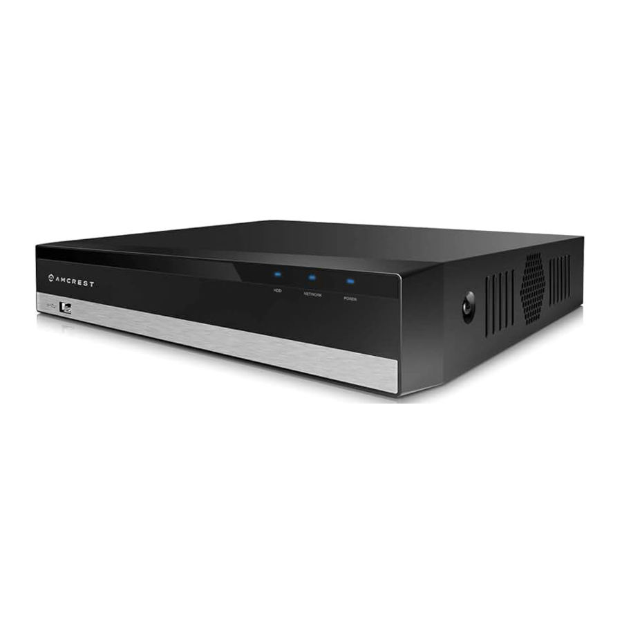
Front/Back Panel Diagrams & Descriptions
Front Panel

Please refer to the following chart for information on the front panel buttons.
| Icon | Name | Function |
| NET | Network abnormality indicator light | When a network error occurs or there is no network connection, this light turns red. |
| PWR | Power indicator | When DVR is on, this light remains on. |
| HDD | HDD abnormal indicator light | When an HDD error occurs, or the HDD capacity is below the specified threshold value, this light turns red. |
 | USB 2.0 Port | USB 2.0 port: connect a mouse, USB storage device, etc. |
Rear Panel

Please refer to the following chart for detailed information on the rear panel ports:
| Port Name | Function |
| Video Input Port | Connects to analog camera to input video signal. |
| Audio Input Port | Receives audio signal output from an RCA microphone DVR. |
| Audio Output Port | Output's audio signal to an external RCA speaker. |
| HDMI Port | High-definition audio and video signal output port. The port outputs an uncompressed high-definition feed as well as multichannel audio data to a connected HDMI compatible display. |
| USB Port | Connects to an external DVR such as, a mouse, keyboard, or external USB storage DVR. |
| Ethernet Port | Connects an Ethernet cable to the network. |
| A/B Port | Connects to a control device such as PTZ. RS-485_A port is connected by the cable "A" and RS-485_B is connected to the cable "B". |
| VGA Port | Outputs analog video data to a connected display with a compatible VGA port. |
| Power Input Port | Inputs DC 12V power. |
 | Ground terminal. |
| Power Cable Fastener | Use a clamp to secure the power cable on the DVR to avoid signal error. |
Hardware Setup
Before setting up the DVR, you will need the following items.
The items are not included:
A computer monitor or TV with either an HDMI or VGA input
A power strip with room for 4 large power plugs
It is recommended to connect all components of the system as shown below before mounting any of the cameras. This is to ensure all components are working before any physical installation takes place. If any components are not functioning, please contact Amcrest Support at https://amcrest.com/contact or by giving us a call at 888-212-7538.
Setting up the cable connections
The following instructions will show you how to set up the cables for the DVR, cameras, as well as a monitor or TV screen.
- Connect a monitor or TV screen to your DVR. For purposes of this guide, we will use a VGA connection. Take a VGA cable, and connect one end to the VGA port on your monitor/screen and the other end to the VGA port on the back panel of your DVR.
- Connect the included USB mouse to the front of the DVR.
- Connect an Ethernet cable to your router and connect the other end of the Ethernet cable to the Ethernet port on the back of the DVR.
- Plug the included power adapter into the power port on the back of the DVR and plug the power adapter into a wall outlet or surge protector. Allow the DVR to power up. Please note, the DVR will beep if a hard drive (sold separately) is not installed, for more information on how to install a hard drive, please refer to"Hard Drive Installation".
- Secure the BNC connection on the coaxial cable to the BNC video connection on the camera then connect the power connection to the power port of the camera.
- Secure the other BNC connection from the camera to a video (coaxial) ports on the back of the DVR and connect the power adapter to the power port found on the BNC cable.
PLEASE READ BELOW
Note: Your DVR may not work properly if the following is not accounted for.
Every DVR comes preset to a video output resolution of 1280x1024. What this means is that any time an HDMI cable is plugged into an HDTV, it may result with a blank screen even if the DVR is working properly.
If this occurs, please follow the steps below.
Procedure using a VGA cable:
- Connect your DVR to a computer monitor or TV screen with a VGA cable (the HDMI cable should not be connected during this process).
- Boot up the unit. On the monitor or TV, please make sure the "input" is set to VGA.
- When the interface loads, you will see the login screen. Enter the login credentials for your DVR. If this is your first-time logging into your unit, the default username and password will be admin.
- Once you have logged into your DVR, navigate to the section that says Display. The display menu allows you to configure resolution and display settings.
- Then, on the new window, change your resolution from 1280x1024 to 1920x1080. Once complete, scroll down to the bottom and click on Save to save your display settings. Your DVR will reset to effect the change.
- Disconnect the VGA cable and connect your DVR to an HD monitor or TV using an HDMI cable. Do not forget to change the input to HDMI on your TV/monitor. The DVR will load, and you will be able to properly use the unit on your screen.
Hard Drive Installation
A hard drive allows you to configure and store recordings from the DVR, this includes playing back previously recorded footage.
Note: This section only applies to DVRs purchased without a hard drive already preinstalled. Most 'kits' or 'bundles will come with a pre-installed hard drive.
The DVR has connections for only 1 hard drive inside the case and the hard drive must be no bigger than 10TB (Terabytes).
To install your hard drive, the following is needed:
A medium sized (regular) Phillips-head screwdriver - not included
A hard drive - not included (unless you purchased a 'kit' that does have one included)
Four hard drive fastening screws - included
Note: Before installing the hard drive, make sure the DVR is powered off and completely disconnected from power.
|
|
|
|
|
|


Once the hard drive is installed, turn on the DVR. If the hard drive for your DVR was not setup properly you may hear a beeping noise. This indicates the DVR does not have the proper connection with your hard drive.
Console Setup
Device Initialization
After turning the system on, the default video display will show multiple windows and a device initialization page will appear. Follow the on-screen prompts to complete initialization.
Password Setting
The first thing you will need to do in the setup process is create a new admin password for your device. The password for your device should be between 8 and 32 characters with a combination of letters, numbers, and symbols are recommended.
Note: Please do not use special symbols like ' "; : &

Once you have entered a new password for your device, confirm the password in the next field
Please note that the system consists of two accounts (out of the box):
Username: admin Password: admin (administrator, local and network)
Username: default Password: default (hidden user)
Lastly, you will be asked to enter a prompt question for your account. This is useful if you have forgotten your password and would like an easier means of recovering your password. Please use a prompt question what will help you remember the password for your device.
After you have completed this section, click Next to continue.
Unlock Pattern

This is an optional security measure for your device. You can also assign an unlock pattern for your admin account. To set an unlock pattern, using your mouse, draw a design which you will remember to access your device. If you do not wish to assign an unlock pattern, you can click "Skip" to skip this process.
If you have assigned an unlock pattern, you will need to draw the pattern again to confirm the validity of your assigned unlock pattern.
Password Protection
Additional means of password protection and retrieval can be set up in this menu. If you would like to reset your password via email, toggle the toggle switch to the on position and enter a valid email address in the Email Address field. The email address will be retained in the system.

If you do not wish to use an email address, you can enter security questions. To enable security questions, click the toggle switch to the on position in the Security Questions field. Select a question from the drop-down menus for Question 1, Question 2, and Question 3 and enter the answers to those questions in the Answer fields.
Once this section is complete, click on the OK button to save your information to the device.
Startup Wizard Walkthrough
The first page of the Startup Wizard will appear.
If you do not want to use the Startup Wizard, or you have already gone through it and do not want it to keep appearing, unmark the checkbox next to Startup and click Cancel.
Note: Every page from the Startup Wizard that follows can be accessed and modified at any time through the Main Menu. To login to the system, click Next.
Basic

The Basic screen allows you to set a language, video standard and other basic settings for the DVR. Once you are satisfied with the settings on this screen, click the Next button at the bottom of the screen.
Date & Time
The next screen that appears will be the Date & Time settings screen. This is where you can set the date and time for your specific location. If you wish to utilize daylight savings time, toggle the DST toggle switch to the on position. Once you have selected the proper date and time for your device, click the Next button to continue.

Note: Make sure to toggle the NTP toggle switch to the off position to avoid syncing your device to the NTP server.
TCP/IP

The next screen that will appear is the TCP/IP screen. This screen allows the user to configure the network settings. If you want to set your device up to have a static IP, toggle the DHCP toggle switch to the off position.
Note: To test the connectivity of the device to your network, click on the Test button. The device will return a network status. To return to the previous menu, click the Back button.
P2P
The next screen that appears is the P2P settings screen. This will be enabled by default. It is highly recommended to keep this enabled if you want to use, you are the Amcrest View Pro mobile app or AmcrestView.com to view your cameras remotely.
After enabling the P2P toggle switch, click the Next button to continue.
Audio/Video
This is where you can adjust the video quality settings for your DVR/cameras, including the compression and frame rate. To access or adjust audio formats, click on the More tab. Click on the Next button to continue.
Snapshot
The next screen that will appear will be the Snapshot settings screen. This is where you can adjust the settings for your snapshots. This includes, the image size, quality, as well as interval in which the snapshot is retained. Once set, click on the Next button to continue.
Basic
The next screen that will appear will be labeled Basic. This is where you can configure your hard drive settings including, when to overwrite a full hard drive. The device will be set to not overwrite files by default, however, this can be adjusted using the Custom option. Select custom and use the number pad to enter the number of days that will be applicable until the expired files are deleted. Click Next to continue.
Record
The next screen you see is the Record settings screen. Your DVR is configured, by default, to record everything on all channels 24/7 (this will only actually happen provided you have a hard drive installed). You can also use this screen to set up motion detection and alarm schedules.
Once you are satisfied with the settings on this screen, click the Next button at the bottom of the screen.

Next you will be able to configure your snapshot settings for your scheduled recordings. You can also use this screen to set up motion detection and alarm schedules for snapshot events. Once you have scheduled your events, click on the OK button to continue. Follow the on-screen prompts to finish the setting up the DVR. Once complete the video wall will be displayed. Left click on the video wall and click on Main Menu to access the main menu.
Main Menu overview

The screenshot above is the main menu screen for the Amcrest DVR console interface:
Below are short descriptions for each of the menu items on the main menu:
LIVE: Access the live view screen and display a video wall for each connected device.
SEARCH: Search and playback recorded video that is stored on the hard drive.
ALARM: View and configure live alarm information and notifications sent by the device.
AI: This menu allows you to manage and view artificial intelligence features such as, SMD (smart Motion detection), face detection, face recognition, and IVS&SMD, as well as smart search features. Please note, due to certain limitation, only one AI mode can be activated at a time in the DVR. For more information on the features listed in this menu, please refer to section, "Setting Up AI Events".
MAINTAIN: View system information, update, and configuration import/export settings, etc.
BACKUP: Search and backup video data via an external USB or flash drive.
DISPLAY: Configure resolution and display output settings.
AUDIO: Schedule, manage, and import audio announcements and files.
Management
CAMERA: Review or edit settings for each camera, including video settings (e.g. quality, bit rate, color, etc.).
NETWORK: Review or edit network settings for the DVR (e.g. email, DDNS, UPnP, etc.)
STORAGE: Review or edit storage parameters and settings. (e.g. motion detection, alarm, etc.). Set HDD detection as well as setup FTP settings.
SYSTEM: Review or edit system parameters or configuration, including system maintenance, factory resets and firmware upgrades.
SECURITY: Review and configure trusted and blocked sites using the onboard IP filter (Firewall).
ACCOUNT: Review admin accounts and add new users to device. (e.g. ONVIF users).
Connecting an IP Camera
This is optional however, please note, adding an IP camera to the DVR, will conflict with AI features. The number of IP cameras added to the DVR will be dependent on how many channels your specific model supports. The DVR will be provided with specific channels for IP cameras, typically towards the bottom of the channel list and will not replace an active analog channel in the DVR. To connect an IP camera to your DVR, please follow the steps provided below:
- Click on the Camera option located in the Management section of the Main Menu.
- Click on Channel Type and select the IP channels from the IP column of the list.
- Click on Apply. A prompt will appear, click OK and allow the DVR to reset.
- Navigate back to the Camera menu and click on Camera List.
- Click on Device Search to search for the IP camera you want to add and click on the enable checkbox.
- Click on the Add button to add the IP Camera to the DVR. If the camera has an inactive status (red dot) the password may need to be updated
Updating the Password (IP Camera)
Click on the Modify button.
Ensure your camera settings are properly set and enter the password for your newly added IP Camera. If this is your first time using your camera the username and password will be admin.
Click on Save to save the settings to your camera. If all information was entered correctly, the indicator icon in the Status field will be green.
Motion Detection & Recording Setup
This section will cover how to set up your DVR's scheduled recordings for both regular and motion detection recordings. It will also cover how to set up email alerts with snapshots.
Note: The DVR can only be set up to save regular and motion detection recordings if a hard drive has already been installed. However, email alerts with snapshots can still work without a hard drive installed.
A hard drive is included with every DVR 'kit' purchased. You can confirm this by looking at the packaging. If bought as a standalone DVR, a hard drive will need to be purchased separately.
The following setup processes will be shown using the DVR console's built-in interface. However, these same steps can also be done through the web interface on a computer. Despite the difference in appearance, the settings pages have the exact same organizational structure.
Setting up recording schedules
- Log into your DVR with your username and password:
- Open the MAIN MENU, then click STORAGE in the MANAGEMENT row:
- Make sure you are on the SCHEDULE > Record page.

- Choose a channel (camera) to configure by selecting a channel from the Channel dropdown menu. If you would like the schedule to apply to all channel, click All.
- By default, the DVR will have the schedule configured to record 24/7 on each record type. Please note, the DVR uses military time which goes from 0 to 24 hours.
To change which hours, you would like to record, select the record type you wish to modify, in this example we are using the GENERAL record type, then click the time blocks in the grid. You can also click and drag to add or remove multiple blocks at a time. Each block represents one hour.
Note: Click the eraser icon to the right of any day to clear the entire row of blocks.

- To add or remove motion detection blocks, click on the checkbox next to Motion, then click the individual cells on the grid or click and drag for multiple blocks.

- To the left of each day, there are small boxes which can be marked to "link" different days together. This is useful if you want to save time by instantly making changes to multiple days simultaneously.
In the below example, Sunday and Monday are linked, so any blocks that are added or removed for Sunday will automatically and immediately reflect the same for Monday and vice versa.

- Another way to configure recording schedules is by setting the time periods. Click the 'gear' icon to the far right of any day to open the Period page:
Here, the periods (Periods 1 - 6) must be in specified in chronological order. You can set either record type to a specified period. Make sure to click OK when finished. Please note, in this example we set the general record type to record in 3 periods, the motion detection in 1 period, and the IVS (AI recording type) to apply to each period.

- Now that you have finished configuring the recording schedules, you may need to copy these settings over to other channels (cameras). By default, Channel 1 will be selected when you visit this page. Unless you immediately selected All in the channel window from step 4 above, note that you can copy these settings directly over to another channel by clicking Copy to down below:
In the Copy window, you can select individual channels for any cameras you have added to the DVR or select All. Click OK when finished.

- When finished on this screen, click Apply to save your changes.


Setting Up Motion Detection and Email Alerts
Your DVR will save motion detection recordings, in addition to scheduled 'regular' recordings and distinguish between the two in the playback menu.
- Log into your DVR with your username and password:
- Open the MAIN MENU, and click the ALARM tab.
- In the alarm menu, click on VIDEO DETECTION. This is the main configuration page for motion detection:
Change your channel (or camera) by clicking Channel and selecting from any cameras currently added to the DVR. You can also select All. Make sure the Enable toggle switch is activated. Then, click Setting to Region to configure the motion detection areas.

- You can set up 'regions' for motion detection using the region grid on your DVR.
By default, the entire area of view for your cameras will be highlighted with red blocks. This means that the entire field of view is active for motion detection.
Any red blocks that you click or click-and-drag to remove will not be active for motion detection. Motion detection will not work for any portion of the screen that is clear.
If you hover your mouse pointer over the top-center edge of this window, another small window will appear with options to configure sensitivity and threshold settings as well as to choose from up to four regions.

Sensitivity - is the measure of how many pixels on the screen need to change before being considered motion. 0 is the lowest value and 100 is the highest.
In plain English: Sensitivity is the difference between a squirrel running up a tree, versus a big dog running up to and barking at that tree. A squirrel would trigger motion detection at a higher sensitivity because it takes less change or movement to qualify as motion. But the dog would trigger motion detection at a lower sensitivity because it takes more change or movement to qualify as motion.
Threshold - is the degree of movement that needs to occur before the motion is defined as a motion event and is triggered. 0 is the lowest value and 100 is the highest.
In plain English: Threshold is the difference between a car driving quickly by on a street and a car driving into the field of view, slowing down, and turning into a driveway. The car driving past would not trigger motion detection based on a certain threshold setting, but the parking car would trigger motion detection with that same threshold setting. The higher the threshold, the more time motion needs to occur before motion detection is triggered. The lower the threshold, the less time motion needs to occur before motion detection is triggered.
If sensitivity is set to 100 and threshold to 0, motion detection will be triggered most easily by almost any change in the field of view, large or small. But if sensitivity is set to 0 and threshold to 100, motion detection will be extremely difficult to trigger.
The four regions are all different colors so you can customize the field of view of any camera to your highly specific preferences.
- To choose another region, hover your mouse pointer near the top-center of the region window, and a small window will appear. Keep your mouse pointer inside that small window and select either region 2, 3, or 4:
You will be able to click individual blocks or click-and-drag an area with the new selected color to highlight portions of the screen. Each new region (or color) has its own unique sensitivity and threshold settings. The different regions/colors can also overlap one another.

- You can also adjust the motion detection schedules directly from this settings page by clicking Setting next to Period.
The Schedule page works very similarly to the recording schedule page featured in the previous section of this guide. - Next, if you want to receive email alerts of your motion detection events, check the Send Email box.
- Once you have set up your settings for one channel, you can copy them to another channel. If you did not select All after clicking Channel as described in step 3, click Copy, select channels to copy to, then click OK.
- Click Apply to save all the settings made on this page.

Setting Up Email Alerts
- Next, go back to the main menu and click the NETWORK tab on the bottom row. In the Network menu, click on EMAIL from the left navigation panel:


The recommended method for this step is to create a new Gmail account that is dedicated to sending you email alert snapshots for motion detection. This is useful because then, you do not have to change any of your own personal email's settings. Using a Gmail account is also the easiest way to set up email alerts which could otherwise be somewhat technical and difficult.
This does not mean that you now must log into a second, separate email account just to see your email alerts - because this email will forward all your email alerts to your personal email. Regardless, it is still recommended to save your email and password information for this new Gmail account.
Start by making sure the Enable toggle switch is toggled to the on position. Then, enter the SMTP Server which, for Gmail, is: "smtp.gmail.com". The port number will be: "465".
In the Username field, enter your new Gmail account's address. For example: "amcrestemailsme@gmail.com". Then, enter the password for this account in the Password field.
In the Email Address field, enter your own personal email account's address. For example: "amcrestemailsme@gmail.com". In the Sender field, enter your email address again. Make sure the toggle switch for the Attachment is toggled to the on position. Then, make sure the Encryption Type field is set to "SSL".
Finally, click Apply in the bottom-right of this window to save all your settings.
- Now, we want to make sure the email setup is working properly. To do this, clickTest in the bottom-left. If the setup was successful, you will get the "Mail Test Normal" pop-up message after clicking Test.
- Next, check your new Gmail account to see if you received the email test. Whenever your camera detects motion, you will get email alerts sent to your personal email from this new Gmail account.
This will include an email with a snapshot of what was seen when motion detection was triggered.
Setting Up AI Events
This section will cover the basic setup of AI events provided by the DVR. The features listed in the AI menu include SMD (Smart Motion Detection), Face Detection & Recognition, as well as IVS & SMD which function independently in the system.
- Log into your DVR and on the Main Menu, click on AI.

- Select a feature from the AI Mode menu. Please note, after an AI mode is selected, the DVR will reboot, please allow the device to reboot once an AI is selected.
SMD – Allows the device to use smart motion detection to detect between human and motor vehicles.
Face Detection & Recognition - Face detection is used to allow your device to detect and record face image events. Face recognition is used in conjunction with face detection to locate and determine facial similarities detected by the system. Images are registered in a face library, by the user, and accessed via a face recognition smart search tool that is built into the DVR. The DVR supports a max of 2 face detection & face recognition channels.
IVS&SMD – IVS stands for intelligent video system analytics and are primarily used for parameter protection. The DVR currently has 2 built-in IVS features available (Tripwire and Intrusion). Smart Motion Detection (SMD) uses an advanced algorithm to differentiate human and vehicular shapes within a scene and send alarms only when a person or vehicle is detected. Please note, IVS and SMD cannot be activated on the same channel.

When Using IVS&SMD
The DVRs supports 2 channels of IVS or 1 channel of IVS with the others supporting SMD.
| Model | Limitation |
| AMDV5M8 | Max of 2 IVS channels 1 channel of IVS and 7 Channels of SMD 8 channels of SMD |
| AMDV5M16 | Max of 2 IVS channels 1 channel of IVS and 8 Channels of SMD 16 channels of SMD |
- Select a parameter from the AI Mode menu. Click ok to reboot the DVR, once the DVR has finished rebooting, navigate back to the AI menu. The parameter will be highlighted and ready to configure.
Smart Motion Detection
Smart Motion Detection (SMD) uses an advanced algorithm to differentiate human and vehicular shapes within a scene and send alarms only when a person or vehicle is detected. For more information on how to setup SMD please refer to the information provided below.
- Click on the SMD option located in the Parameters menu and verify the correct channel is being used. Click on the Enable toggle switch to enable the feature.

- Use the Sensitivity dropdown menu to select a motion sensitivity. Motion sensitivity can range from low, medium, and high. Select an effective target (object filter) option (Human, Vehicle). Both object filters can be enabled at the same time if needed.
- Click Apply to save the SMD settings to the system.

Viewing a SMD Event
Any SMD data retained on the system can be viewed using the SMD Smart Search interface or via the playback menu if an SMD schedule is set in the system. To learn more about recording schedules, please refer to section "Setting Up Recording Schedules".
To view SMD data using the SMD smart search interface, click on the SMD option located in the Smart Search menu. Enter a start and end time of the event and click Smart Search. A layout of all SMD events will be displayed. To view the event, select the event from the interface and click the play button next to the event in the interface.
Face Detection & Recognition
Face detection is used to allow the device to detect and record face image events. Face recognition is used in conjunction with face detection to locate and determine facial similarities detected by the system. Images for face recognition are registered in a face library, by the user, and accessed using a face recognition smart search tool that is built into the DVR. Please note, the DVR can support a max of 2 face detection & recognition channels.
Note: A USB flash drive with applicable facial images (in jpeg format) should be inserted into a USB port on the DVR if you are importing images locally.
Setting up Face Detection
- Click on the Face Detection menu located in the Parameters section and select which channel to configure from the Channel dropdown menu. Click the Enable switch and click Apply.

- It is best to leave the settings as default, however, they can be adjusted by clicking on the View Setting button. You can use your mouse to adjust the minimum (Min) and maximum (Max) size of the face detection area.
- When triggered, the face detection event will be retained in the face detection smart search menu, or snapshots of the event can be emailed to you. To have a snapshot of the event emailed to you, setup email alerts as described in section: Setting Up Email Alerts and click on the "Send Email" checkbox. Click Apply to save the setting.

Viewing Face Detection Data
All face detection data retained by the system can be accessed using the Face Detection option located in the Smart Search menu. Enter a start and end date and time for the event you would like to view into the interface and click Smart Search.
A display of all face detection image data will be displayed along with facial attributes. Click on the event you would like to view, and a clip of the event will be displayed in the built-in player. Click on the play icon to view the event. Please note, you may need to format your hard drive using the DVR for the face events to populate in the smart search menu.
Setting Up Face Recognition
Face recognition is used in conjunction with face detection to locate and determine facial similarities detected by the system. Images are registered in a face library, by the user, and accessed via a face recognition smart search tool that is built into the DVR.
Note: A USB flash drive with applicable facial images (in jpeg format) should be inserted into a USB port on the DVR if you are importing images locally.
There are 2 methods of face recognition, common mode, and stranger mode. Common mode allows the device to use the images registered in the face library as a reference to recognize faces. Stranger mode will alert the system once an unrecognized face is detected.
Note: Common mode can only be setup locally on the DVR or by using Internet Explorer on a PC. If using Face Recognition on other browsers, such as Google Chrome or Firefox, please use Stranger Mode.
How to Use Common Mode
- Click on the Face Recognition option in the Parameters menu and verify the correct channel (camera) is being used. Click on the Enable toggle switch to enable the feature. Click on Apply.

- Click on the Database option located in the AI menu then click on Add to begin registering images to a face library. A face library must be registered for this feature to function properly. Enter a name for your face library and click OK.
The library will now be saved to the database. Click on the Details section to begin adding images into the face library.

- If you have a single image to add click Register ID, if you have multiple images to add click on Batch register. Follow the on-screen prompts to add the images into the library. Once the images have been successfully modeled into the database right click on the interface to exit.
- Navigate back to the Face Recognition menu in the Parameters section and click on the Setting option in the Target Face Database field. Select the face library you just created and click OK to insert the library of registered images into the interface.
Note: Enable Stranger Alarm to allow the system to alert once an unrecognized face is detected. For more information on stranger alarm and how to use face recognition, please visit amcrest.com/support - Click Apply to save the face recognition settings to the DVR.


Viewing Face Recognition Data
All face recognition data retained by the system can be accessed via the Face Recognition option located in the Smart Search menu. A search by attributes or a search by picture can be performed. Searching by attributes will load all face recognition data found in the system whereas searching by a picture will filter and display only the faces chosen by the user.
To search by attributes, enter a start and end time of the event in the interface and then click Smart Search. The interface will display all face recognition data. To view the event, click on the event you would like to view then click the play button in the interface.
To view specific face recognition data by image, click on the Search by Picture tab located in the Face Recognition interface.
If searchable images are already uploaded into a face library click on Face Library and select an image from the interface, then click OK to begin a search. If you would like to add images locally click Local Upload and follow the on-screen prompts to upload images. A USB flash drive with applicable images (in jpeg format) can be used to upload images to the DVR. Once an image has been loaded, enter a start and end time of the event, and click Smart Search.
The system will display all face recognition data based on the image selected. All face recognition data can be backed up locally using a USB flash drive.
Setting Up IVS & SMD
IVS stands for intelligent video system analytics and are primarily used for parameter protection. The DVR currently has 2 built-in IVS features available (Tripwire and Intrusion). Smart Motion Detection (SMD) uses an advanced algorithm to differentiate human and vehicular shapes within a scene and send alarms only when a person or vehicle is detected. Please note, IVS and SMD cannot be activated on the same channel.
Using IVS
IVS stands for intelligent video system analytics which are the basis of all AI rules associated with your device. The DVR currently has 2 built-in IVS features available (Tripwire and Intrusion) For more information on how to setup IVS rules on the DVR, please refer to the information below.
- Click on the IVS option located in the Parameters menu and verify the correct channel is being used. Please note, a full screen, intrusion rule will be set as default, to customize IVS rules, select the rule and click the delete icon to remove the default intrusion rule, then click Add to begin adding a custom IVS rule.
The DVR has two IVS features, tripwire, and intrusion:
Tripwire: Allows the device to trigger an event if an object, such as a human or vehicle, crosses a set tripwire line.
Intrusion: Allows the device to trigger an event if an object, such as a human or vehicle, appears or crosses a set intrusion area.
For more information about the AI features available on your device, please visit: https://amcrest.com/support - To configure an IVS rule, click on the Type dropdown menu to select an available IVS rule. Once a rule is selected, click on the Draw (pencil) icon, to begin configuring the rule.

- Use your mouse to draw an area or line on the interface. Click on the interface and use your mouse to draw an area or line, click your mouse on the interface when done, then right click to set the area or line to the system.
If you would like to add a name for the rule, enter a name in the Name box. The Direction drop down menu allows you to choose a direction in which the rule will be triggered. Object filters (Human and Motor Vehicle) can be enabled for accuracy. Click OK.
The Target Filter option is used to set a minimum or maximum detection area. It is recommended to leave this as default; however, it can be modified. Use the Clear (trash can) icon to remove a drawn area or line. The Target Filter toggle switch enables object filtering options that allow you the ability to determine if a human or vehicle has entered the area. If Human is chosen, the rule will only be triggered if a human figure is detected. If Vehicle is chosen, the rule will only be triggered if a vehicle is detected by the system. Both object filtering options can be used simultaneously if needed.

- If you would like to add multiple rules to the device, click on Add and repeat the IVS setup process for the rule. Click Apply once all IVS rules are set.
Use the Parameters (gear) icon to apply any additional settings to an IVS rule, such as enabling email snapshots, etc. To delete an IVS rule, click on the delete (trash can) icon.


Note: Once an IVS rule is triggered the line or area visible on the live view screen will flash.
Viewing IVS Data
Any IVS data retained on the system can be viewed using the IVS Smart Search interface or via the playback menu if an IVS schedule is set in the system. To learn more about recordings schedules, please refer to section "Setting Up Recording Schedules".

To view IVS data using the IVS smart search interface, click on the IVS option located in the Smart Search menu. Enter a start and end time of the event and click Smart Search. A layout of all IVS events captured by the device will be displayed. To view the event, select the event from the interface and click the play button.
Accessing Playback

Motion detection and AI recordings can be accessed in the Search option on the main menu. A hard drive must be installed to access and view recordings from this menu. To access the playback interface, click on the Search option located in the main menu.

To view recordings from the search menu, select the camera you wish to view from the Camera Name section by clicking on a checkbox next to the device.
A timeline of the recordings will appear in the interface.
Click the Play button ( ![]() ) to play all recordings available on the timeline.
) to play all recordings available on the timeline.
Additionally, all days with recordings available will be highlighted in the calendar portion of the interface with a dot.

To select specific days/months or years, use the navigation arrows provided in the calendar. A file list of recordings can also be shown by clicking on the File List icon ( ![]() ) located in the interface. Once clicked, a list of recordings will be shown based on the time the events were recorded.
) located in the interface. Once clicked, a list of recordings will be shown based on the time the events were recorded.
To play a recording from the File List menu, double click on the file you want to view. The recording will automatically begin to play in the interface.
How To Upgrade System Firmware
Keeping the firmware on your DVR up to date is an important part of overall system health. For security purposes, it is highly recommended to upgrade the firmware on your device every time a new firmware is available. To locate the most up to date firmware for your DVR please visit https://amcrest.com/firmware-subscribe
Upgrading the firmware for your DVR can be done locally, using a USB flash drive, or via a web browser using the web user interface. For more information on how to access the web user interface please see section, "Computer Access Setup".
Upgrading the Firmware Locally
- Insert a USB flash drive into your computer and go to https://amcrest.com/firmware-subscribe
- Locate the most up to date firmware for your device and download it to your computer. Save the file to your USB flash drive.
- Insert the USB flash drive into a USB port on your DVR.
- On the DVR, go to Maintain and click on Manager.
- Click on the Update.
- Locate the firmware file that is on the USB flash drive and then click OK.
- Allow the system to upgrade. The device may reset after the firmware update is complete.
Computer Access Setup
There are 2 ways to access your DVR from a computer, locally or remotely.
Local Access: Logging into your DVR's web interface from a computer or laptop connected to the same network as your DVR (home, office, etc.).
Remote Access: Logging into your DVR's web interface from a computer or laptop connected to a network outside of your home or business network (coffee shop, work computer, etc.)
Local access is preferred by those who do not want to make their DVR accessible from outside their network. However, there are several options available for remote access that use standardized and secure network protocols including SSL, TLS, DDNS, etc.Most other users require remote network access by way of their smartphones, tablets, laptops, or computers.
The following section will cover both means of access (local and remote). Keep in mind that any user can have bothlocal and remote access simultaneously if they so choose.
The following must be considered before accessing the web user interface:
You must access the DVR's web interface with its IP address.
You must install the Amcrest web browser plugin If using Internet Explorer (Recommended)
You must use a compatible web browser such as Internet Explorer (recommended), Firefox (49.0.2) or Safari 11. The DVR can be accessed using Chrome and other browsers, however, some features, such as face recognition may be compromised.
Note: If you prefer not to use a web browser plugin to access your DVR you can use our free Amcrest Surveillance Pro software to access your device from a computer. To download the software please visit: https://amcrest.com/downloads
If using a web browser, there are 2 ways to access the DVR's IP address:
- Amcrest IP Config
- Built-in interface
Amcrest IP Config
Amcrest IP Config software can be installed for free onto your computer from Amcrest's official website. The IP Config software is available for both Windows and Mac operating systems. To get to the downloads page please visit: https://amcrest.com/downloads
After you have downloaded the Amcrest IP config software, please follow the information provided below:
- Once you see the first page of the installer wizard, click Next to continue.
- On the next page, check the box next to 'I agree', then click Install.
- After the progress bar completes, if you see a Windows Security Alert popup, click Allow access (if applicable).
- This brings you to the main screen of the Amcrest IP Config Software. Your DVR will automatically be found on your network and appear in the list (if properly connected with an Ethernet cable to your router). You will also see the IP address associated with your DVR.
The 'e' icon to the right allows you to launch directly into your web browser from this screen.
Built-in interface method
- Log into your DVR. The live view interface will load.
- Left-click on the main video wall screen to access the Main Menu, or right-click and choose it from the list.
- Click the Network option located in the Management section of the interface.
- In the Network settings page locate the TCP/IP option on the left panel list. Then, locate where it says IP Address on the main center page of the window.
- Write it down. It will look something like '192.168.xx.xxx', or '10.0.XX.XXX' depending on your network, router, or service provider.
Note: It does not matter what your IP address looks like, however, the IP address is needed to access the DVR from a web browser. If DHCP is enabled, it is highly recommended to disable it to allow the device to maintain a static IP address. This will help to increase the overall efficiency and security of your device.
Accessing the Web User Interface
To access the web user interface (web UI) for your DVR, open a web browser and type the IP address for your DVR into the browser and press Enter. This will pull up the device initialization screen. Set a location, language and video standard then click Next to continue.
Choose your Time Zone and System Time then click Next to continue.
Enter Password
Like accessing the DVR directly, if you are accessing the DVR for the first time you will need to enter a password for the device. Enter a password. Click Next to continue.
Next, it is recommended to secure your DVR with an Email address and security questions. The Email address entered can be used for password recovery purposes in case a password is forgotten or needs to be reset.
Enter a valid email address and then select and answer the security questions provided in the dropdown menu. Click OK when done.
When the DVR has been setup successfully you will hear a beep from the DVR and a prompt in the browser letting you know that the initialization is complete. You will then be taken to the login screen. Enter the username and password for your DVR then click Login.
Note: Please allow all permissions to allow the plugins to function in your browser. Once the plugins are allowed the main menu screen will appear.
Accessing the Web User Interface Remotely
For the purposes of this guide, we will outline the most common method for setting up web access. Port forwarding using the HTTP protocol and using Dynamic Domain Name Server (DDNS) is the easiest way to setup stable remote access.
For this method, you should have direct access to your router as well as the ability to port forward the device using the router's built-in interface.
Below is a step-by-step walk through that details how to setup the DVR for remote web access using DDNS.
- Log into the web UI and go to Management>>Network>>Connection. In the Connection tab, note the HTTP Port information for your DVR.
It is recommended to ensure the port number is at least 5 digits long to prevent any port conflicts. You can change the port to any 5-digit number that is less than 65535 (e.g. 12345) by clicking the number field and entering a new port number. Write it down, then click OK.

- The system will need to reboot for this change to take effect. Click OK.
- Once the DVR has come back online, log back into the web UI and navigate back to the Connection menu to verify the HTTP port has been updated properly.

- Access your router's user interface and port forward the device using the HTTP port information displayed in the system. Every router's port forwarding protocols are unique. For more information on how to port forward your specific device, please visit portforward.com or refer to the user manual for your specific router.
Note: When port forwarding the DVR in your router, make sure to use the TCP, UDP and updated HTTP protocols displayed in the DVR. If DDNS is not an option, the device can be accessed remotely using the public IP address for your network and the HTTP port used that was port forwarded in your router. To locate your public IP address and verify the connectivity of your system, please visit:canyouseeme.org - Click on the DDNS menu located in the Network tab in the left panel. In the DDNS menu, click on the Enable checkbox to enable DDNS. Make sure the AMCREST DDNS type is selected and a domain name for the DVR (one you create) is entered in the Domain Name field. As an example, the Domain Name will be in the following format: mynewDVR.amcrestddns.com


Click Save once the DDNS information is entered.
Accessing the Device Remotely
After setting up the DVR in the previous steps provided, open a web browser, and enter in the DDNS domain name address previously setup for your DVR.
For example, if the DDNS domain name is http://abc123456789.amcrestddns.com and your HTTP Port is 12345, the URL would be http://abc123456789.amcrestddns.com: 12345
Troubleshooting steps
Remote access not working?
Please contact Amcrest Support via one of the following options:
Visit http://amcrest.com/contacts and use the email form
Call Amcrest Support using one of the following numbers
Toll Free: (888) 212-7538
International Callers (Outside of US): +1-713-893-8956
USA: 713-893-8956
Canada: 437888-0177
UK: 203-769-2757
Web Interface Walkthrough
The web interface will be the main hub for all of you DVR's features. This interface allows you to view manage and control every aspect of your device similarly to the built-in local user interface.
This section provides a brief description of the items listed in this menu.

Management: This menu allows you to access camera settings and registration, network settings, storage options, system, and account management.
Live: This menu takes you to a live view interface. In this menu you can view real-time live video from all connected devices as well as access to Pan/Tilt/Zoom functions (if applicable), and other related live view settings for your device.
Search: This menu allows you to view playback of motion detection, IVS, or continuous recording events. For more information on the features included in the playback menu, please refer to section, "Accessing Playback".
Alarm: This tab allows you to view and search live alarm information, configure alarm events and controls such as, Motion Detection, Audio Detection, Abnormality, or other related alarm features.
AI: This menu allows you to manage and view artificial intelligence features such as, face detection, face recognition, IVS, as well as smart search and IVS playback features. For more information on the features listed in this menu, please refer to section, "Setting Up AI Events".
Maintain: This tab allows you to access system logs, current firmware/version information, import/export system config files, upgrade firmware, and other related system operation features.
Back Up: This tab allows you to back up information from your system onto an inserted USB flash drive. An external USB flash drive is needed to store information such as configuration files or other data related to your system.
Display: This tab allows you to configure resolution and display settings for your system. This includes tours and video output settings for your device.
Audio: This tab allows you to configure audio announcements and import audio files into your system. These audio announcements can be used as voice prompts within the system.
Amcrest View Pro App Setup
The Amcrest View Pro app allows instant access to all live camera streams from any location. The app supports a multitude of features and includes both a plug-and-play setup as well as a manual network setup. Please note, AI features provided by the DVR can only be modified using the local or web UIs and cannot be adjusted using the Amcrest View Pro app.
The Amcrest View Pro app can be downloaded in both the App Store and Play Store.
Before the DVR can be accessed through the app using the easy plug-and-play method (P2P Setup), P2P must be enabled on the DVR.
Enabling P2P on the DVR
P2P should be enabled on your device by default, however, to check if P2P is enabled, please follow the information provided below.
- Log into your DVR and access the Main Menu.
- In the Management section, click on Network then click on P2P. Ensure the Enable toggle switch is enabled and the P2P status says "Online". This indicates the P2P option is enabled.
The following steps will continue the app setup process for an Android phone and, though the iPhone version of the app has slightly different steps, most of this process is identical and easy.
- Download and install the Amcrest View Pro app for the App Store or Google Play Store.


- Open the app on your mobile device and allow the app to load.
|
|
|
|
|
|


Note: To locate the serial number, you must either have physical access to the DVR or computer access to the web interface to access the P2P menu. The SN QR code will be the serial number for your device. For more information regarding the Amcrest View Pro app, please visit: https://amcrest.com/support
Important Safeguards and Warnings
Use of this product should conform to your local electrical safety codes.


We assume no liability or responsibility for any of the fires or electrical shocks caused by improper handling or installation.
We are not liable for any problems caused by unauthorized modifications or attempted repair.
Improper battery use may result in fire, explosion, or personal injury.
When replacing the battery, please make sure you are using the same model.
References & Contact Information
To view setup videos for many of the steps outlined in this guide, go to http://amcrest.com/videos.
For contact information please visit us at https://amcrest.com/contacts or reach out to us directly at 1-888-212-7538
This quick start guide is for reference only. Slight differences may be found in the user interface.
All the designs and software here are subject to change without prior written notice.
Documents / Resources
References
Contact Us
Firmware Upgrade | Amcrest Technologies
Amcrest Technologies - Cloud Video SaaS, GPS, IP Cameras & NVRs
Contact Us
![amcrestview.com]() http://amcrestview.com
http://amcrestview.comFirmware Upgrade | Amcrest Technologies
![portforward.com]() How To Set Up Port Forwarding - Port Forward
How To Set Up Port Forwarding - Port Forward![canyouseeme.org]() Open Port Check Tool -- Verify Port Forwarding on Your Router
Open Port Check Tool -- Verify Port Forwarding on Your RouterContact Us
![www.apple.com]() App Store - Apple
App Store - Apple![play.google.com]() Google Play
Google Play![amcrest.com]() Amcrest Technologies - YouTube
Amcrest Technologies - YouTube

Download manual
Here you can download full pdf version of manual, it may contain additional safety instructions, warranty information, FCC rules, etc.
Advertisement


Need help?
Do you have a question about the A2 and is the answer not in the manual?
Questions and answers