Bosch GLM80, GLM80+R60 Manual
- Operating and safety instructions manual (88 pages) ,
- Original instructions manual (79 pages) ,
- Manual (17 pages)
Advertisement
- 1 Symbols
- 2 Functional Description
- 3 Technical Data
- 4 Preparation
-
5
Operation
- 5.1 INITIAL OPERATION
- 5.2 Switching On and Off
- 5.3 Measuring Procedure
- 5.4 Selecting the Reference Level
- 5.5 "Basic Settings" Menu
-
5.6
Measuring Functions
- 5.6.1 Simple Length Measurement
- 5.6.2 Area Measurement
- 5.6.3 Volume Measurement
- 5.6.4 Continuous Measurement (Tracking)/Minimum/Maximum Measurement
- 5.6.5 Indirect Distance Measurement
- 5.6.6 Wall Surface Measurement
- 5.6.7 Grade measurement
- 5.6.8 Timer function
- 5.6.9 List of the last Measuring Values
- 5.6.10 Deleting Measured Values
- 5.6.11 Adding Measured Values
- 5.6.12 Subtracting Measured Values
- 5.7 Working Advice
- 6 Troubleshooting – Causes and Corrective Measures
- 7 Maintenance and Service
- 8 General Safety Rules
- 9 Safety Rules
- 10 Safe Operating Procedures
- 11 Electrical Safety Procedures
- 12 Safety Warnings for Battery Chargers
- 13 Battery Care
- 14 Documents / Resources
Symbols

Some of the following symbols may be used on your tool. Please study them and learn their meaning. Proper interpretation of these symbols will allow you to operate the tool better and safer.
 | Alternating current | Type or a characteristic of current |
 | Direct current | Type or a characteristic of current |
 | Alternating or direct current | Type or a characteristic of current |
 | Class II construction | Designates Double Insulated Construction tools. |
 | Earthing terminal | Grounding terminal |
 | Warning symbol | Alerts user to warning messages |
 | Li-ion RBRC seal | Designates Li-ion battery recycling program |
 | Ni-Cad RBRC seal | Designates Ni-Cad battery recycling program |
 | Read manual symbol | Alerts user to read manual |
 | Wear eye protection symbol | Alerts user to wear eye protection |

This symbol designates that this tool is listed by Underwriters Laboratories.

This symbol designates that this tool is recognized by Underwriters Laboratories.

This symbol designates that this tool is listed by Underwriters Laboratories, to United States and Canadian Standards.

This symbol designates that this tool is listed by the Canadian Standards Association.

This symbol designates that this tool is listed by the Canadian Standards Association, to United States and Canadian Standards.

This symbol designates that this tool is listed by the Intertek Testing Services, to United States and Canadian Standards.

This symbol designates that this tool complies to NOM Mexican Standards.
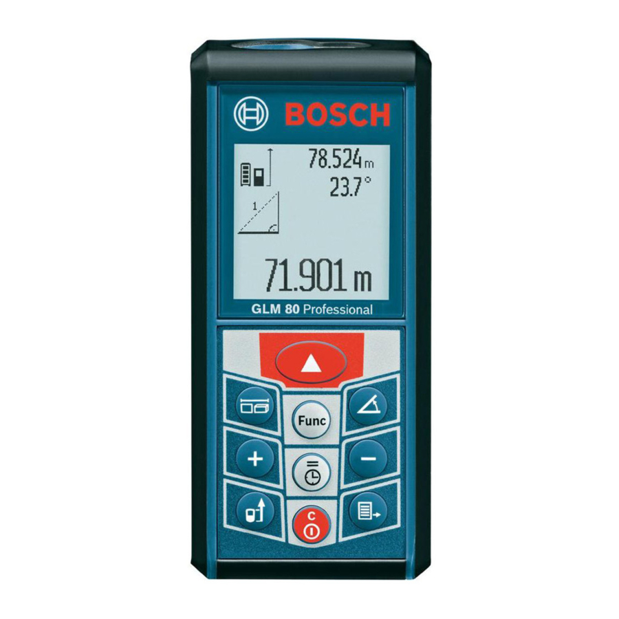
Functional Description
INTENDED USE
The measuring tool is intended for measuring distances, lengths, heights, clearances, grades and for the calculation of areas and volumes. The measuring tool is suitable for measuring indoors and outdoors.
PRODUCT FEATURES

- Display
- Measuring button
- Grade measurement/ calibration button
- Function mode/basic settings button
- Minus button
- Result/timer function
- Measured-value list/storage of constant button
- On/Off/clear button
- Positioning pin
- Reference level selection
- Plus button
- Length, area and volume measurement
- Charge socket cover
- Socket for charge connector
- Fixture for carrying strap
- Laser beam outlet
- Reception Lens
- Serial number label
- 1/4" threaded hole for mounting optional tripod
- Laser warning label
- Charge connector
- Battery charger
- Protective case
- Digital level attachment
- Locking lever for measuring rail
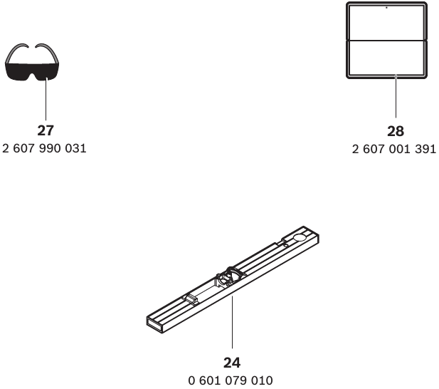
- Laser viewing glasses*
- Laser target plate*
*The accessories illustrated or described are not included.
**Keep button pressed to call up the extended functions.
DISPLAY ELEMENTS
- Measured-value lines
- "ERROR" indication
- Result line
- Digital vial/position of measured-value list entry
- Measured-value list indicator
- Measuring functions
 | Length measurement |
 | Area/surface measurement |
 | Volume measurement |
 | Continuous measurement |
 | Indirect height measurement |
 | Double indirect height measurement |
 | Indirect length measurement |
 | Timer function |
 | Wall-surface measurement |
 | Grade measurement |
Accessories
Technical Data


- The working range increases depending on how well the laser light is reflected from the surface of the target (scattered, not reflective) and with increased brightness of the laser point to the ambient light intensity (interior spaces, twilight). In unfavorable conditions (e.g. when measuring outdoors at intense sunlight), it may be necessary to use the target plate.
- For measurements from the rear measuring-tool edge. In unfavorable conditions (e.g. at intense sunlight or an insufficiently reflecting surface), the maximum deviation is ±10 mm per 80 m (±7/16 in per 265 ft). In favorable conditions, a deviation influence of ±0.05 mm/m (±1/64 in per 26 ft) must be taken into account.
- For measurements with the rear side of the unit as reference, the max. measuring range is ±60°.
- After calibration at 0° and 90° with an additional maximum pitch error of +/- 0,01°/° until 45°.
- In the continuous measurement function, the maximum operating temperature is 104°F (+40°C).
- at 77°F (25°C)
- For a new and charged battery without display illumination and tone signal.
Please observe the article number on the type plate of your battery charger. The trade names of the individual battery chargers may vary.
Please observe the article number on the type plate of your measuring tool. The trade names of the individual measuring tools may vary.
The measuring tool can be clearly identified with the serial number 18 on the type plate.
Preparation
Battery Charging
Do not use other battery chargers. The supplied battery charger is designed for the lithium-Ion battery in your machine.
Observe the outlet voltage! The voltage of the power source must correspond with the data on the type plate of the battery charger.
Note: The battery is supplied partially charged. To ensure full capacity of the battery, completely charge the battery in the battery charger before using your power tool for the first time.
The lithium-ion battery can be charged at any time without reducing its service life.
Interrupting the charging procedure does not damage the battery.
When the bottom segment of the battery charge control indicator g flashes, only a few more measurements can be carried out. Charge the battery.
The charge procedure begins as soon as the main plug of the battery charger is plugged into the socket outlet and the charge connector 21 is plugged into the socket 14.
The battery charge-control indicator g indicates the charging progress. During the charging procedure, the segments flash one after the other. When all segments of the battery charge-control indicator g are displayed, the battery is completely charged.
Disconnect the battery charger from the outlet when not using it for longer periods of time.
The measuring tool cannot be used during the charging procedure.

Protect the battery charger against moisture!
Recommendations for Optimal Handling of the Battery
Store the battery only within the allowable temperature range, see "Technical Data". As an example, do not leave the battery in a vehicle in the summer.
A significantly reduced working period after charging indicates that the battery is used and must be replaced.
Observe the notes for disposal.
IMPORTANT CHARGING NOTES
- The charger was designed to fast charge the battery only when Note: Use of chargers or battery the battery temperature is packs not sold by Bosch will void between 32 ̊F (0 ̊C ) and 113 ̊F (45 the warranty. ̊C ). If the battery pack is too hot or too cold, the charger will not fast charge the battery. (This may happen if the battery pack is hot from heavy use). When the battery temperature returns to between 32 ̊ F (0 ̊C ) and 113 ̊F (45 ̊C ), the charger will automatically begin charging.
- A substantial drop in operating time per charge may mean that the battery pack is nearing the end of its life and should be replaced.
- Remember to unplug charger during storage period.
- If battery does not charge properly:
- Check for voltage at outlet by plugging in some other electrical device.
- Check to see if outlet is connected to a light switch which turns power "off" when lights are turned off.
- Check battery pack terminals for dirt.
Clean with cotton swab and alcohol if necessary. - If you still do not get proper charging, take or send tool, battery pack and charger to your local Bosch Service Center. See "Tools, Electric" in the Yellow Pages for names and addresses.
Note: Use of chargers or battery packs not sold by Bosch will void the warranty.
Operation
INITIAL OPERATION
- Protect the measuring tool against moisture and direct sun irradiation.
- Do not expose the measuring tool to extreme temperatures or variations in temperature. As an example, do not leave it in vehicles for longer periods. In case of large variations in temperature, allow the measuring tool to adjust to the ambient temperature before putting it into operation. In case of extreme temperature or variations in temperature, the accuracy of the measuring tool can be impaired.
- Avoid heavy impact to or dropping the measuring tool. After severe exterior effects to the measuring tool, it is recommended to carry out an accuracy check (see "Accuracy Check and Calibration of the Grade Measurement" and "Accuracy Check of the Distance Measurement") each time before continuing work.
Switching On and Off
For switching on the measuring tool, the following possibilities are given:
- Pressing the On/Off button 8:
The measuring tool is switched on and in length measurement mode. The laser is not activated. - Pressing the measuring button 2: Measuring tool and laser are switched on. The measuring tool is in length measurement mode. When the measuring tool is inserted in the digital level attachment 24, the grade measurement function is activated.
To switch off the measuring tool, press the On/Off button 8 for a few seconds.
When no button on the measuring tool is pressed for approx. 5 minutes, the measuring tool automatically switches off to save the batteries.
When the angle is not changed for approx. 5 minutes when in the "Grade measurement" operating mode, the measuring tool automatically switches off to save batteries.
When switching off automatically, all stored values are retained.
Measuring Procedure
When the measuring tool is inserted in the digital level attachment 24, it is always in the length measurement or grade measurement function after switching on by pressing the measuring button 2. Other measuring modes can be switched by pressing the respective function/mode button (see "Measuring Functions")
After switching on, the rear edge of the measuring tool is preset as the reference level for the measurement. By pressing the reference level selection 10, the reference level can be changed (see "Selecting the reference level").
Place the measuring tool with the selected reference plane against the desired starting point of the measurement (e.g. a wall).
Briefly press the measuring button 2 to switch on the laser beam.
Aim the laser beam at the target surface. Push the measuring button 2 again to initiate the measurement.
When the laser beam is switched on permanently, the measurement already starts after the first actuation of the measuring button 2. In continuous measurement mode, the measurement starts immediately upon switching on.
Typically, the measured value appears after 0.5 and the latest after 4 seconds. The duration of the measurement depends on the distance, the light conditions and the reflection properties of the target surface. The end of the measurement is indicated by a signal tone. The laser beam is switched off automatically upon completion of the measurement.
When no measurement takes place approx. 20 seconds after collimating, the measuring tool automatically switches off to save the battery.
Selecting the Reference Level
For measuring, it is possible to select from four different reference points:

- The rear edge of the measuring tool or the front edge of the 90° folded-out positioning pin 9 (e.g when measuring onward from outer corners),
- The tip of the 180° folded out positioning pin 9 (e.g. when measuring from a corner),
- The front edge of the measuring tool (e.g., as when measuring from the edge of a table onward),
- The center of the 1/4" threaded hole 19 (e.g., for measuring with the tripod).
To select the reference level, press button 10 until the requested reference level is indicated on the display. Each time after switching on the measuring tool, the rear end of the measuring tool is preset as the reference level.
Subsequent changing of the reference level for measurements that have already been carried out (e.g. when indicated measuring values in the measured-value list) is not possible.
"Basic Settings" Menu
To access the "Basic Settings" menu, press and hold the basic settings button 4.
Briefly press the basic settings button 4 to select the individual menu items.
Press the minus button 5 or the plus button 11 to select the setting within the menu items.
To exit the "Basic settings" menu, press the measurement button 2.


With exception of the "Permanent laser beam"setting, all basic settings are retained when switching off.
Continuous Laser Beam
Do not point the laser beam at persons or animals and do not look into the laser beam yourself, not even from a large distance.
In this setting, the laser beam also remains switched on between measurements; for measuring, it is only required to press the measuring button 2 once.
Measuring Functions
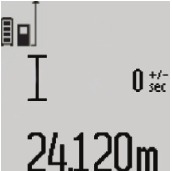
Simple Length Measurement
For length measurements, press button 12 until the "length measurement" ![]() indication appears on the display.
indication appears on the display.
To switch the laser on and for measuring, briefly press the measuring button 2 once each time.
The measured value is displayed in the result line c.
For several subsequent length measurements, the last measured results are displayed in the measured-value lines a.
Area Measurement
For area/surface measurements, press button 12 until the indicator for area measurement ![]() appears on the display.
appears on the display.
Afterwards, measure the length and the width, one after another, in the same manner as a length measurement. The laser beam remains switched on between both measurements.
Upon completion of the second measurement, the surface is automatically calculated and displayed in the result line c. The individual measured values are displayed in the measured-value lines a.
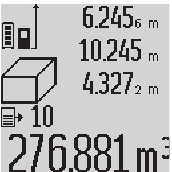
Volume Measurement
For volume measurements, press button 12 until the indicator for volume measurement  appears on the display.
Afterwards, measure the length, width and the height, one after another, in the same manner as for a length measurement. The laser beam remains switched on between all three measurements.
Upon completion of the third measurement, the volume is automatically calculated and displayed in the result line c. The individual measured values are displayed in the measured-value lines a.
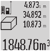
Values above 999999 m3 cannot be indicated; "ERROR" appears on the display. Divide the volume to be measured into individual measurements; their values can then be calculated separately and then summarized.
Continuous Measurement (Tracking)/Minimum/Maximum Measurement

For continuous measurements, the measuring tool can be moved relative to the target, whereby the measuring value is updated approx. every 0.5 seconds. In this manner, as an example, you can move a certain distance away from a wall, while the actual distance can always be read.
For continuous measurements, press function mode button 4 until the indicator for continuous measurement  appears on the display. To start the continuous measurement, press the measuring button 2.
The minimum measurement is used to determine the shortest distance from a fixed reference point. It is used, as an example, for determining plumb lines or horizontal partitions.
The maximum measurement is used to determine the greatest distance from a fixed reference point. It is used, as an example, for determining diagonals.
The current measuring value is displayed in the result line c. The maximal ("max") and the minimal ("min") measuring value are displayed in the measured value lines a.
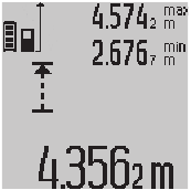
It is always overwritten, when the current length measurement value is less than the present minimal or larger than the present maximal value.
The previous minimal and maximal values are deleted by pressing the button for clearing the internal memory 8.
Pressing the measuring button 2 ends the continuous measurement. The last measured value is displayed in the result line c.
Pressing the measuring button 2 again restarts a continuous measuring run.
Continuous measurement automatically switches off after 5 min. The last measured value remains indicated in the result line c.
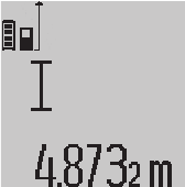
Indirect Distance Measurement
The indirect distance measurement is used to measure distances that cannot be measured directly because an obstacle would obstruct the laser beam or no target surface is available as a reflector. This measuring procedure can only be used in vertical direction. Any deviation in horizontal direction leads to measuring errors.
The laser beam remains switched on between the individual measurements.
For indirect length measurements, three measuring modes are available. Each measuring mode can be used for determining different distances.
- Indirect height measurement

Press the function-mode button 4 until the indication for indirect height measurement![]() appears on the display.
appears on the display.
Pay attention that the measuring tool is positioned at the same height as the bottom measuring point. Now, tilt the measuring tool around the reference plane and measure distance "1" as for a length measurement.
Upon completion of the measurement, the result for the sought distance "X" is displayed in the result line c. The measuring values for the distance "1" and the angle "α"are displayed in the measured-value lines a.
![]()
- Double indirect height measurement

Press the function-mode button 4 until the indication for double indirect height measurement![]() appears on the display.
appears on the display.
Measure distances "1" and "2" in this sequence as for a length measurement.
Upon completion of the measurement, the result for the sought distance "X" is displayed in the result line c. The measuring values for the distances "1", "2" and the angle "α" are displayed in the measured-value lines a.
![]()
Pay attention that the reference plane of the measurement (e.g. the rear edge of the measuring tool) remains exactly at the same location for all individual measurements within a measuring sequence. - Indirect length measurement

Press the function-mode button 4 until the indication for indirect length measurement![]() appears on the display.
appears on the display.
Pay attention that the measuring tool is positioned at the same height as the sought measuring point. Now, tilt the measuring tool around the reference plane and measure distance "1" as for a length measurement.
Upon completion of the measurement, the result for the sought distance "X" is displayed in the result line c. The measuring values for the distance "1" and the angle "α"are displayed in the measured-value lines a.
![]()

 appears on the display.
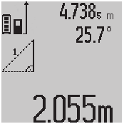

 appears on the display.
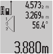

 appears on the display.
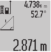
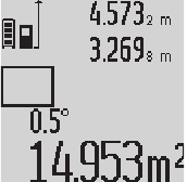
Wall Surface Measurement

The wall surface measurement is used to determine the sum of several individual surfaces with a common height.
In the example shown, the total surface of several walls that have the same room height A, but different lengths B, are to be determined.
For wall surface measurements, press the function-mode button 4 until the indicator for wall surface measurement  appears on the display.
Measure the room height A as for a length measurement. The measured value ("cst") is displayed in the top measured value line a. The laser remains switched on.
Afterwards, measure length B1 of the first wall. The surface is automatically calculated and displayed in the result line c. The length measurement value is displayed in the center measured value line a. The laser remains switched on.
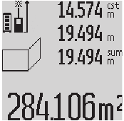
Now, measure length B2 of the second wall.
The individually measured value displayed in the center measured value line a is added to the length B1. The sum of both lengths ("sum", displayed in the bottom measured-value line a) is multiplied with the stored height A. The total surface value is displayed in the result line c.
In this manner, you can measure any number of further lengths BX, which are automatically added and multiplied with height A.
The condition for a correct area/surface calculation is that the first measured length (in the example the room height A) is identical for all partial surfaces.
Grade measurement

After pressing the grade measurement button 3, the indication for grade measurement appears on the display  . The backside of the measuring tool is used as the reference plane. By pressing the grade measurement button 3 again, the side surfaces of the measuring tool are used as reference plane and the display view is shown turned by 90°.
Press the measuring button 2 to lock the measuring value and accept it in the measured values memory. Pressing the measuring button 2 again continues the measurement.
When the indication flashes during the measuring procedure, then the measuring tool was tilted too much in lateral direction.
If the "digital vial " function is activated in the basic settings, the grade value is also displayed in the other measuring functions in line d of display 1.
Timer function
The timer function is helpful, when, for example, movements of the measuring tool during measuring are to be prevented.
To activate the timer function, press and hold button 6 until the indicator appears in the display.
The time period from the actuation until the measurement takes place is displayed in the measured-value line a. The time period can be adjusted between 1 s and 60 s by pressing the plus button 11 or the minus button 5.
The measurement takes place automatically after the set time period has elapsed.
The timer function can also be used for distance measurements within other measuring modes (e.g. area/surface measurement). Adding and subtracting measuring results as well as continuous measurements are not possible.
List of the last Measuring Values
The measuring tool stores the last 20 measuring values and their calculations, and displays them in reverse order (last measured value first).
To recall the stored measurements, press button 7. The result of the last measurement is indicated on the display, along with the indicator for the measured value list e and the memory location of the displayed measurements.
When no further measurements are stored after pressing button 7 again, the measuring tool switches back to the last measuring function. To exit the measured-value list, press one of the measuring-mode buttons.
To continuously save the currently displayed length measurement value as a constant, press and hold the measured-value list button 7 until "CST" is indicated on the display. A measured value list entry cannot be subsequently saved as a constant.
To use a length measurement value in a measuring mode (e. g. area/surface measurement), press the measured-value list button 7, select the desired entry and confirm by pressing the result button 6.
Deleting Measured Values
Briefly pressing button 8 deletes the last individual measuring value determined in all measuring functions. Briefly pressing the button repeatedly deletes the individual measured values in reverse order.
To delete the currently displayed measured value list entry, briefly press button 8.
To delete the complete measured value list and the constant "CST", press and hold the measured-value list button 7 and at the same time briefly press button 8.
In wall surface measurement mode, briefly pressing button 8 the first time deletes the last individually measured value; pressing the button a second time deletes all lengths BX, and pressing the button a third time deletes all room heights A.
Adding Measured Values
To add measured values, firstly carry out any measurement or select an entry from the measured value list. Then press the plus button 11. For confirmation, "+" appears on the display. Then carry out a second measurement or select another entry from the measured-value list.
To call up the sum of both measurements, press the result button 6. The calculation is indicated in the measured-value lines a, and the sum in the result line c.
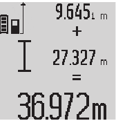
After calculation of the sum, further measured values or measured-value list entries can be added to this result when pressing the plus button 11 prior to each measurement. Pressing the result button 6 ends the addition.
Notes:
- Mixed length, area and volume values cannot be added together. For example, when a length and area value are added, "ERROR" briefly appears on the display after pressing the result button 6. Afterwards, the measuring tool switches back to the last active measuring mode.
- For each calculation, the result of one measurement is added (e.g. the volume value); for continuous measurements, this would be the displayed measured value in result line c. The addition of individual measured values from the measured-value lines a is not possible.
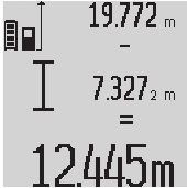
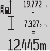
Subtracting Measured Values
To subtract measuring values, press minus button 5; For confirmation, "–" is indicated on the display. The further procedure is analog to "Adding Measured Values".
Working Advice
General Information
The reception lens 17 and the laser beam outlet 16 must not be covered when taking a measurement.
The measuring tool must not be moved while taking a measurement (with the exception of the continuous measurement and grade measurement functions). Therefore, place the measuring tool, as far as this is possible, against or on a firm stop or supporting surface.
Influence Effects on the Measuring Range
The measuring range depends upon the light conditions and the reflection properties of the target surface. For improved visibility of the laser beam when working outdoors and when the sunlight is intense, use the laser viewing glasses 26 (accessory) and the laser target plate 27 (accessory), or shade off the target surface.
Influence Effects on the Measuring Result
Due to physical effects, faulty measurements cannot be excluded when measuring on different surfaces. Included here are:
- Transparent surfaces (e.g., glass, water),
- Reflecting surfaces (e.g., polished metal, glass),
- Porous surfaces (e.g. insulation materials),
- Structured surfaces (e.g., roughcast, natural stone).
If required, use the laser target plate 27 (accessory) on these surfaces.
Furthermore, faulty measurements are also possible when sighting inclined target surfaces.
Also, air layers with varying temperatures or indirectly received reflections can affect the measured value.
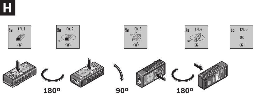
Accuracy Check and Calibration of the Grade Measurement
Regularly check the accuracy of the grade measurement. This is done by carrying out a reversal measurement. For this, place the measuring tool on a table and measure the grade. Turn the measuring tool by 180° and measure the grade again. The difference of the indicated reading may not exceed by more than 0,3° (max.).
In case of greater deviation, the measuring tool must be recalibrated. For this, press and hold the grade measurement button 3. Follow the directions on the display.
Accuracy Check of the Distance Measurement
The accuracy of the distance measurement can be checked as follows:
- Select a permanently unchangeable measuring section with a length of approx. 1 to 10 meters; its length must be precisely known (e.g. the width of a room or a door opening). The measuring distance must be indoors; the target surface for the measurement must be smooth and reflect well.
- Measure the distance 10 times after another.
The deviation of the individual measurements from the mean value must not exceed ±2 mm (max.). Log the measurements, so that you can compare their accuracy at a later point of time.
Working with a Tripod
The use of a tripod is particularly necessary for larger distances. Position the measuring tool with the 1/4" thread 19 onto the quick-change plate of the tripod or a commercially available camera tripod. Tighten the measuring tool with the locking screw of the quick-change plate.
Set the corresponding reference level for measurement with a tripod by pushing button 10 (the reference level is the thread).
Working with the digital level attachment
The digital level attachment 24 can be used for a more accurate grade measurement result. Distance measurements are not possible with the digital level attachment.


Place the measuring tool into the digital level attachment 24 as shown and lock the measuring tool with locking lever 25. Press the measuring button 2 to activate the "digital level attachment" operating mode.
Regularly check the accuracy of the grade measurement by carrying out a reversal measurement or with the spirit levels of the digital level attachment.
In case of greater deviation, the measuring tool must be recalibrated. For this, press and hold the grade measurement button 3. Follow the directions on the display.
To end the "digital level attachment" operating mode, switch the measuring tool off and remove it from the digital level attachment.
Troubleshooting – Causes and Corrective Measures
| Cause | Corrective Measure |
| Temperature warning indicator (k) flashing; measurement not possible | |
| The measuring tool is outside the operating temperature range from 14°F to 122°F (in the function continuous measurement up to 104°F). | Wait until the measuring tool has reached the operating temperature |
| "ERROR" indication in the display | |
| Addition/Subtraction of measured values with different units of measure | Only add/subtract measured values with the same units of measure |
| The angle between the laser beam and the target is too acute. | Enlargen the angle between the laser beam and the target |
| The target surface reflects too intensely (e.g. a mirror) or insufficiently (e.g. black fabric), or the ambient light is too bright. | Work with the laser target plate 28 (accessory) |
| The laser beam outlet 16 or the reception lens 17 are misted up (e.g. due to a rapid temperature change). | Wipe the laser beam outlet 16 and/or the reception lens 17 dry using a soft cloth |
| Calculated value is greater than 999999 m/m2/m3. | Divide calculation into intermediate steps |
| Indication ">60°" or "<-60°" on the display | |
| The inclination measuring range for the measuring mode and/or the reference plane has been exceeded. | Carry out the measurement within the specified angle range. |
| "CAL and "ERROR" indication in the display | |
| The calibration of the grade measurement was not carried out in the correct sequence or in the correct positions. | Repeat the calibration according to the instructions on the display and in the operating instructions. |
| The surfaces used for the calibration were not accurately aligned (horizontal or vertical). | Repeat the calibration on a horizontal or vertical surface; if required, check the surface first with a level. |
| The measuring tool was moved or tilted while pressing the button. | Repeat the calibration and hold the measuring tool in place while pressing the button. |
| Battery charge-control indicator (g), temperature warning (k) and "ERROR" indication in the display | |
| Temperature of the measuring tool not within the allowable charge-temperature range | Wait until the charge-temperature range is reached. |
| Battery charge-control indicator (g) and "ERROR" indication in the display | |
| Battery charging voltage not correct | Check if the plug-in connection has been established correctly and if the battery charger is operating properly. When the unit symbol is flashing, the battery is defective and must be re-placed by a Bosch after-sales service. |
| Battery charge-control indicator (g) and clock symbol f in the display | |
| Measuring result not plausible | |
| The target surface does not reflect correctly (e.g. water, glass). | Cover off the target surface |
| The laser beam outlet 16 or the reception lens 17 are covered. | Make sure that the laser beam outlet 16 or the reception lens 17 are unobstructed |
| Wrong reference level set | Select reference level that corresponds to measurement |
| Obstruction in path of laser beam | Laser point must be completely on target surface. |
| The indication remains unchanged or the measuring tool reacts unexpected after pressing a button | |
| Software error | Press the measuring button 2 and the button for clearing the internal memory/On/Off 8 to reset the software. |
The measuring tool monitors the correct function for each measurement. When a defect is determined, only the symbol shown aside flashes in the display. In this case, or when the above mentioned corrective measures cannot correct an error, have the measuring tool checked by an after-sales service agent for Bosch power tools. | |
Maintenance and Service
Store and transport the measuring tool only in the supplied protective case.
Keep the measuring tool clean at all times.
Do not immerse the measuring tool into water or other fluids.
Wipe off debris using a moist and soft cloth. Do not use any cleaning agents or solvents.
Maintain the reception lens 17 in particular, with the same care as required for eye glasses or the lens of a camera.
The battery is not serviceable and should be repaired by an authorized service center.
If the measuring tool should fail despite the care taken in manufacturing and testing procedures, repair should be carried out by an authorized after-sales service center for Bosch power tools. Do not open the measuring tool yourself.
In all correspondence and spare parts orders, please always include the 10-digit article number given on the type plate of the measuring tool.
In case of repairs, send in the measuring tool packed in its protective case 23.
General Safety Rules
LASER RADIATION. AVOID DIRECT EYE EXPOSURE. DO NOT stare into the laser light source. Never aim light at another person or object other than the workpiece. Laser light can damage your eyes.
Read all instructions. Failure to follow all instructions listed below may result in electric shock, fire and/or serious injury.

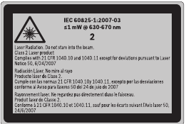
Do not direct the laser beam at persons or animals and do not stare into the laser beam yourself. This tool produces laser class 2 laser radiation and complies with 21 CFR 1040.10 and 1040.11 except for deviations pursuant to Laser Notice No. 50, dated June 24, 2007. This can lead to persons being blinded.
Safety Rules
Working safely with the measuring tool is possible only when the operating and safety information are read completely and the instructions contained therin are strictly followed. Never make warning labels on the Measuring tool unrecognizable.
Never aim the beam at a workpiece with a reflective surface. Bright shiny reflective sheet steel or similar reflective surfaces are not recommended for laser use. Reflective surfaces could direct the beam back toward the operator.
Take care to recognize the accuracy and range of the device. Measurement may not be accurate if used beyond the rated range of the device.
Use of controls or adjustments or performance of procedures other than those specified herein may result in hazardous radiation exposure.
The use of optical instruments with this product will increase eye hazards.
Have the measuring tool repaired only through qualified specialist using original spare parts. This ensures that the safety of the measuring tool is maintained.
Do not allow children to use the measuring tool without supervision. They could unintentionally blind other persons.
Do not point the laser beam at persons or animals and do not look into the laser beam yourself, not even from a large distance. Do not use the laser viewing glasses as safety goggles. The laser viewing glasses are used for improved visualization of the laser beam, but they do not protect against laser radiation.
Do not use the laser viewing glasses as sun glasses or in traffic. The laser viewing glasses do not afford complete UV protection and reduce color perception.
Safe Operating Procedures

Be sure to read and understand all instructions in this manual before using this product. Failure to follow all instructions may result in hazardous radiation exposure, electric shock, fire, and/or bodily injury.

Use of controls or adjustments or performance of procedures other than those specified in this manual, may result in hazardous radiation exposure.
The use of optical instruments with this product will increase eye hazard.
The following labels are on your measuring tool for your convenience and safety. They indicate where the laser light is emitted by the level. ALWAYS BE AWARE of their location when using the level.
ALWAYS: Make sure that any bystanders in the vicinity of use are made aware of the dangers of looking directly into the measuring tool.
DO NOT remove or deface any warning or caution labels.
Removing labels increases the risk of exposure to laser radiation.
DO NOT stare directly at the laser beam or project the laser beam directly into the eyes of others. Serious eye injury could result.
DO NOT place the measuring tool in a position that may cause anyone to stare into the laser beam intentionally or unintentionally. Serous eye injury could result.
DO NOT use any optical tools such as, but not limited to, telescopes or transits to view the laser beam. Serious eye injury could result.
DO NOT operate the measuring tool around children or allow children to operate the measuring tool. Serious eye injury could result.
ALWAYS turn the measuring tool "OFF" when not in use. Leaving the measuring tool "ON" increases the risk of someone inadvertently staring into the laser beam.
DO NOT operate the measuring tool in combustible areas such as in the presence of flammable liquids, gases or dust.
ALWAYS position the measuring tool securely. Damage to the measuring tool and/or serious injury to the user could result if the measuring tool falls.
ALWAYS use only the accessories that are recommended by the manufacturer of your measuring tool. Use of accessories that have been designed for use with other measuring tools could result in serious injury.
DO NOT leave measuring tool "on" unattended in any operation mode.
ALWAYS repair and servicing must be performed by a qualified repair facility. Repairs performed by unqualified personnel could result in serious injury.
DO NOT use this measuring tool for any purpose other than those outlined in this manual. This could result in serious injury.
DO NOT disassemble the measuring tool. There are no user serviceable parts inside. Disassembling the laser will void all warranties on the product. Do not modify the product in any way. Modifying the measuring tool may result in hazardous laser radiation exposure.
In case of damage and improper use of the battery, vapors may be emitted. Provide for fresh air and seek medical help in case of complaints. The vapors can irritate the respiratory system.
Electrical Safety Procedures
Batteries can explode or leak, and can cause injury or fire. To reduce this risk:
ALWAYS follow all instructions and warnings on the battery label and package.
DO NOT short any battery terminals.
DO NOT dispose of batteries in fire.
KEEP batteries out of reach of children.
Safety Warnings for Battery Chargers
Keep the battery charger away from rain or moisture. Penetration of water in the battery charger increases the risk of an electric shock.
Do not charge other batteries. The battery charger is suitable only for charging Bosch lithium ion batteries within the listed voltage range. Otherwise there is danger of fire and explosion.
Keep the battery charger clean. Contamination can lead to danger of electric shock.
Before each use, check the battery charger, cable and plug.
If damage is detected, do not use the battery charger. Never open the battery charger yourself. Have repairs performed only by a qualified technician and only using original spare parts. Damaged battery chargers, cables and plugs increase the risk of an electric shock.
Do not operate the battery charger on easily inflammable surfaces (e.g., paper, textiles, etc.) or surroundings. The heating of the battery charger during the charging process can pose a fire hazard.
Before using battery charger, read all instructions and cautionary markings on
- battery charger,
- battery pack, and
- product using battery.
Use only the charger which accompanied your product or direct replacement as listed in the catalog or this manual. Do not substitute any other charger. Use only Bosch approved chargers with your product. See Functional Description and Specifications.
Do not disassemble charger or operate the charger if it has received a sharp blow, been dropped or otherwise damaged in anyway. Replace damaged cord or plugs immediately. Incorrect reassembly or damage may result in electric shock or fire.
Do not recharge battery in damp or wet environment. Do not expose charger to rain or snow. If battery case is cracked or otherwise damaged, do not insert into charger. Battery short or fire may result.
Charge only Bosch approved rechargeable batteries. See Functional Description and Specifications. Other types of batteries may burst causing personal injury and damage.
Charge battery pack in temperatures above +32 degrees F (0 degrees C) and below +113 degrees F (45 degrees C). Store tool and battery pack in locations where temperatures will not exceed 120 degrees F (49 degrees C). This is important to prevent serious damage to the battery cells.
Battery leakage may occur under extreme usage or temperature conditions. Avoid contact with skin and eyes. The battery liquid is caustic and could cause chemical burns to tissues. If liquid comes in contact with skin, wash quickly with soap and water. If the liquid contacts your eyes, flush them with water for a minimum of 10 minutes and seek medical attention.
Place charger on flat nonflammable surfaces and away from flammable materials when re-charging battery pack. The charger and battery pack heat during charging. Carpeting and other heat insulating surfaces block proper air circulation which may cause overheating of the charger and battery pack. If smoke or melting of the case are observed unplug the charger immediately and do not use the battery pack or charger.
Use of an attachment not recommended or sold by Bosch may result in a risk of fire, electric shock or injury to persons.
Battery Care
When batteries are not in tool or charger, keep them away from metal objects. For example, to protect terminals from shorting DO NOT place batteries in a tool box or pocket with nails, screws, keys, etc. Fire or injury may result.
DO NOT PUT BATTERIES INTO FIRE OR EXPOSE TO HIGH HEAT. They may explode.
Call Toll Free for Consumer Information & Service Locations
1-877-BOSCH99 (1-877-267-2499)
www.boschtools.com
Documents / Resources
References

Download manual
Here you can download full pdf version of manual, it may contain additional safety instructions, warranty information, FCC rules, etc.
Advertisement


Need help?
Do you have a question about the GLM80 and is the answer not in the manual?
Questions and answers