Bosch UniversalLevel 360 Manual
- Original instructions manual (246 pages)
Advertisement
Product Description and Specifications
Please observe the illustrations at the beginning of this operating manual.
Intended Use
The measuring tool is intended for determining and checking horizontal and vertical lines.
The measuring tool is suitable for indoor use.
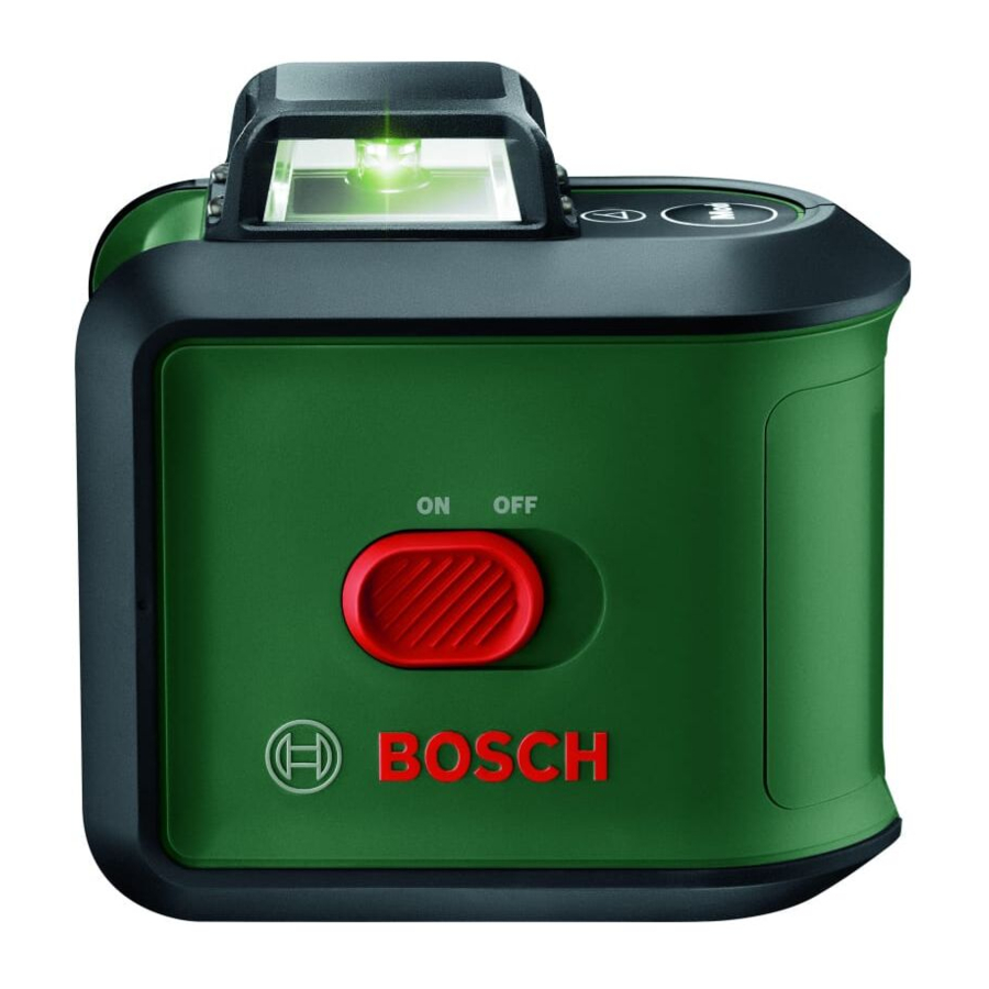
Product Features
The numbering of the product features shown refers to the illustration of the measuring tool on the graphic page.


- Button for laser operating mode
- Incline function button
- Status indicator
- On/off switch
- Laser beam outlet aperture
- Laser warning label
- Serial number
- 1/4" tripod mount
- Battery compartment cover locking mechanism
- Battery compartment cover
- TripodA)
- Laser gogglesA)
- Telescopic rodA)
A)Accessories shown or described are not included with the product as standard. You can find the complete selection of accessories in our accessories range.
Technical Data
| Cross line laser | UniversalLevel 360 |
| Article number | 3 603 F63 E.. |
| Working range (diameter) up to approx.A) | 24 m |
| Aperture angle for vertical laser line | 120° |
| Levelling accuracy B)C)D) | ±0.4 mm/m |
| Self-levelling range | ±4° |
| Levelling time | ≤ 4 s |
| Operating temperature | –5°C to +40°C |
| Storage temperature | –20°C to +70°C |
| Max. altitude | 2000 m |
| Relative air humidity max. | 90 % |
| Pollution degree according to IEC 61010-1 | 2E) |
| Laser class | 2 |
| Laser type | 500–540 nm, < 10 mW |
| Colour of the laser beam | Green |
| C 6 | 10 |
| Divergence | 30 × 20 mrad (full angle) |
| Tripod mount | 1/4" |
| Batteries | 4 × 1.5 V LR6 (AA) |
| Operating duration (for cross-line mode) at least | 4 h |
| Weight according to EPTA-Procedure 01:2014 | 0.56 kg |
| Dimensions (length × width × height) | 114 × 66 × 111 mm |
A) The working range may be reduced by unfavourable environmental conditions (e.g. direct sunlight).
B) Applies for the intersection point and the corresponding angles 90°/180°/270°
C) At 20–25 °C
D) The values stated presuppose normal to favourable environmental conditions (e.g. no vibration, no fog, no smoke, no direct sunlight). Extreme fluctuations in temperature can cause deviations in accuracy.
E) Only non-conductive deposits occur, whereby occasional temporary conductivity caused by condensation is expected.
The serial number (7) on the type plate is used to clearly identify your measuring tool.
Assembly
Inserting/changing the batteries
It is recommended that you use alkaline manganese batteries to operate the measuring tool.
To open the battery compartment cover (10), press on the locking mechanism (9) and remove the battery compartment cover. Insert the batteries.
When inserting the batteries, ensure that the polarity is correct according to the illustration on the inside of the battery compartment.
If the batteries are drained, the status display (3) will light up red and the laser beams will be switched off. Switch off the measuring tool and replace the batteries.
Always replace all the batteries at the same time. Only use batteries from the same manufacturer and which have the same capacity.
- Take the batteries out of the measuring tool when you are not using it for a prolonged period of time. The batteries can corrode and self-discharge during prolonged storage in the measuring tool.
Operation
Starting Operation
- Protect the measuring tool from moisture and direct sunlight.
- Do not expose the measuring tool to any extreme temperatures or variations in temperature. For example, do not leave it in a car for extended periods of time. In case of large variations in temperature, allow the measuring tool to adjust to the ambient temperature before putting it into operation. The precision of the measuring tool may be compromised if exposed to extreme temperatures or variations in temperature.
- Avoid substantial knocks to the measuring tool and avoid dropping it. Damaging the measuring tool can cause accuracy to be compromised. If the laser line is subjected to a substantial knock or is dropped, check it by comparing it to a known horizontal or vertical reference line.
- Switch the measuring tool off when transporting it. The pendulum unit is locked when the tool is switched off, as it can otherwise be damaged by big movements.
Switching On/Off
To switch on the measuring tool, slide the on/off switch (4) to the "ON" position. As soon as it is switched on, the measuring tool emits laser lines from the outlet apertures (5).
- Do not direct the laser beam at persons or animals and do not stare into the laser beam yourself (even from a distance).
To switch off the measuring tool, slide the on/off switch (4) to the OFF position. The pendulum unit is locked when the tool is switched off. - Never leave the measuring tool unattended when switched on, and ensure the measuring tool is switched off after use. Others may be blinded by the laser beam.
Operating Modes
The measuring tool has several operating modes, which you can switch between at any time:
- Cross-line operation (see figure A): The measuring tool generates a horizontal laser plane (360° circumferential laser line) and a vertical laser line pointing forwards

- Horizontal mode (see figure B): Generates a horizontal laser plane (360° circumferential laser line)

- Vertical mode (see figure C): Generates one vertical laser line


Once the measuring tool has been switched on, it is in cross-line operation with automatic levelling. To change the operating mode, press the laser mode button Mode (1).
All operating modes can be used with both automatic levelling and the incline function.
Automatic Levelling
Working with automatic levelling (see figure E)
To work with automatic levelling, the automatic levelling status indicator (3) must not light up continuously. If necessary, switch automatic levelling on again by pressing the incline function button (2) so that the status indicator goes out.
Position the measuring tool on a level, firm surface or attach it to the tripod (11), or the telescopic shaft (13).
The automatic levelling function automatically compensates irregularities within the selflevelling range of ±4°. The levelling is finished as soon as the laser lines stop moving.
If automatic levelling is not possible, e.g. because the surface on which the measuring tool stands deviates by more than 4° from the horizontal plane, the laser beams begin to flash.
If this is the case, set up the measuring tool in a level position and wait for the self-levelling to take place. As soon as the measuring tool is within the self-levelling range of ±4°, the laser beams will light up continuously.
It is not possible to work with automatic levelling outside the self-levelling range of ±4°, as the levelling accuracy of the laser beams cannot be guaranteed and it cannot be guaranteed that the laser beams are perpendicular.
In case of ground vibrations or position changes during operation, the measuring tool is automatically levelled again. Upon re-levelling, check the position of the horizontal or vertical laser line with regard to the reference points to avoid errors by moving the measuring tool.

Working with the incline function (see figure F)
To work with the tilt function, press the incline function button (2). When the incline function is engaged, the status indicator (3) lights up green.
For work with the incline function, automatic levelling is switched off. You can hold the measuring tool freely in your hand or place it on a sloping surface. This means that the laser beams are no longer levelled and no longer necessarily run perpendicular to one another.

Working Advice
- Only the centre of the laser line must be used for marking. The width of the laser line changes depending on the distance.
Working with the Tripod (Accessory)
A tripod offers a stable, height-adjustable support surface for measuring. Place the measuring tool with the 1/4" tripod mount (8) on the thread of the tripod (11) or a conventional camera tripod. Tighten the measuring tool using the locking screw of the tripod.
Roughly align the tripod before switching on the measuring tool.
Laser Goggles (Accessory)
The laser goggles filter out ambient light. This makes the light of the laser appear brighter to the eye.
- Do not use the laser goggles as protective goggles. The laser goggles make the laser beam easier to see; they do not protect you against laser radiation.
- Do not use the laser goggles as sunglasses or while driving. The laser goggles do not provide full UV protection and impair your ability to see colours.
Example applications (see figures E–F)
Examples of possible applications for the measuring tool can be found on the graphics pages.

Maintenance and Service
Maintenance and Cleaning
Keep the measuring tool clean at all times.
Never immerse the measuring tool in water or other liquids.
Wipe off any dirt using a damp, soft cloth. Do not use any detergents or solvents.
The areas around the outlet aperture of the laser in particular should be cleaned on a regular basis. Make sure to check for lint when doing this.
After-Sales Service and Application Service
Our after-sales service responds to your questions concerning maintenance and repair of your product as well as spare parts. You can find explosion drawings and information on spare parts at: www.bosch-pt.com
The Bosch product use advice team will be happy to help you with any questions about our products and their accessories.
In all correspondence and spare parts orders, please always include the 10‑digit article number given on the nameplate of the product.
Great Britain
Robert Bosch Ltd. (B.S.C.)
P.O. Box 98
Broadwater Park
North Orbital Road
Denham Uxbridge
UB 9 5HJ
At www.bosch-pt.co.uk you can order spare parts or arrange the collection of a product in need of servicing or repair.
Tel. Service: (0344) 7360109
E-Mail: boschservicecentre@bosch.com
Ireland
Origo Ltd.
Unit 23 Magna Drive
Magna Business Park
City West
Dublin 24
Tel. Service: (01) 4666700
Fax: (01) 4666888
Australia, New Zealand and Pacific Islands
Robert Bosch Australia Pty. Ltd.
Power Tools
Locked Bag 66
Clayton South VIC 3169 Customer Contact Center Inside Australia:
Phone: (01300) 307044 Fax: (01300) 307045
Inside New Zealand:
Phone: (0800) 543353 Fax: (0800) 428570
Outside AU and NZ:
Phone: +61 3 95415555
www.bosch-pt.com.au
www.bosch-pt.co.nz
Republic of South Africa
Customer service
Hotline: (011) 6519600
Gauteng – BSC Service Centre
35 Roper Street, New Centre
Johannesburg
Tel.: (011) 4939375
Fax: (011) 4930126
E-Mail: bsctools@icon.co.za
KZN – BSC Service Centre
Unit E, Almar Centre
143 Crompton Street
Pinetown
Tel.: (031) 7012120
Fax: (031) 7012446
E-Mail: bsc.dur@za.bosch.com
Western Cape – BSC Service Centre
Democracy Way, Prosperity Park
Milnerton
Tel.: (021) 5512577
Fax: (021) 5513223
E-Mail: bsc@zsd.co.za
Bosch Headquarters
Midrand, Gauteng
Tel.: (011) 6519600
Fax: (011) 6519880
E-Mail: rbsa-hq.pts@za.bosch.com
Robert Bosch Power Tools GmbH
70538 Stuttgart
GERMANY
www.bosch-pt.com
Safety Instructions

All instructions must be read and observed in order for the measuring tool to function safely. The safeguards integrated into the measuring tool may be compromised if the measuring tool is not used in accordance with these instructions. Never make warning signs on the measuring tool unrecognisable. SAVE THESE INSTRUCTIONS FOR FUTURE REFERENCE AND INCLUDE THEM WITH THE MEASURING TOOL WHEN TRANSFERRING IT TO A THIRD PARTY.
![]()
If operating or adjustment devices other than those specified here are used or other procedures are carried out, this can lead to dangerous exposure to radiation.- The measuring tool is delivered with a laser warning sign (marked in the illustration of the measuring tool on the graphics page).
- If the text of the laser warning label is not in your national language, stick the provided warning label in your national language over it before operating for the first time.
![]()
Do not direct the laser beam at persons or animals and do not stare into the direct or reflected laser beam yourself. You could blind somebody, cause accidents or damage your eyes. - If laser radiation hits your eye, you must close your eyes and immediately turn your head away from the beam.
- Do not make any modifications to the laser equipment.
- Do not use the laser goggles as protective goggles. The laser goggles make the laser beam easier to see; they do not protect you against laser radiation.
- Do not use the laser goggles as sunglasses or while driving. The laser goggles do not provide full UV protection and impair your ability to see colours.
- Have the measuring tool serviced only by a qualified specialist using only original replacement parts. This will ensure that the safety of the measuring tool is maintained.
- Do not let children use the laser measuring tool unsupervised. They could accidentally dazzle someone.
- Do not use the measuring tool in explosive atmospheres which contain flammable liquids, gases or dust. Sparks may be produced inside the measuring tool, which can ignite dust or fumes.


Documents / Resources
References
![www.bosch-pt.com]() Home | Bosch Power Tools
Home | Bosch Power Tools![www.bosch-pt.co.uk]() Home | Bosch Power Tools
Home | Bosch Power ToolsBosch power tools for trade and industry | Bosch Professional
Bosch power tools for trade and industry | Bosch Professional
Download manual
Here you can download full pdf version of manual, it may contain additional safety instructions, warranty information, FCC rules, etc.
Advertisement


Need help?
Do you have a question about the UniversalLevel 360 and is the answer not in the manual?
Questions and answers