Table of Contents
Advertisement
Quick Links
Download this manual
See also:
Owner's Manual
Owner's Manual
Thank you, and congratulations on your choice of the
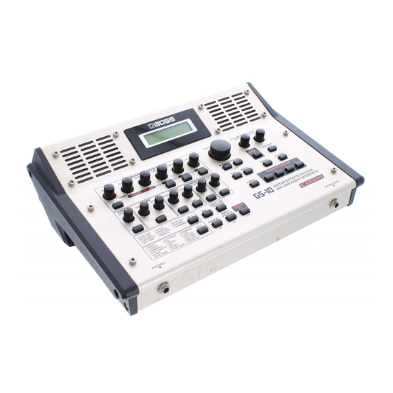
BOSS GS-10 Guitar Effects System with USB Audio Interface.
Before using this unit, carefully read the sections entitled:
• USING THE UNIT SAFELY (page 2–3)
• IMPORTANT NOTES (page 4–5)
These sections provide important information concerning the
proper operation of the unit.
Additionally, in order to feel assured that you have gained a
good grasp of every feature provided by your new unit, Owner's
manual should be read in its entirety. The manual should be
saved and kept on hand as a convenient reference.
■ Printing Conventions in This Manual
• Text or numerals enclosed in square brackets [ ] indicate buttons.
[WRITE]
WRITE button
[USB]
USB button
• Reference such as (p. **) indicate pages in this manual to which you
can refer.
Copyright © 2003 BOSS CORPORATION
All rights reserved. No part of this publication may be reproduced in any form
without the written permission of BOSS CORPORATION.
Advertisement
Table of Contents

Related Manuals for Boss GS-10


Summary of Contents for Boss GS-10
- Page 1 Owner’s Manual Thank you, and congratulations on your choice of the BOSS GS-10 Guitar Effects System with USB Audio Interface. Before using this unit, carefully read the sections entitled: • USING THE UNIT SAFELY (page 2–3) • IMPORTANT NOTES (page 4–5) These sections provide important information concerning the proper operation of the unit.
-
Page 2: Using The Unit Safely
Refer a long period of time at a high volume level, or at all servicing to your retailer, the nearest Roland a level that is uncomfortable. If you experience Service Center, or an authorized Roland any hearing loss or ringing in the ears, you should distributor, as listed on the “Information”... - Page 3 • Before using the unit in a foreign country, consult entangled. Also, all cords and cables should be with your retailer, the nearest Roland Service placed so they are out of the reach of children. Center, or an authorized Roland distributor, as ......................
-
Page 4: Important Notes
MIDI device (e.g., a droplets (condensation) may form inside the unit. Damage sequencer), or computer once it has been lost. Roland or malfunction may result if you attempt to use the unit in Corporation assumes no liability concerning such loss of this condition. - Page 5 852a • Use a cable from Roland to make the connection. If using • When exchanging audio signals through a digital some other make of connection cable, please note the connection with an external instrument, this unit can following precautions.
-
Page 6: Table Of Contents
Making the Connections..........14 COMP (Compressor) .............31 Turning On the Power ..........15 OD/DS (Overdrive/Distortion)........32 Turning Off the Power..........15 DELAY................33 Using the GS-10’s Speakers .........15 CHORUS................34 Adjusting the Output Level .........15 REVERB ................34 Setting Output Device (Amps) (OUTPUT SELECT) ............16 EQ (Equalizer)..............35 Connecting FX-1..................36... - Page 7 Program Change Map Settings (MIDI Map Select) ..74 for Individual Patches (Assign)........60 Changing Patch Numbers Quick Settings ............60 on an External MIDI Device From the GS-10 ...74 Manual Settings ............61 Controlling Recorders and Sequencers Remotely from the GS-10 (Remote Control) ........75 Setting the Messages Used for Controlling Devices........75...
- Page 8 Applying Effects with the GS-10 Index ........... 140 to a Computer’s Audio Playback.........81 Running the GS-10 from a Computer ......81 Using the GS-10 As a MIDI Interface ......81 Appendices ........82 About MIDI..............82 How MIDI messages are transmitted and received ...............82 Main types of MIDI message used by the GS-10 ............82...
-
Page 9: Main Features
Accepts Multiple Inputs You can use the GS-10 not just with your guitar, but as an audio interface for input of sounds from bass guitars, mics, and external stereo equipment. The GS-10 also includes amp types and effects for basses, giving you total song-creation capabilities all in one single device. -
Page 10: Panel Descriptions
Front Panel fig.00-041 12 13 3. COMP (Compressor) (p. 21, p. 31) Display A variety of information about the GS-10 appears here. SUSTAIN Knob Normally, patch names are displayed. Adjusts the compressor’s sustain effect (an effect that keeps the sound playing). - Page 11 Press to select parameters. * To jump to the main parameters, hold down one of these buttons while you press the other. With items for which there aren’t that many parameters, the GS-10 jumps to the last (or initial) parameter.
-
Page 12: Rear Panel
DIGITAL OUT Connector Outputs digital audio signals. USB Connector Use a USB cable to connect this connector to your computer to exchange data between the GS-10 and the computer. MIDI IN/OUT Connector Connect an external MIDI device to these connectors to... -
Page 13: Signal Flow
Panel Descriptions Signal Flow fig.00-043 Computer Recorder etc. DIGITAL MIDI OUT Expression Pedal Sound Module MIDI MIDI IN SELECT Sequencer Foot Switch EXP/CTL 1, 2 Guitar/Bass CONTROL Speaker GUITAR/ BASS Headphones PHONES INPUT INPUT GUITAR Guitar Amp SELECT AMP OUT MULTI EFFECTS OUTPUT INPUT... -
Page 14: Chapter 1 Playing Sounds
Guitar Amp (FS-5U, etc.) Expression Pedal Stereo Headphones Mixer (Roland EV-5, etc.) ● * To prevent malfunction and/or damage to speakers or other This instrument is equipped with balanced (XLR/TRS) devices, always turn down the volume, and turn off the power type MIC INPUT jacks. -
Page 15: Turning On The Power
1. Before turning off the power, confirm the following. Switch • Is the volume on the GS-10, your amp, and all other connected devices turned down to the minimum level? 2. Turn off the power to guitar amp and audio devices. -
Page 16: Setting Output Device (Amps) (Output Select)
When connecting to a bass amp: Stack Amp or Stack Return Guitar Tuning You can use the GS-10’s built-in “tuner function” to tune your guitar. For instructions on using this function, refer to “Tuning 1. Press [SYSTEM], causing the indicator to light. -
Page 17: Connecting Audio Devices To The Aux Input Jack
The input sounds from the AUX INPUT jack are mixed with the guitar sounds within the GS-10, making this a convenient feature when using the GS-10’s speakers or headphones. * The mixed sound is not output from DIGITAL OUT. -
Page 18: Creating Your Own Favorite Tones (Patches)
User patch. (p. 25) * A “p” appears in the display when a Preset patch is being On the GS-10, you cannot switch patches in any screen other used. than the Play screen. Press [EXIT] to return to the Play screen fig.02-030d... -
Page 19: Selecting The Input (Input Select)
Signals from MIC INPUT are disregarded, disregarded, and the signals input to the GS-10 from the and the signals input to the GS-10 from the USB or AUX AUX INPUT connector are mixed with the effect output. INPUT connectors are mixed with the effect output. -
Page 20: Setting The Mic Input Level (Mic Gain)
Signals from GUITAR/BASS INPUT and MIC INPUT Microphone. are disregarded, and the signals input to the GS-10 from * The mic gain setting is a global setting used by all patches. the AUX INPUT connector are mixed with the effect output. -
Page 21: Adjusting The Tones With The Knobs
Adjusts the degree of overdrive or distortion. The distortion Knobs appears stronger as the knob is turned to the right. The GS-10 panel features 13 knobs for adjusting effect tones. OD/DS (Overdrive/Distortion) LEVEL: You can use these knobs to make slight adjustments to tones Adjusts the overdrive/distortion volume level. -
Page 22: Turning The Effect On And Off
Turning the Effect On and Off Setting the Effects Simply (QUICK FX) The GS-10’s internal effects are switched on and off with button controls. The indicator for an effect’s ON/OFF button Each effect includes prepared sample settings called “Quick lights up when the effect is enabled. -
Page 23: Making More Precise Effect Settings
PARAMETER [ ] (or [ ]). With items for which there aren’t that many parameters, the GS-10 jumps to the last (or first) parameter. 3. Rotate the VALUE dial to change the value of a setting. 4. Repeat Steps 2 and 3 for any other parameter settings you want to change. -
Page 24: Naming Patches
Chapter 2 Creating Your Own Favorite Tones (Patches) Naming Patches Changing the Connection Order of Effects (Effect Chain) Each patch can be given a name (Patch Name) consisting of up to sixteen characters. You’ll probably want to take Here’s how you can change the order in which the effects are advantage of this feature by assigning names that suggest the connected. -
Page 25: Saving The Tones You Have Created
4. Press [WRITE]. * This step is unnecessary if the current User patch is acceptable. The GS-10 switches to the copy-destination patch, and you’re returned to the Play screen. * To cancel the Write procedure, press [EXIT]. The Play screen returns to the display. -
Page 26: Exchanging Patches
Chapter 3 Saving the Tones You Have Created Exchanging Patches Initializing Patches On the GS-10, you can “swap” or exchange the positions of You can return (initialize) the User patches to their original two User patches. The following explains how this is done. -
Page 27: Registering Your Favorite Patches (Direct Patch)
Chapter 3 Saving the Tones You Have Created Registering Your Favorite Copying the PREAMP/SPEAKER Patches (DIRECT PATCH) Settings to Another Channel You can register preferred patches to DIRECT PATCH [1]–[4] You can take the PREAMP/SPEAKER settings for one and then press these buttons to call up the corresponding channel and copy them to another channel. -
Page 28: Introduction To Effects And Parameters
Presence 0–100 may not be able to achieve the intended effect if the input Level 0–100 level to the GS-10 is excessively high. In such cases, lower Bright Off, On the volume or tone of your bass guitar. Gain SW... - Page 29 Bass HiGain, or Mic Preamp set OUTPUT SELECT (p. 16) This models the lead sound of the MESA/ as shown below to match the GS-10 to the type of amp to be BG Lead Boogie combo amp.
- Page 30 Chapter 4 Introduction to Effects and Parameters When CUSTOM 1–3 is selected for Type Gain SW You can set the following parameters when Type is set to Provides for selection from three levels of distortion: Low, CUSTOM. Middle, and High. Distortion will successively increase for settings of “Low,”...
-
Page 31: Comp (Compressor)
Chapter 4 Introduction to Effects and Parameters COMP (Compressor) EDIT CUSTOM SP 1 –2 Parameter Value This is an effect that produces a long sustain by evening out Speaker Size 5”–15” the volume level of the input signal. You can also use it as a Color Low -10–+10 “limiter”... -
Page 32: Od/Ds (Overdrive/Distortion)
Chapter 4 Introduction to Effects and Parameters OD/DS (Overdrive/Distortion) Custom 1 Custom OD/DS 1 Custom 2 Custom OD/DS 2 This effect distorts the sound to create long sustain. Custom 3 Custom OD/DS 3 It provides 22 types of distortion and three different custom settings. -
Page 33: Delay
Chapter 4 Introduction to Effects and Parameters DELAY Tap Time Adjusts the delay time of the right channel delay. This setting This effect adds delayed sound to the direct sound, giving adjusts the R channel delay time relative to the L channel more body to the sound or creating special effects. -
Page 34: Chorus
Chapter 4 Introduction to Effects and Parameters CHORUS Low Cut (Low Cut Filter) This sets the frequency at which the low cut filter begins to In this effect, a slightly detuned sound is added to the take effect. This lets you cut the low-end component below original sound to add depth and breadth. -
Page 35: Eq (Equalizer)
Chapter 4 Introduction to Effects and Parameters EQ (Equalizer) Rev Time (Reverb Time) Adjusts the length (time) of reverberation. Adjusts the tone. Parametric control is provided for the high- Pre Delay mid range and low-mid range. Adjusts the time until the reverb sound appears. Parameter Value Low Cut (Low Cut Filter) -
Page 36: Fx-1
Chapter 4 Introduction to Effects and Parameters FX-1 Type This selects the wah type. With FX-1, you can select the effect to be used from the This models the sound of the CRY BABY CRY Wah following. wah pedal popular in the `70s. VO Wah This models the sound of the VOX V846. -
Page 37: Tm (Tone Modify)
Chapter 4 Introduction to Effects and Parameters TM (Tone Modify) Mode Selection for the wah mode. This changes the characteristics of the connected guitar. LPF (Low Pass Filter): This creates a wah effect over a wide frequency range. Parameter Value BPF (Band Pass Filter): Type Fat, Presence, Mild, Tight,... -
Page 38: Acs (Advanced Compressor)
Chapter 4 Introduction to Effects and Parameters ACS (Advanced Compressor) LM (Limiter) This is an effect that produces a long sustain by evening out The limiter attenuates loud input levels to prevent distortion. the volume level of the input signal. You can also use it as a Parameter Value “limiter”... -
Page 39: Enh (Enhancer)
Chapter 4 Introduction to Effects and Parameters ENH (Enhancer) TR (Tremolo) By adding sounds which are out-of-phase with the direct Tremolo is an effect that creates a cyclic change in volume. sound, this effect enhances the definition of the sound, and Parameter Value pushes it to the forefront. -
Page 40: Df (Defretter)
Chapter 4 Introduction to Effects and Parameters DF (Defretter) Intelligent: By ring-modulating the input signal, a bell like sound is This simulates a fretless guitar. created. The intelligent ring modulator changes the oscillation frequency according to the pitch of the input Parameter Value sound and therefore produces a sound with the sense of... -
Page 41: Fx-2
Chapter 4 Introduction to Effects and Parameters FX-2 Rise Time This determines the time needed for the volume of the With FX-2, you can select the effect to be used from the feedback sound to reach its maximum from the moment the following. -
Page 42: Ph (Phaser)
Chapter 4 Introduction to Effects and Parameters PH (Phaser) Step Rate This sets the cycle of the step function that changes the rate By adding varied-phase portions to the direct sound, the and depth. When it is set to a higher value, the change will be phaser effect gives a whooshing, swirling character to the finer. -
Page 43: Hr (Harmonist)
Chapter 4 Introduction to Effects and Parameters Resonance 2-Stereo: Two-voice pitch-shifted sound (HR1, HR2) output through Determines the amount of resonance (feedback). Increasing left and right channels. the value will emphasize the effect, creating a more unusual sound. Harm (Harmony) Separation This determines the pitch of the sound added to the input sound, when you are making a harmony. -
Page 44: Ps (Pitch Shifter)
Two-voice pitch-shifted sound (PS1, PS2) output through left Sets the note name of the input sound. You can also play and right channels. individual notes on the guitar and let the GS-10 interpret Mode the note name. Selection for the pitch shifter mode. -
Page 45: Oc (Octave)
Chapter 4 Introduction to Effects and Parameters PB (Pedal Bend) * When set to BPM, the value of each parameter will be set according to the value of the Master BPM (p. 54) specified for each patch. This makes it easier to achieve effect sound settings This lets you use the pedal to get a pitch bend effect. -
Page 46: Pan
Chapter 4 Introduction to Effects and Parameters Xover f (Crossover Frequency) Hi Level (High Level) This parameter sets the frequency at which the frequency Adjust the volume of the high frequency range. components of the direct sound are divided into bass and treble bands. -
Page 47: Uv (Uni-V)
Chapter 4 Introduction to Effects and Parameters RT (Rotary) Depth This adjusts the depth of the vibrato. This produces an effect like the sound of a rotary speaker. Trigger Parameter Value This selects on/off of the vibrato. Speed Sel Slow, Fast * It is assumed that this parameter will be assigned (p. -
Page 48: Sdd (Short Delay)
Chapter 4 Introduction to Effects and Parameters SDD (Short Delay) Auto: By adjusting the rate and depth, two vowels (Vowel 1 and This is a delay with the maximum delay time of 400 ms. Vowel 2) can be switched automatically. This effect is useful for making the sound fatter. -
Page 49: Sl (Slicer)
Chapter 4 Introduction to Effects and Parameters SL (Slicer) AR (Auto Riff) This consecutively interrupts the sound to create the This allows you to automatically produce a phrase simply by impression that a rhythm backing phrase is being played. picking a single note. This can be used to easily play extremely rapid phrases. -
Page 50: Syn (Guitar Synth)
Decay, 0–100 Release 0–100 Sets the note name of the input sound. You can also play Velocity 0–100 individual notes on the guitar and let the GS-10 judge Hold Off, On Wave= Square, Saw the note name. Synth Level 0–100 Direct Level 0–100... - Page 51 Chapter 4 Introduction to Effects and Parameters Wave Cutoff Freq (Cutoff Frequency) This selects a wave type that is the source of the guitar This adjusts the frequency where the harmonics contents of synthesizer. the sound are cut off. Square: Resonance The unit detects the pitch and attack information from the This adjusts how much of the harmonics contents around the...
-
Page 52: Bs (Bass Simulator)
Chapter 4 Introduction to Effects and Parameters Velocity SEQ (Stereo Equalizer) This adjusts the amount of the volume change of the This adjusts the tone as a stereo equalizer. A parametric type synthesizer sound. When it is set to high, the volume change is adopted for the high-middle and low-middle range. -
Page 53: Name/Ns/Master
Chapter 4 Introduction to Effects and Parameters NAME/NS/MASTER Noise Suppressor This effect reduces the noise and hum picked up by guitar You can select the following items in NAME/NS/MASTER. pickups. Since it suppresses the noise in synchronization • Name (Patch Name) with the envelope of the guitar sound (the way in which the •... -
Page 54: Master
40–250 Parameter Value Level 0–100 Patch Level This adjusts the output volume of the GS-10. Level Master BPM Adjusts the volume. Adjust the BPM value for each patch. Effect Chain * BPM (beats per minute) indicates the number of quarter note beats that occur each minute. -
Page 55: Creating Original Effects Types (Customize)
Chapter 5 Creating Original Effects Types (Customize) With the GS-10’s Customize function, you can rely on your Parameter Value own sensibilities and create a totally new effect by tweaking Type JC Clean, TW Clean, Crunch, the settings for the “Preamp/Speaker Simulator,”... -
Page 56: Customizing The Speakers
Chapter 5 Creating Original Effects Types (Customize) Customizing the Speakers Close: This type of cabinet features an enclosed rear panel. You can make three different sets of settings, Custom 1 and Custom 2. Customizing Overdrive and * The sound of any patch that uses Custom 1 or 2 will be altered Distortion if the custom settings are edited. -
Page 57: Customizing Pedal Wah
Chapter 5 Creating Original Effects Types (Customize) Type 5. Press PARAMETER [ ] to show the custom parameters. Selects the basic type of overdrive/distortion. fig.05-080d OD-1 This is the sound of the BOSS OD-1. This is the sound of the BOSS OD-2. OD-2 CRUNCH This is a crunch sound of the BOSS BD-2. -
Page 58: Setting The External Pedal Functions
In situations such as when you want to use the expression pedal only as a volume pedal, you can set the external pedal function as a global setting common to the GS-10 overall. “Expression Pedal Function” (refer to right) “Control 1, 2 Function” (p. 59) -
Page 59: Setting The External Foot Switch Functions (Control 1, 2 Function)
Direct Patch Down: * When connecting two foot switches using the special optional Roland PCS-31 connector cord, the foot switch connected with The direct patch (p. 18) number decreases by 1 each time the white-banded plug functions according to the Control 1 the foot switch is pressed. -
Page 60: Setting The External Pedal Function For Individual Patches (Assign)
Chapter 6 Setting the External Pedal Functions Setting the External Pedal Function 5. Turn the PATCH/VALUE dial to select the Preset settings. for Individual Patches (Assign) 6. To use the Quick Settings with other Assigns, repeat Steps 2–5. There are two ways to set the assignments, “Quick Even when using this procedure, the settings selected in Settings,”... -
Page 61: Manual Settings
Controls the delay time using tap input. Remote Strt/Stop Target value range: Min Starts and stops the recorder, sequencer, or other such device connected to the GS-10. Target value range: Max Patch Level Inc1 Source Increases the patch volume level in increments of 10 units. -
Page 62: Expression Pedal
The value of the parameter selected as the target changes fig.06-080 within the range defined by “Min” and “Max,” as set on the GS-10. Target Max When using an external foot switch, or other controller that acts as an on/off switch, “Min” is selected with Off (CLOSED), and “Max”... - Page 63 Chapter 6 Setting the External Pedal Functions Source Active Range fig.06-090d fig.06-110d This sets the controller (source) that affects the target parameter. Controllers that can be selected as the source are shown below. This sets the operational range within which the value of the setting changes when an expression pedal or other controller EXP PEDAL that changes the value consecutively is used as the source.
-
Page 64: Convenient Functions And System Settings
How to Tune 1. Play a single open note on the string being tuned. When the Tuner is turned on, sounds input to the GS-10 are The name of the note closest to the pitch of the string that output directly as is (bypassed), and the tuner is activated. -
Page 65: Adjusting The Display Contrast (Lcd Contrast)
By setting an upper limit to the patches, thus limiting the range of patches that can be switched, you can set the GS-10 5. Press [TUNER] or [EXIT] to return to the Play screen. so that only the patches you need can be selected. -
Page 66: Keeping The Same Pedal Operations When Switching Patches (Assign Hold)
If the expression pedal is operated, and that information is transmitted to the GS-10, the volume will change in accord with the pedal’s movement. 3. Press [EXIT] to return to the Play screen. -
Page 67: Checking The Effect Output Level With The Level Meter
* You can check the level of signals being input to the INPUT jack by selecting “Input.” Selecting “Output” allows you to check the level of signals output from the GS-10. * You may not be able to achieve the effects you envision if your output levels are set too high. -
Page 68: Using The Gs-10 With External Midi Devices Connected
* The use of MIDI requires that the MIDI channels of the connected devices match. If the MIDI channel settings are not combination with other MIDI devices. correct, the GS-10 will be unable to exchange data with other The connections shown in the figure below are for a MIDI devices. -
Page 69: Making The Settings For Midi Functions
Functions Valid Settings: 1–16, Rx fig.08-060d Here is a description of the GS-10’s MIDI functions. Set them as needed, depending on the intended use. 1. Press [SYSTEM] a number of times until the following This sets the MIDI Transmit channel used for transmitting screen appears. - Page 70 This setting determines the MIDI messages transmitted when a MIDI sequencer or other external MIDI device is controlled with a foot switch or other controller connected to the GS-10. Program Change messages are simultaneously output when fig.08-090d patches are switched.
-
Page 71: Transmitting And Receiving Settings Data
Chapter 8 Using the GS-10 with External MIDI Devices Connected Transmitting and Receiving When Transmitting Data to Another GS-10 Connect as shown in the figure below, and match the Device Settings Data ID for the transmitting and receiving devices. fig.08-160... -
Page 72: Receiving Data
After you press [EXIT], the Play screen returns to the display. When Receiving Data Saved on a MIDI Sequencer Connect as shown below. Set the GS-10’s Device ID to the same number that was used when the data was transmitted to the MIDI sequencer. -
Page 73: Setting The Program Change Map
When switching patches using Program Change messages transmitted by an external MIDI device, you can freely set the correspondence between Program Change messages received by the GS-10 and the patches to be switched to in the “Program Change Map.” Initial Program Change Map Settings The Program Change Map set at the factory is shown below. -
Page 74: Enabling/Disabling The Program Change Map Settings (Midi Map Select)
Chapter 8 Using the GS-10 with External MIDI Devices Connected Changing Patch Numbers on an Enabling/Disabling the Program Change Map Settings (MIDI Map Select) External MIDI Device From the GS-10 This setting determines whether patches are switched When patches are switched with the GS-10, a Program according to the Program Change Map settings, or to the Change message is transmitted. -
Page 75: Controlling Recorders And Sequencers Remotely From The Gs-10 (Remote Control)
Chapter 8 Using the GS-10 with External MIDI Devices Connected Controlling Recorders and Sequencers Use the software to set the operations to be performed by means of these Note messages. Remotely from the GS-10 (Remote Control) * Settings examples are given on p. 76 and p. 77. Please refer to these examples. -
Page 76: Controlling The Device Remotely
* Note messages are transmitted over the selected transmission channel (p. 69). When set to MMC * If connecting only one foot switch, set the GS-10 so that MIDI Machine Control is transmitted. “SYS:CTL1 Func” is indicated; if connecting two foot... - Page 77 Chapter 8 Using the GS-10 with External MIDI Devices Connected Settings Example: When Using SONAR 2.0 The following settings allow you to control the sequencer Play/Stop, Reset, and Record functions from the GS-10. (With SONAR 2.0, these are set according to note names (Keys) rather than Note messages.) 1.
-
Page 78: Using The Gs-10 Connected To A Computer Via Usb
Chapter 9 Using the GS-10 Connected to a Computer Via USB Before Connecting with USB Setting USB-Related Functions Adjusting the Recording Level With the GS-10, you can use USB to transmit both digital audio signals and MIDI messages between the GS-10 and (Output Level) your computer. -
Page 79: Enabling And Disabling The Direct Monitor Command
Chapter 9 Using the GS-10 Connected to a Computer Via USB Enabling and Disabling the Direct Off: Set this to Off if transmitting audio data internally Monitor Command through a computer (Thru). This setting determines whether or not the command (the * This is set to “On”... -
Page 80: Switching The Driver Mode
* If the driver for the set mode has not yet been installed, at this Both audio and MIDI are used. point you need to turn off the power to the GS-10 and install the driver. 4. Press [EXIT] to return to the Play screen. -
Page 81: Recording The Gs-10'S Output With A Computer
Direct Monitor (p. 79) to Off. Interface Applying Effects with the GS-10 When the GS-10 is set to the Advanced driver mode (p. 92, p. to a Computer’s Audio Playback 112) and connected via USB, you can use the GS-10’s MIDI IN and OUT connectors to connect your computer to external Set the audio output port used by applications to the GS-10. -
Page 82: Appendices
These messages are generally used to select sounds, and include a program change number from 1 to 128 which specifies the desired sound. The GS-10 also allows you to This connector receives messages from an- select any of the 200 different patch numbers in conjunction MIDI IN other MIDI device. -
Page 83: About The Midi Implementation
Direct Level this occurs (some devices may require settings or other ❍ The settings may be changed, but they have no effect. procedures). With the GS-10, you can use MIDI to transfer MIDI messages and audio data. -
Page 84: Patch List
Appendices Patch List Patch Name OD/DS Ch. Select ch-A ch-B ch-C P101 POWER LEAD MS1959(I) Drive Stack Metal Lead P102 WARM CLEAN Warm Clean Warm Clean JC-120 P103 BRIT VALVES VO Drive MS1959(I) MS HiGain P104 METAL MASTERS T-Amp Lead R-FIER Red 5150 Drive Pro Crunch... - Page 85 Appendices Patch Name OD/DS Ch. Select ch-A ch-B ch-C P151 MORPHEOUS Full Range MATCH Drive R-FIER Vint P152 MS TRI-CHANNEL MS1959(I) MS1959(I) MS HiGain P153 MODERN CRUNCH T-Amp Clean T-Amp Clean T-Amp Lead P154 MONO SYNTH JC-120 Blues SLDN Clean TWIN Clean TWIN BG Lead P155...
-
Page 86: Restoring The Factory Settings (Factory Reset)
Appendices Restoring the Factory Factory Settings Settings (Factory Reset) Tuner Restoring the GS-10 to the settings made at the factory is Tuner Pitch: A= 440 Hz referred to as “Factory Reset.” Tuner Output: Bypass Output Select Not only can you return all of the settings to the values in... -
Page 87: Midi Implementation Chart
On the supplied GS-10 Software CD-ROM disc you can find the “MIDI Implementation” document (Imp_E.pdf). This document provides detailed descriptions of all the functions that the GS-10 is capable of offering when communicating using MIDI. (In order to read “Imp_E.pdf,” you will need Adobe Acrobat Reader.) -
Page 88: Specifications
Appendices Specifications GS-10: Guitar Effects System with USB Audio Interface Rated Power Output Connectors 1.5 W + 1.5 W GUITAR/BASS input jack PHONES jack Signal Processing MIC INPUT jack (TRS balanced, 1/4 inch phone type) AD Conversion: 24 bit + AF method... - Page 89 ASSIGN button INPUT SELECT button AF Method (Adaptive Focus method) QUICK FX button This is a proprietary method from Roland that vastly PARAMETER button L/R improves the signal-to-noise (S/N) ratio of the A/D and EXIT button D/A converters.
- Page 90 MEMO...
-
Page 91: Installing & Setup The Usb Driver
The USB Driver is software which passes data between the GS-10 and the application (sequencer software etc.) that is running on the USB-connected computer. The GS-10 Driver sends data from the application to the GS-10, and passes data from the GS-10 to the application. -
Page 92: Setting Up The Driver (Windows)
Special Driver mode allows audio to be recorded/played/edited with high quality and stable timing. Audio signals can be transferred between the GS-10 and the computer at a resolution of 24 bits and sampling frequencies of 44.1 kHz. And in addition to audio, you can also control the GS-10 using MIDI messages and connect external MIDI devices and computers. -
Page 93: Installing The Special Driver
If you are using Windows XP Windows XP Professional, you must log on With the GS-10 disconnected, start up Windows. using a user name with an Disconnect all USB cables except for a USB keyboard and USB mouse (if used). - Page 94 Turn on power to your various devices in the order specified. For instructions on switching the GS-10’s driver modes, refer to “Switching the Driver Mode” (p. 80). By turning on devices in the With the power switch turned OFF, use the USB cable to connect the GS-10 to wrong order, you risk causing your computer.
- Page 95 Select “Don’t search. I will choose the driver to install”, and click [Next]. fig.11-070 Make sure that the “Model” field indicates “BOSS GS-10”, and click [Next]. Driver installation will begin. If the “What action do you want Windows to take?” setting in step 4 was not set to “Ignore”, a “Hardware Installation”...
- Page 96 The Found New Hardware Wizard will appear. fig.11-120 Verify that “BOSS GS-10” is displayed, and click [Finish]. Wait until “Found New Hardware” appears near the taskbar. When driver installation has been completed, the “System Settings Change” dialog box will appear.
- Page 97 Installing & Setting Up the Driver (Windows) Windows 2000 With the GS-10 disconnected, start up Windows. If the GS-10 is already connected to your computer Disconnect all USB cables except for a USB keyboard and USB mouse (if used). and a message of “Add New Click the Windows Start button, and from the menu that appears, select Hardware Wizard”...
- Page 98 Before connecting the USB cable, switch the GS-10’s driver mode to “Advanced.” malfunction and/or damage to other devices. For instructions on switching the GS-10’s driver modes, refer to “Switching the Driver Mode” (p. 80). With the power switch turned OFF, use the USB cable to connect the GS-10 to your computer.
- Page 99 Installing & Setting Up the Driver (Windows) fig.11-180 Click [OK]. The “Files Needed” dialog box will appear. In the Copy files from field, type the folder name that is shown in the dialog box, and click [OK]. D:\DRIVER\USB_XP2k * The drive name “D:” may be different for your system. Specify the drive name of your CD-ROM drive. fig.11-190 If the “File signature verification”...
- Page 100 Installing & Setting Up the Driver (Windows) Verify that “BOSS GS-10” is displayed, and click [Finish]. Driver installation will begin. When driver installation has been completed, the “System Settings Change” dialog box will appear. fig.11-220 Click [Yes]. Windows will restart automatically.
- Page 101 Before connecting the USB cable, switch the GS-10’s driver mode to “Advanced.” devices in the order specified. For instructions on switching the GS-10’s driver modes, refer to “Switching the Driver Mode” (p. 80). By turning on devices in the wrong order, you risk causing...
- Page 102 Before connecting the USB cable, switch the GS-10’s driver mode to “Standard.” malfunction and/or damage to For instructions on switching the GS-10’s driver modes, refer to “Switching the Driver Mode” (p. 80). other devices. With the power switch turned OFF, use the USB cable to connect the GS-10 to your computer.
-
Page 103: Windows Me Users
By turning on devices in the Before connecting the USB cable, switch the GS-10’s driver mode to “Standard.” wrong order, you risk causing For instructions on switching the GS-10’s driver modes, refer to “Switching the Driver Mode” (p. 80). malfunction and/or damage to other devices. -
Page 104: Windows 98 Users
Before connecting the USB cable, switch the GS-10’s driver mode to “Standard.” By turning on devices in the For instructions on switching the GS-10’s driver modes, refer to “Switching the Driver Mode” (p. 80). wrong order, you risk causing With the power switch turned OFF, use the USB cable to connect the GS-10 to malfunction and/or damage to your computer. - Page 105 Installing & Setting Up the Driver (Windows) Check CD-ROM drive, and click [Next]. A dialog box like the one shown below will appear. fig.11-310 Click [Next] File (driver) copying will begin. If the Windows CD-ROM is not inserted in the CD-ROM drive, a “Insert Disk” dialog box may appear.
- Page 106 Installing & Setting Up the Driver (Windows) Click [Next], and proceed with the installation in the same way as in steps 8–10. When installation of the USB audio device driver is complete, a dialog box like the one shown here will appear.
-
Page 107: Driver Settings
MME BOSS GS-10 Out (Windows XP/2000 only) This sends audio data from the computer to the GS-10. Use this setting if you want to use 24-bit audio with an application that does not have a WDM driver mode or does not support ASIO (such as Cool Edit). - Page 108 USB Audio Device (Windows 2000/Me) MIDI cannot be handled when using Standard MIDI music BOSS GS-10 MIDI OUT Driver mode. playback (“MIDI in Standard Driver Mode” (p. 80)) Click [OK] to close the “Sounds and Audio Devices Properties” dialog box.
- Page 109 [Apply]. Special driver mode Standard driver mode MIDI cannot be handled when using Standard MIDI sound BOSS GS-10 MIDI OUT Driver mode. playback (“MIDI in Standard Driver Mode” (p. 80)) Click [OK] to close the Multimedia Properties dialog box. This concludes the procedure for setting the input and output destinations.
- Page 110 If you are using Windows 2000 and the CD Player is not displayed, check “Enable digital music CDs for this CD playback device” in Digital CD Playback. → “When playing audio CDs from the computer’s internal CD-ROM drive, or using the GS-10 to play game music” (p. 111)
- Page 111 Installing & Setting Up the Driver (Windows) When playing audio CDs from the computer’s internal CD-ROM drive, or using the GS-10 to play game music Windows XP/2000 users: 1. Open the “System Properties” dialog box. Windows XP- Click the Windows start button, and from the menu that appears, select “Control Panel.”...
-
Page 112: Setting Up The Driver (Macintosh)
In Special Driver mode, allowing audio to be recorded/played/edited with high quality and stable timing. Audio signals can be transferred between the GS-10 and the computer at a resolution of 24 bits and sampling frequencies of 44.1 kHz. And in addition to audio, you can also control the GS-10 using MIDI messages and connect external MIDI devices and computers. - Page 113 Disconnect the GS-10 from the Macintosh before you perform the installation. If the power of the GS-10 is turned on, a message like the following will appear when the Macintosh is started up. Perform the steps described below as appropriate for the message that is displayed.
- Page 114 Before connecting the USB cable, switch the GS-10’s driver mode to “Advanced.” By turning on devices in the For instructions on switching the GS-10’s driver modes, refer to “Switching the Driver Mode” (p. 80). wrong order, you risk causing With the power switch turned OFF, use the USB cable to connect the GS-10 to malfunction and/or damage to other devices.
- Page 115 BOSS GS-10, and click [OK]. fig.11-430 * If the dialog box does not show “BOSS GS-10,” check whether the GS-10 is connected correctly, and start up OMS Setup once again. Verify that the “OMS MIDI Device Setup” dialog box lists the GS-10. Then click all check boxes from “Port 1”...
- Page 116 GS-10 MIDI IN,OUT icon in the Studio Setup window. If you hear sound, the settings have been made correctly. fig.11-480 * GS-10 MIDI IN,OUT corresponds to the GS-10’s MIDI IN,MIDI OUT. GS-10 CONTROL corresponds to the GS-10’s control port. After you have verified this, and exit OMS Setup.
- Page 117 In the FreeMIDI Preferences dialog box, check “GS-10 Port” which is located below GS-10 Driver in MIDI Configuration, and click [OK]. fig.11-510 * If the dialog box does not show “GS-10 Driver,” check whether the GS-10 is connected correctly, and start up FreeMIDI Setup once again.
- Page 118 * If the dialog will not appear, select “Quick Setup” from the Configuration menu. Click [Continue]. * If the dialog box does not show “GS-10 Driver,” check whether the GS-10 is connected correctly, and start up FreeMIDI Setup once again.
- Page 119 Installing & Setting Up the Driver (Macintosh) If a MIDI sound module is connected to the GS-10’s MIDI OUT connector, click the GS-10 MIDI IN,OUT icon in the setting window. If you hear sound, the settings have been made correctly.
- Page 120 * Be sure to install the MIDI driver before you install the ASIO driver. audio interface standard This section explains how to install the ASIO driver that allows the GS-10 to be used by your promoted by the Steinberg sequencer software or audio editing software.
- Page 121 In case of Mac OS X v10.1.5, the display will indicate “Authorization,” then click on the key symbol. fig.11-560 The “Authenticate” dialog box will appear; type your password and click “OK.” The display will indicate “Welcome to the GS-10 USB Driver Installer.” fig.11-570 Click [Continue].
- Page 122 Installing & Setting Up the Driver (Macintosh) Click [Continue Installation]. The display will indicate “The software was successfully installed.” fig.11-610 Click [Restart] to restart your Macintosh.
- Page 123 A brief Wait for approximately five seconds. interval (a few seconds) after While you are waiting, the screen display will not change, but the GS-10 is being detected. Do not power up is required before touch the mouse or keyboard.
- Page 124 With the volume turned down on the GS-10 and on your peripheral audio equipment, click [Start Test]. Test signals will be output from the GS-10; left first, then right, as indicated in the screen. fig.11-660 In the Sound dialog box, click the “Input” tab.
- Page 125 In “Choose a source for sound input (Device),” select “USB audio.” fig.11-670 If USB audio is not displayed, close the “Sound” dialog box, and disconnect the GS-10’s USB cable from the Macintosh. Perform the driver installation (p. 123) once again.
- Page 126 10.” Now, try clicking on an alert in the list. If the sound of the alert comes from the GS-10 when you do so, it means that the GS-10 is being recognized and that the driver has been installed properly.
- Page 127 • Disconnect the USB cable from the GS-10 only after you have quit your sequencer or other software. • Leave the Sleep function of your Macintosh turned off. • The GS-10 will not work in the Classic environment of Mac OS X. Use the GS-10 when the Classic environment is not running.
-
Page 128: Setting The Special Driver's Functions
Setting the Special Driver’s Functions Adjusting the audio latency When using the GS-10 in Advanced mode, you can change the driver settings to adjust the latency of the audio. To adjust the latency, change the Buffer Size in the driver settings dialog box. - Page 129 Opening the special driver settings dialog box If using Windows: 1. Open the “Control Panel” and double-click “BOSS GS-10.” The “BOSS GS-10 Driver Settings” dialog box will appear. * In Windows XP, click “Switch to classic view” to switch the display to the classic view. BOSS GS- 10 will not be displayed unless the classic view is selected.
-
Page 130: Troubleshooting
→ If you are inputting sound through the MIC INPUT jacks, adjust the Mic Gain (p. 20) of the GS-10 to lower ❏ Is “USB/DIG:Out Levl” set to a low value? the input level. -
Page 131: Other Problems
Parameters specified with Assign can’t ❏ Are you connected via USB? be controlled → If the GS-10 is connected via USB with the driver mode set to Advanced, messages to MIDI IN are transmitted to ❏ Could the effect be switched off? the computer via USB. - Page 132 USB audio device driver that is installed in ❏ Does your computer meet the USB specifications? your computer, and then install the GS-10 driver once → If you are using a computer that does not fulfill the again as described in “Installing & Setting Up the Driver electrical requirements of the USB specifications, (Windows)”...
-
Page 133: Problems When Using The Usb Driver
❏ Have you specified the audio and MIDI data output If you find BOSS GS-10 with a yellow “!” or a red “?” destination for your operating system? displayed beside it, delete this in the same way. - Page 134 Was the driver installed correctly? Also make sure that the input port and output port are → In order for you to play back audio data via the GS-10, set as follows in your software. the driver must be installed. For installation and settings,...
- Page 135 Is a mic or guitar still connected? that appears, select “Control Panel.” → If a mic or guitar is connected to the GS-10, disconnect the mic or guitar. Disconnect any audio devices you are 2. In “Pick a category”, click “Performance and not using.
- Page 136 ❏ Is the GS-10 connected to a USB hub? 5. Restart your computer. → Try connecting the GS-10 directly to the USB connector of the Macintosh itself. ❏ In Windows XP, make the settings that enable background processing.
- Page 137 * If you change the buffer size, you must exit the software and then restart it. 8. Restart Windows. * BOSS/Roland can make no guarantee of, nor provide support regarding the operation of sequencer software and audio editing software made by another manufacturer. Please ❏...
- Page 138 → Adjust the volume of the effects. → If an operation involving a heavy processing load is performed while the GS-10 is in use, it may not operate correctly. If this occurs, stop playback/recording, and A loud buzz is present in the guitar then try resuming playback/recording.
-
Page 139: Deleting The Special Driver
Troubleshooting Deleting the special driver Macintosh users 1. Disconnect the USB cable (by which the GS-10 is If you were unable to install the special driver according to connected) from your Macintosh. the procedure given, the GS-10 may not be recognized 2. -
Page 140: Index
............................AUX INPUT FX-1 ............................. AUX INPUT LEVEL FX-2 ..............................BASS GAIN ..............................Bass GS-10’s Speakers ..............................Bass Simulator Guitar ........................... Bulk Dump GUITAR AMP OUT ..............– ..............Bulk Load Guitar Synth ................ - Page 141 Index ............................MIC INPUT PRESENCE ............................Microphone Preset Patch ..........................MIDDLE Program Change Map ................MIDI .............. Control 1 Out .............. Control 2 Out ............. QUICK FX ..............Device ID ..........Expression Pedal Out ............Knob Control Out ..............
- Page 142 DECLARATION OF CONFORMITY Compliance Information Statement Model Name : GS-10 Type of Equipment : Guitar Effects System with USB Audio Interface Responsible Party : Roland Corporation U.S. Address : 5100 S.Eastern Avenue, Los Angeles, CA 90040-2938 (323) 890-3700 Telephone :...
- Page 143 For EU Countries CAUTION Danger of explosion if battery is Apparatus containing incorrectly replaced. Replace only with the same or Lithium batteries equivalent type recommended by the manufacturer. Discard used batteries according to the manufacturer’s instructions. ADVARSEL! VARNING Lithiumbatteri - Eksplosionsfare ved Explosionsfara vid felaktigt batteribyte.
- Page 144 03342912 ‘04-2-3N...
Need help?
Do you have a question about the GS-10 and is the answer not in the manual?
Questions and answers