Uniden PRO505XL - CB Radio Manual
- Manual (47 pages) ,
- Owner's manual (13 pages) ,
- Manual del usuario (11 pages)
Advertisement
INTRODUCTION
Welcome to the world of Citizens Band radio communications. Your Uniden radio is an advanced mobile radio designed for use in the Citizens Band (CB) Radio Service. It will operate on any of the 40 AM frequencies authorized by the Federal Communications Commission (FCC). Your Radio features a superheterodyne circuit with PHASE LOCKED LOOP techniques to assure precise frequency control.
INCLUDED IN YOUR PACKAGE
If any of these items are missing or damaged, immediately contact your place of purchase or www.uniden.com.

- Other printed materials
NOTE: You must use a CB antenna (sold separately) with this radio.
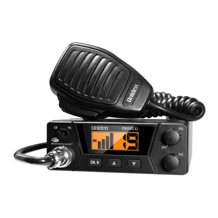
PARTS OF THE RADIO
Front

| No. | Name | Details |
| 1 | CB/PA Switch | Switches between CB Radio and PA systems |
| 2 | Volume/Power | Adjusts the volume. Turns radio on and off. |
| 3 | 4-Pin Mic | Plugs in microphone |
| 4 | CH9 | Sets the radio to CH9 (Emergency). |
| 5, 6 | Channel Selectors | Press  or or  to select which channel the radio will transmit or receive on. to select which channel the radio will transmit or receive on. |
| 7 | Squelch knob | Adjusts the level at which the radio squelches or suppresses weak radio signals |
NOTE: FCC rules reserve Channel 9 for motorist assistance and other emergency communications. Channel 9 should only be used in situations where there is immediate danger to the safety of individuals or the protection of property.
Back

| No. | Name | Details |
| 8 | Antenna Connector | Connects to a male PL-259 external antenna cable (antenna sold separately). |
| 9 | PA Speaker Jack | See Connecting external speakers. |
| 10 | External Speaker Jack | See Connecting external speakers. |
| 11 | 12 Volt DC Power Cord | Connects to DC power supply. |
Microphone
Press and hold the PTT button to transmit on the selected channel. Release the button to listen for a response.

NOTE: For the best sound quality, hold the microphone about 2 inches away from your mouth and speak in a normal voice.
NOTE: Make sure you have read and understood part 95 of the FCC rules and regulations before using the transmitter.
INSTALLATION
Connect the microphone
Align the microphone connector with the jack on the front of the radio. Push the connector in firmly and secure it with the locking screw.
Connect the power
You can connect the radio to any standard 12 volt DC power source, with either a positive or negative ground. If you don't know whether your power supply uses a positive or negative ground, consult the manual for your power supply or contact the manufacturer.

DO NOT connect this equipment to a power supply if you are not absolutely certain of the grounding type!
- Make sure your power supply is turned off.
- For power supplies with a NEGATIVE ground, connect the RED lead on the radio to the power supply's POSITIVE (+) pole, and connect the BLACK lead to the power supply's NEGATIVE (–) pole or to a neutral ground such as the chassis. Turn on your power supply.
- Turn the radio's Volume knob clockwise to power on the radio.
Installing the mounting bracket
When choosing the location for the radio's mounting bracket, keep the following things in mind:
- Pick a location that does not block your view, interfere with your vehicle's controls, or hinder your driving.
- Make sure the radio and microphone are not in front of an airbag.
- Pick a solid surface that can support the bracket and radio weight.
- Make sure there's enough room. (You may want to put the radio in the bracket when you're choosing where to install the bracket.)
Once you choose the location, use the included, self-tapping screws to attach the mounting bracket and the microphone bracket to your vehicle (you don't have to drill holes). Slide the radio into the bracket and use the included knobs to hold it at the preferred angle.
Connecting an external antenna

The antenna used for this radio must be installed at least 16.92 inches (43 cm) away from all persons. The antenna must not be collocated or used with any other antenna or transmitter.

Never operate your radio with no antenna or with a damaged antenna cable. This can damage the radio.
You will need to purchase an antenna to operate the radio. There are two basic types of mobile CB antennas – full-length whips and loaded whips – with a wide variety of mounts to suit different vehicle locations.
- Choose an antenna that matches the specifications of this radio.
- Follow the manufacturer's installation instructions carefully.
- Tune your antenna using a Standing-Wave Ratio (SWR) meter: set the radio to channel 20, and adjust the antenna until the SWR is as close as 1:1 as possible.
Connecting external speakers
Your radio supports two external speakers for remote monitoring and public address features. External speakers are sold separately.
To prevent feedback, direct all speakers away from the microphone.
| External monitor | PA speaker | |
| Function | Remote receiver monitoring or substitution for internal speaker | Public address broadcasts |
| Impedance | 8 Ohms | 8 Ohms |
| Rating | 3 Watts | 3 Watts |
| Connect to | EXT.SP. jack (⅛-in/3.5mm) | PA.SP. jack (⅛-in/3.5 mm) |
| Notes | The internal speaker is disabled when an external speaker is connected. | You must have a PA speaker connected to use the PA feature. |
Make sure the SWR is less than 2:1 before using the radio. An SWR higher than 2:1 can damage the transmitter.
Your Uniden dealer can help you select the antenna that is best for your needs. Consult the specifications in the back of this manual for detailed transmitter and antenna information.
OPERATION AND MAINTENANCE
Basic operation
| Turning the radio on | Turn the Volume knob clockwise until the display backlight comes on. |
| Turning the radio off | Turn the Volume knob counter-clockwise until it clicks and the display backlight turns off. |
| Selecting a channel | Press  or or  buttons to select a channel. buttons to select a channel. |
| Changing the volume | Turn the Volume knob clockwise to increase the volume; turn it counter-clockwise to decrease the volume. |
| Transmitting |
|
| Using the PA feature |
|
| Adjusting the squelch level |
|
| Using the Instant Channel 9 feature |
|
NOTE: Make sure you read and understood part 95 of the FCC rules and regulations before using the transmitter.
Maintenance
Every six to twelve months, check to make sure that:
- The Voltage Standing Wave Ratio (VSWR) is less than 2:1.
- All electrical connections are secure and free of corrosion.
- The antenna cable shows no wear or damage.
- All mounting screws are securely fastened.
TROUBLESHOOTING
If your radio is not performing to your expectations, please try these simple steps. If these steps don't solve your problem, visit www.uniden.com for help.
| Problem: | Things to try: |
| Radio won't turn on (no power) |
|
| Poor reception |
|
| Background noise |
|
| Weak transmission |
|
| PA won't broadcast |
|
Service and repair information
- Service, repair, or alignment should only be attempted by a qualified and/or licensed radio technician.
- When ordering parts, it is important to specify the correct model number of this radio.
- It is the user's responsibility to make sure the radio is operating in accordance with the FCC Citizens Radio Service regulations at all times.
SPECIFICATIONS
| General | |
| Channels | 40 AM |
| Frequency Range | 26.965 to 27.405 MHz |
| Frequency Control | Phase Locked Loop (PLL) synthesizer |
| Frequency Tolerance | ±0.005% |
| Operating Temperature | -30ºC to +50ºC |
| Microphone | Plug in type, electret |
| Input Voltage | 13.8 V DC nom. (+ or - ground) |
| Current Drain | TX full mod., 1.4A |
| RX | with max. audio output, 0.8A |
| Size | 4-7/8" W x 7-1/2" D x 1-3/4" H |
| Weight | 1 lb. 3 oz. |
| Antenna Connector | UHF, SO-239 |
| LCD Meter | Indicates relative RF output and received signal strength |
| Transmitter | |
| Power Output | 4 Watts |
| Modulation | Class B amplitude modulation |
| Freq. Response | 300-2500 Hz |
| Output Impedance | 50 ohms, unbalanced |
| Receiver | |
| Sensitivity | 0.8μV for 10 dB; (S + N) /N typical (limit 1.6μV) |
| Selectivity | 6 dB @ 7kHz, 70 dB @ 10kHz typical |
| Image Rejection | 65 dB typical |
| I.F. Frequency | Double Conversion Superheterodyne 1st 10.692 MHz 2nd 450 kHz |
| Automatic Gain Control (AGC) | less than 10dB change in audio output for inputs from 10 to 50,000 microvolts |
| Squelch | Adjustable; threshold less than 1.25μV |
| Audio Output Power | 3 watts max. into 8 ohms |
| Freq. Response | 300 to 2000 Hz |
| Distortion | less than 10% at 0.5 watts, 1000Hz |
| Internal Speaker | 8 ohms, 2 watts round |
Specifications and features are subject to change without notice.
Safety Notice
The antenna used for this radio must be properly installed and maintained and must provide a separation distance of at least 16.92 inches (43 cm) from all persons and must not be collocated or operated in conjunction with any other antenna or transmitter. Never transmit if any person is closer than the specified distance to the antenna.
Note that Uniden does not specify or supply any antenna with this transceiver. While a 0 dBi gain antenna is normal for a typical installation, the above limit applies to any antenna with up to 3 dBi gain.
Uniden contact information
You can get answers 24/7 at our website: www.uniden.com.
Documents / Resources
References
Download manual
Here you can download full pdf version of manual, it may contain additional safety instructions, warranty information, FCC rules, etc.
Advertisement


Need help?
Do you have a question about the PRO505XL and is the answer not in the manual?
Questions and answers