DeWalt DCS573, DCS573B, DCS573T1 - Circular Saw Manual
- Instruction manual (49 pages) ,
- Manual (44 pages) ,
- Original instructions manual (25 pages)
Advertisement
- 1 Overview
- 2 Definitions: Safety Alert Symbols and Words
- 3 Intended Use
- 4 GENERAL POWER TOOL SAFETY WARNINGS
- 5 ASSEMBLY AND ADJUSTMENTS
- 6 OPERATION
- 7 MAINTENANCE
- 8 Accessories
- 9 Repairs
- 10 Register Online
- 11 Documents / Resources
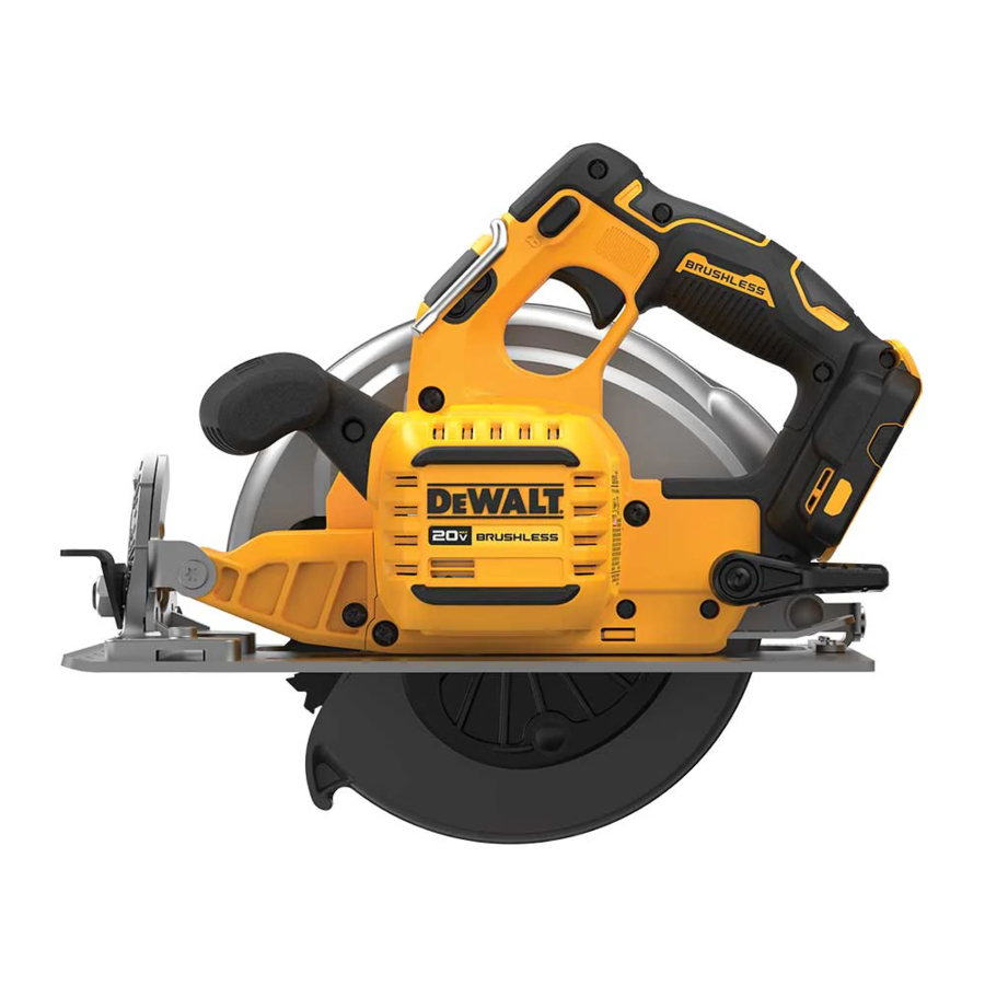
Overview

- Trigger switch lock-off button
- Trigger switch
- Battery pack
- Depth adjustment lever (Fig. E)
- Shoe
- Lower blade guard retracting lever
- Lower blade guard
- Blade clamping screw
- Kerf indicator
- Bevel adjustment lever
- Blade lock button
- Auxiliary handle
- Battery release button
- Hang hook
- Worklight
Definitions: Safety Alert Symbols and Words
This instruction manual uses the following safety alert symbols and words to alert you to hazardous situations and your risk of personal injury or property damage.

Indicates an imminently hazardous situation which, if not avoided, will result in death or serious injury.

Indicates a potentially hazardous situation which, if not avoided, could result in death or serious injury.

Indicates a potentially hazardous situation which, if not avoided, may result in minor or moderate injury.
 (Used without word) Indicates a safety related message.
NOTICE: Indicates a practice not related to personal injury which, if not avoided, may result in property damage.
Intended Use
These heavy-duty circular saws are designed for professional wood cutting applications. Do not cut metal, plastic, concrete, masonry or fiber cement materials. DO NOT use water feed attachments with this saw. DO NOT use abrasive wheels or blades. DO NOT use under wet conditions or in the presence of flammable liquids or gases. These heavy-duty saws are professional power tools. DO NOT let children come into contact with the tool. Supervision is required when inexperienced operators use this tool.
GENERAL POWER TOOL SAFETY WARNINGS

Read all safety warnings, instructions, illustrations and specifications provided with this power tool. Failure to follow all instructions listed below may result in electric shock, fire and/or serious injury.
The term "power tool" in the warnings refers to your mains‑operated (corded) power tool or battery‑operated (cordless) power tool.
- Work Area Safety
- Keep work area clean and well lit. Cluttered or dark areas invite accidents.
- Do not operate power tools in explosive atmospheres, such as in the presence of flammable liquids, gases or dust. Power tools create sparks which may ignite the dust or fumes.
- Keep children and bystanders away while operating a power tool. Distractions can cause you to lose control.
- Electrical Safety
- Power tool plugs must match the outlet. Never modify the plug in any way. Do not use any adapter plugs with earthed (grounded) power tools. Unmodified plugs and matching outlets will reduce risk of electric shock.
- Avoid body contact with earthed or grounded surfaces, such as pipes, radiators, ranges and refrigerators. There is an increased risk of electric shock if your body is earthed or grounded.
- Do not expose power tools to rain or wet conditions. Water entering a power tool will increase the risk of electric shock.
- Do not abuse the cord. Never use the cord for carrying, pulling or unplugging the power tool. Keep cord away from heat, oil, sharp edges or moving parts. Damaged or entangled cords increase the risk of electric shock.
- When operating a power tool outdoors, use an extension cord suitable for outdoor use. Use of a cord suitable for outdoor use reduces the risk of electric shock.
- If operating a power tool in a damp location is unavoidable, use a ground fault circuit interrupter (GFCI) protected supply. Use of a GFCI reduces the risk of electric shock.
- Personal Safety
- Stay alert, watch what you are doing and use common sense when operating a power tool. Do not use a power tool while you are tired or under the influence of drugs, alcohol or medication. A moment of inattention while operating power tools may result in serious personal injury.
- Use personal protective equipment. Always wear eye protection. Protective equipment such as a dust mask, non‑skid safety shoes, hard hat, or hearing protection used for appropriate conditions will reduce personal injuries.
- Prevent unintentional starting. Ensure the switch is in the off‑position before connecting to power source and/or battery pack, picking up or carrying the tool. Carrying power tools with your finger on the switch or energizing power tools that have the switch on invites accidents.
- Remove any adjusting key or wrench before turning the power tool on. A wrench or a key left attached to a rotating part of the power tool may result in personal injury.
- Do not overreach. Keep proper footing and balance at all times. This enables better control of the power tool in unexpected situations.
- Dress properly. Do not wear loose clothing or jewelry. Keep your hair, clothing and gloves away from moving parts. Loose clothes, jewelry or long hair can be caught in moving parts.
- If devices are provided for the connection of dust extraction and collection facilities, ensure these are connected and properly used. Use of dust collection can reduce dust‑related hazards.
- Do not let familiarity gained from frequent use of tools allow you to become complacent and ignore tool safety principles. A careless action can cause severe injury within a fraction of a second.
- Power Tool Use and Care
- Do not force the power tool. Use the correct power tool for your application. The correct power tool will do the job better and safer at the rate for which it was designed.
- Do not use the power tool if the switch does not turn it on and off. Any power tool that cannot be controlled with the switch is dangerous and must be repaired.
- Disconnect the plug from the power source and/ or remove the battery pack, if detachable, from the power tool before making any adjustments, changing accessories, or storing power tools. Such preventive safety measures reduce the risk of starting the power tool accidentally.
- Store idle power tools out of the reach of children and do not allow persons unfamiliar with the power tool or these instructions to operate the power tool. Power tools are dangerous in the hands of untrained users.
- Maintain power tools and accessories. Check for misalignment or binding of moving parts, breakage of parts and any other condition that may affect the power tool's operation. If damaged, have the power tool repaired before use. Many accidents are caused by poorly maintained power tools.
- Keep cutting tools sharp and clean. Properly maintained cutting tools with sharp cutting edges are less likely to bind and are easier to control.
- Use the power tool, accessories and tool bits etc. in accordance with these instructions, taking into account the working conditions and the work to be performed. Use of the power tool for operations different from those intended could result in a hazardous situation.
- Keep handles and grasping surfaces dry, clean and free from oil and grease. Slippery handles and grasping surfaces do not allow for safe handling and control of the tool in unexpected situations.
- Battery Tool Use and Care
- Recharge only with the charger specified by the manufacturer. A charger that is suitable for one type of battery pack may create a risk of fire when used with another battery pack.
- Use power tools only with specifically designated battery packs. Use of any other battery packs may create a risk of injury and fire.
- When battery pack is not in use, keep it away from other metal objects, like paper clips, coins, keys, nails, screws or other small metal objects, that can make a connection from one terminal to another. Shorting the battery terminals together may cause burns or a fire.
- Under abusive conditions, liquid may be ejected from the battery; avoid contact. If contact accidentally occurs, flush with water. If liquid contacts eyes, additionally seek medical help. Liquid ejected from the battery may cause irritation or burns.
- Do not use a battery pack or tool that is damaged or modified. Damaged or modified batteries may exhibit unpredictable behavior resulting in fire, explosion or risk of injury.
- Do not expose a battery pack or tool to fire or excessive temperature. Exposure to fire or temperature above 265°F (130°C) may cause explosion.
- Follow all charging instructions and do not charge the battery pack or tool outside the temperature range specified in the instructions. Charging improperly or at temperatures outside the specified range may damage the battery and increase the risk of fire.
- Service
- Have your power tool serviced by a qualified repair person using only identical replacement parts. This will ensure that the safety of the power tool is maintained.
- Never service damaged battery packs. Service of battery packs should only be performed by the manufacturer or authorized service providers.
Safety Instructions for All Saws
Cutting Procedures
![]()
Keep hands away from cutting area and the blade. Keep your second hand on auxiliary handle, or motor housing. If both hands are holding the saw, they cannot be cut by the blade.- Do not reach underneath the workpiece. The guard cannot protect you from the blade below the workpiece.
- Adjust the cutting depth to the thickness of the workpiece. Less than a full tooth of the blade teeth should be visible below the workpiece.
- Never hold the workpiece in your hands or across your leg while cutting. Secure the workpiece to a stable platform. It is important to support the work properly to minimize body exposure, blade binding, or loss of control.
- Hold the power tool by insulated gripping surfaces, when performing an operation where the cutting tool may contact hidden wiring. Contact with a "live" wire will also make exposed metal parts of the power tool "live" and could give the operator an electric shock.
- When ripping, always use a rip fence or straight edge guide. This improves the accuracy of cut and reduces the chance of blade binding.
- Always use blades with correct size and shape (diamond versus round) of arbor holes. Blades that do not match the mounting hardware of the saw will run off‑center, causing loss of control.
- Never use damaged or incorrect blade washers or bolt. The blade washers and bolt were specially designed for your saw, for optimum performance and safety of operation.
Further Safety Instructions for All Saws
Causes and Operator Prevention of Kickback:
- Kickback is a sudden reaction to a pinched, bound or misaligned saw blade, causing an uncontrolled saw to lift up and out of the workpiece toward the operator;
- When the blade is pinched or bound tightly by the kerf closing down, the blade stalls and the motor reaction drives the unit rapidly back toward the operator;
- If the blade becomes twisted or misaligned in the cut, the teeth at the back edge of the blade can dig into the top surface of the wood causing the blade to climb out of the kerf and jump back toward the operator.
Kickback is the result of saw misuse and/or incorrect operating procedures or conditions and can be avoided by taking proper precautions as given below:
- Maintain a firm grip with both hands on the saw and position your arms to resist kickback forces. Position your body to either side of the blade, but not in line with the blade. Kickback could cause the saw to jump backwards, but kickback forces can be controlled by the operator, if proper precautions are taken.
- When blade is binding, or when interrupting a cut for any reason, release the trigger and hold the saw motionless in the material until the blade comes to a complete stop. Never attempt to remove the saw from the work or pull the saw backward while the blade is in motion or kickback may occur. Investigate and take corrective actions to eliminate the cause of blade binding.
- When restarting a saw in the workpiece, center the saw blade in the kerf and check that saw teeth are not engaged into the material. If saw blade is binding, it may walk up or kickback from the workpiece as the saw is restarted.
- Support large panels to minimize the risk of blade pinching and kickback. Large panels tend to sag under their own weight. Supports must be placed under the panel on both sides, near the line of cut and near the edge of the panel.
- Do not use dull or damaged blades. Unsharpened or improperly set blades produce narrow kerf causing excessive friction, blade binding and kickback.
- Blade depth and bevel adjusting locking levers must be tight and secure before making cut. If blade adjustment shifts while cutting, it may cause binding and kickback.
- Use extra caution when making a "plunge cut" into existing walls or other blind areas. The protruding blade may cut objects that can cause kickback.
Lower Guard Function Safety Instructions
- Check lower guard for proper closing before each use. Do not operate the saw if lower guard does not move freely and close instantly. Never clamp or tie the lower guard into the open position. If saw is accidentally dropped, lower guard may be bent. Raise the lower guard with the retracting handle and make sure it moves freely and does not touch the blade or any other part, in all angles and depths of cut.
- Check the operation of the lower guard spring. If the guard and the spring are not operating properly, they must be serviced before use. Lower guard may operate sluggishly due to damaged parts, gummy deposits, or a buildup of debris.
- Lower guard should be retracted manually only for special cuts such as "plunge cuts" and "compound cuts." Raise lower guard by retracting handle and as soon as blade enters the material, the lower guard must be released. For all other sawing, the lower guard should operate automatically.
- Always observe that the lower guard is covering the blade before placing saw down on bench or floor. An unprotected, coasting blade will cause the saw to walk backwards, cutting whatever is in its path. Be aware of the time it takes for the blade to stop after switch is released.
Additional Safety Information
Never modify the power tool or any part of it. Damage or personal injury could result.
ALWAYS use safety glasses. Everyday eyeglasses are NOT safety glasses. Also use face or dust mask if cutting operation is dusty. ALWAYS WEAR CERTIFIED SAFETY EQUIPMENT:
- ANSI Z87.1 eye protection (CAN/CSA Z94.3),
- ANSI S12.6 (S3.19) hearing protection,
- NIOSH/OSHA/MSHA respiratory protection.
Some dust created by power sanding, sawing, grinding, drilling, and other construction activities contains chemicals known to the State of California to cause cancer, birth defects or other reproductive harm. Some examples of these chemicals are:
- lead from lead‑based paints,
- crystalline silica from bricks and cement and other masonry products, and
- arsenic and chromium from chemically‑treated lumber.
Your risk from these exposures varies, depending on how often you do this type of work. To reduce your exposure to these chemicals: work in a well ventilated area, and work with approved safety equipment, such as those dust masks that are specially designed to filter out microscopic particles.
- Wear protective clothing and wash exposed areas with soap and water. Allowing dust to get into your mouth, eyes, or lay on the skin may promote absorption of harmful chemicals. Direct particles away from face and body.
- Use the appropriate dust extractor vacuum to remove the vast majority of static and airborne dust. Failure to remove static and airborne dust could contaminate the working environment or pose an increased health risk to the operator and those in close proximity.
- Use clamps or other practical ways to secure and support the workpiece to a stable platform. Holding the work by hand or against your body is unstable and may lead to loss of control and injury.
- Air vents often cover moving parts and should be avoided. Loose clothes, jewelry or long hair can be caught in moving parts.
When not in use, place tool on its side on a stable surface where it will not cause a tripping or falling hazard. Some tools with large battery packs will stand upright on the battery pack but may be easily knocked over.
The label on your tool may include the following symbols. The symbols and their definitions are as follows:
| BPM | beats per minute | |
| V | volts | |
| min | minutes | |
| ⎓ or DC | direct current | |
| .../min | per minute | |
| RPM | revolutions per minute | |
| A | amperes | |
| Hz | hertz | |
| W | watts | |
| Wh | watt hours | |
| no | no load speed | |
| n | rated speed | |
| | safety alert symbol | |
 | wear respiratory protection | |
 | wear eye protection | |
 | Class II Construction (double insulated) | |
 | wear hearing protection | |
 | read all documentation | |
 | avoid staring at light | |
 or AC or AC | alternating current | |
| Ah | amp hours | |
ASSEMBLY AND ADJUSTMENTS
To reduce the risk of serious personal injury, turn unit off and remove battery pack before making any adjustments or removing/installing attachments or accessories. An accidental start‑up can cause injury.
Inserting and Removing the Battery Pack from the Tool
NOTE: Make sure your battery pack  is fully charged.

To Install the Battery Pack into the Tool Handle
- Align the battery pack
![]() with the rails inside the tool's handle (Fig. B).
with the rails inside the tool's handle (Fig. B). - Slide it into the handle until the battery pack is firmly seated in the tool and ensure that you hear the lock snap into place.
To Remove the Battery Pack from the Tool
- Press the release button
![]() and firmly pull the battery pack out of the tool handle.
and firmly pull the battery pack out of the tool handle. - Insert battery pack into the charger.
 and firmly pull the battery pack out of the tool handle.
Changing Blades
To Install the Blade
(Fig. A, D, E)


- Remove the battery.
- Using the lower guard retracting lever
![]() , retract the lower blade guard
, retract the lower blade guard ![]() and place blade on saw spindle against the inner clamp washer
and place blade on saw spindle against the inner clamp washer ![]() , making sure that the blade will rotate in the proper direction (the direction of the rotation arrow on the saw blade and the teeth must point in the same direction as the direction of rotation arrow on the saw). Do not assume that the printing on the blade will always be facing you when properly installed. When retracting the lower blade guard to install the blade, check the condition and operation of the lower blade guard to assure that it is working properly. Make sure it moves freely and does not touch the blade or any other part, in all angles and depths of cut.
, making sure that the blade will rotate in the proper direction (the direction of the rotation arrow on the saw blade and the teeth must point in the same direction as the direction of rotation arrow on the saw). Do not assume that the printing on the blade will always be facing you when properly installed. When retracting the lower blade guard to install the blade, check the condition and operation of the lower blade guard to assure that it is working properly. Make sure it moves freely and does not touch the blade or any other part, in all angles and depths of cut. - Place outer clamp washer
![]() on saw spindle with the beveled edge facing out. Make sure the 30 mm diameter on the blade side of the clamp fits into the 30 mm hole in the saw blade to ensure centering of the blade.
on saw spindle with the beveled edge facing out. Make sure the 30 mm diameter on the blade side of the clamp fits into the 30 mm hole in the saw blade to ensure centering of the blade. - Thread the blade clamping screw
![]() onto the saw spindle by hand (screw has right-hand threads and must be turned clockwise to tighten).
onto the saw spindle by hand (screw has right-hand threads and must be turned clockwise to tighten). - Depress the blade lock
![]() while turning the saw spindle with the blade wrench
while turning the saw spindle with the blade wrench ![]() stored underneath the battery compartment, until the blade lock engages and the blade stops rotating.
stored underneath the battery compartment, until the blade lock engages and the blade stops rotating. - Tighten the blade clamping screw firmly with the blade wrench.
 , retract the lower blade guard
  and place blade on saw spindle against the inner clamp washer
  , making sure that the blade will rotate in the proper direction (the direction of the rotation arrow on the saw blade and the teeth must point in the same direction as the direction of rotation arrow on the saw). Do not assume that the printing on the blade will always be facing you when properly installed. When retracting the lower blade guard to install the blade, check the condition and operation of the lower blade guard to assure that it is working properly. Make sure it moves freely and does not touch the blade or any other part, in all angles and depths of cut.
 on saw spindle with the beveled edge facing out. Make sure the 30 mm diameter on the blade side of the clamp fits into the 30 mm hole in the saw blade to ensure centering of the blade.
 onto the saw spindle by hand (screw has right-hand threads and must be turned clockwise to tighten).
 while turning the saw spindle with the blade wrench
  stored underneath the battery compartment, until the blade lock engages and the blade stops rotating.
NOTICE: Never engage the blade lock while saw is running, or engage in an effort to stop the tool. Never turn the saw on while the blade lock is engaged. Serious damage to your saw will result.
To Replace the Blade
(Fig. A, D, E)
- Remove the battery.
- To loosen the blade clamping screw
![]() , depress the blade lock
, depress the blade lock ![]() and turn the saw spindle with the blade wrench
and turn the saw spindle with the blade wrench ![]() , stored underneath the battery compartment, until the blade lock engages and the blade stops rotating. With the blade lock engaged, turn the blade clamping screw counterclockwise with the blade wrench (screw has right-hand threads and must be turned counterclockwise to loosen).
, stored underneath the battery compartment, until the blade lock engages and the blade stops rotating. With the blade lock engaged, turn the blade clamping screw counterclockwise with the blade wrench (screw has right-hand threads and must be turned counterclockwise to loosen). - Remove the blade clamping screw
![]() and outer clamp washer
and outer clamp washer ![]() . Remove old blade.
. Remove old blade. - Clean any sawdust that may have accumulated in the guard or clamp washer area and check the condition and operation of the lower blade guard as previously outlined. Do not lubricate this area.
- Select the proper blade for the application (refer to Blades). Always use blades that are the correct size (diameter) with the proper size and shape center hole for mounting on the saw spindle. Always assure that the maximum recommended speed (rpm) on the saw blade meets or exceeds the speed (rpm) of the saw.
- Follow steps 1 through 5 under To Install the Blade, making sure that the blade will rotate in the proper direction.
Lower Blade Guard
The lower blade guard is a safety feature that reduces the risk of serious personal injury. Never use the saw if the lower guard is missing, damaged, misassembled or not working properly. Do not rely on the lower blade guard to protect you under all circumstances. Your safety depends on following all warnings and precautions as well as proper operation of the saw. Check the lower blade guard for proper closing before each use. If the lower blade guard is missing or not working properly, have the saw serviced before using. To assure product safety and reliability, repair, maintenance and adjustment should be performed by an authorized service center or other qualified service organization, always using identical replacement parts.
Checking the Lower Guard
(Fig. A)
- Turn tool off and disconnect from power supply.
- Rotate the lower guard retracting lever
![]() from the fully closed position to the fully open position.
from the fully closed position to the fully open position. - Release the lever and observe the guard
![]() return to the fully closed position.
return to the fully closed position.
The tool should be serviced by a qualified service center if it:
- fails to return to the fully closed position,
- moves intermittently or slowly, or
- contacts the blade or any part of the tool in all angles and depth of cut.
Blades
To minimize the risk of eye injury, always use eye protection. Carbide is a hard but brittle material. Foreign objects in the workpiece such as wire or nails can cause tips to crack or break. Only operate saw when proper saw blade guard is in place. Mount blade securely in proper rotation before using, and always use a clean, sharp blade.
Do not cut metal, plastic, concrete, masonry or fiber cement materials with this saw.
| 7-1/4" (184 mm) Diameter | |
| Application | Teeth |
| Rip | 24 |
| General Purpose | 36 |
| Finish | 60 |
If you need assistance regarding blades, please contact your local DeWALT dealer.
Kickback
Kickback is a sudden reaction to a pinched, bound or misaligned saw blade, causing an uncontrolled saw to lift up and out of the workpiece toward the operator. When the blade is pinched or bound tightly by the kerf closing down, the blade stalls and the motor reaction drives the unit rapidly back toward the operator. If the blade becomes twisted or misaligned in the cut, the teeth at the back edge of the blade can dig into the top surface of the wood causing the blade to climb out of the kerf and jump back toward the operator.
Kickback is more likely to occur when any of the following conditions exists.
- IMPROPER WORKPIECE SUPPORT
- Sagging or improper lifting of the cut off piece can cause pinching of the blade and lead to kickback.
- Cutting through material supported at the outer ends only can cause kickback. As the material weakens it sags, closing down the kerf and pinching the blade.
![]()
- Cutting off a cantilevered or overhanging piece of material from the bottom up in a vertical direction can cause kickback. The falling cut off piece can pinch the blade.
- Cutting off long narrow strips (as in ripping) can cause kickback. The cut off strip can sag or twist closing the kerf and pinching the blade.
- Snagging the lower guard on a surface below the material being cut momentarily reduces operator control. The saw can lift partially out of the cut increasing the chance of blade twist.
- IMPROPER DEPTH OF CUT SETTING ON SAW
- To make the most efficient cut, the blade should protrude only far enough to expose one-half of a tooth as shown in Figure F. This allows the shoe to support the blade and minimizes twisting and pinching in the material. See the section titled Depth of Cut Adjustment.
- BLADE TWISTING (MISALIGNMENT IN CUT)
- Pushing harder to cut through a knot, a nail or a hard grain area can cause the blade to twist.
- Trying to turn the saw in the cut (trying to get back on the marked line) can cause blade twist.
- Overreaching or operating the saw with poor body control (out of balance), can result in twisting the blade.
- Changing hand grip or body position while cutting can result in blade twist.
- Backing up the saw to clear blade can lead to twist.
- MATERIALS THAT REQUIRE EXTRA ATTENTION
- Wet timber
- Green timber (material freshly cut or not kiln dried)
- Pressure treated timber (material treated with preservatives or anti-rot chemicals)
- USE OF DULL OR DIRTY BLADES
- Dull blades cause increased loading of the saw. To compensate, an operator will usually push harder which further loads the unit and promotes twisting of the blade in the kerf. Worn blades may also have insufficient body clearance which increases the chance of binding and increased loading.
- LIFTING THE SAW WHEN MAKING A BEVEL CUT
- Bevel cuts require special operator attention to proper cutting techniques – especially guidance of the saw. Both blade angle to the shoe and greater blade surface in the material increase the chance for binding and misalignment (twist) to occur.
- RESTARTING A CUT WITH THE BLADE TEETH JAMMED AGAINST THE MATERIAL
- The saw should be brought up to full operating speed before starting a cut or restarting a cut after the unit has been stopped with the blade in the kerf. Failure to do so can cause stalling and kickback.

Any other conditions which could result in pinching, binding, twisting, or misalignment of the blade could cause kickback. Refer to the sections Further Safety Instructions for All Saws and Blades for procedures and techniques that will minimize the occurrence of kickback.
Depth of Cut Adjustment
Maximum depth of cut is 2.5" (64 mm).

- Raise the depth adjustment lever
![]() to loosen.
to loosen. - To obtain the correct depth of cut, align the appropriate mark on the depth adjustment strap
![]() with notch
with notch ![]() on the upper blade guard.
on the upper blade guard. - Tighten the depth adjustment lever.
- For the most efficient cutting action using a carbide tipped saw blade, set the depth adjustment so that about one half of a tooth projects below the surface of the wood to be cut.
- A method of checking for the correct cutting depth is shown in Figure F. Lay a piece of the material you plan to cut along the side of the blade, as shown in the figure, and observe how much tooth projects beyond the material.
 with notch
  on the upper blade guard.
Adjusting Depth Adjustment Lever
(Fig. E)
It may be desirable to adjust the depth adjustment lever  . It may loosen in time and hit the shoe before tighten ing.
To Tighten the Lever:
- Hold depth adjustment lever
![]() and loosen the locknut
and loosen the locknut ![]() .
. - Adjust the depth adjustment lever by rotating it in the desired direction about 1/8 of a revolution.
- Retighten nut.
 .
.Bevel Angle Adjustment
(Fig. A, G)
The bevel angle adjustment mechanism can be adjusted between 0° and 57°.
To achieve better accuracy in cutting, use the fine adjustment markings located on the pivot bracket  .
.

- Raise the bevel adjustment lever
![]() to loosen.
to loosen. - Tilt the shoe to the desired angle by aligning the fine bevel pointer
![]() with the desired angle mark on the pivot bracket
with the desired angle mark on the pivot bracket ![]() .
. - Lower the bevel adjustment lever to retighten.
Bevel Detent
(Fig. A, G)
The DCS573 is equipped with a bevel detent feature. As you tilt the shoe  you will hear a click and feel the shoe stop at both 22.5 and 45 degrees. If either of these is the desired angle, retighten the lever
  by lowering it. If you desire another angle, continue tilting the shoe until the coarse bevel pointer
  or the fine pointer
  aligns with the desired mark.
Cut Length Indicator
(Fig. A)
The markings on the side of the shoe show the length of the slot being cut into the material at the full depth of the cut. The markings are in increments of 5 mm.
Kerf Indicator
The front of the saw shoe has a kerf indicator  for vertical and bevel cutting. This indicator enables you to guide the saw along cutting lines penciled on the material being cut. The kerf indicator lines up with the left (outer) side of the saw blade, which makes the slot or "kerf" cut by the moving blade fall to the right of the indicator. Guide along the penciled cutting line so that the kerf falls into the waste or surplus material.

Mounting and Adjusting the Parallel Fence
The parallel fence  is used for cutting parallel to the edge of the workpiece.

Mounting
- Slacken the parallel fence adjustment knob
![]() to allow the parallel fence to pass.
to allow the parallel fence to pass. - Insert the parallel fence
![]() in the shoe as shown.
in the shoe as shown. - Tighten the parallel fence adjustment knob
![]() .
.
 to allow the parallel fence to pass.
Adjusting
- Slacken the fence adjustment knob
![]() and set the parallel fence
and set the parallel fence ![]() to the desired width. The adjustment can be read on the parallel fence scale.
to the desired width. The adjustment can be read on the parallel fence scale. - Tighten the fence adjustment knob
![]() .
.
Mounting the Dust Extraction Port
(Fig. A, P)
Your circular saw is supplied with a dust extraction port.

To Install the Dust Extraction Port
- Fully loosen depth adjustment lever
![]() .
. - Place the shoe
![]() in the lowest position.
in the lowest position. - Align the left half of the dust extraction port
![]() over upper blade guard
over upper blade guard ![]() as shown. Be sure to insert the tab into the casting notch on the tool. When installed correctly, it will snap fully over the original depth of cut pointer.
as shown. Be sure to insert the tab into the casting notch on the tool. When installed correctly, it will snap fully over the original depth of cut pointer. - Align the right-hand piece
![]() with the left.
with the left. - Insert screws and tighten securely.
 over upper blade guard
  as shown. Be sure to insert the tab into the casting notch on the tool. When installed correctly, it will snap fully over the original depth of cut pointer.
 with the left.
Prior to Operation
- Make sure the guards have been mounted correctly. The saw blade guard must be in closed position.
- Make sure the saw blade rotates in the direction of the arrow on the blade.
- Do not use excessively worn saw blades.
OPERATION
To reduce the risk of serious personal injury, turn unit off and remove the battery pack before making any adjustments or removing/installing attachments or accessories. An accidental start‑up can cause injury.
Always observe the safety instructions and applicable regulations.
Proper Hand Position
To reduce the risk of serious personal injury, ALWAYS use proper hand position as shown.
To reduce the risk of serious personal injury, ALWAYS hold securely in anticipation of a sudden reaction.
Proper hand position requires one hand on the main handle  , with the other hand on the auxiliary handle
  .
.

LED Worklight
(Fig. A)
The LED worklight  is activated when the trigger switch is depressed. When the trigger is released, the worklight will stay illuminated for up to 20 seconds.
NOTE: The worklight is for lighting the immediate work surface and is not intended to be used as a flashlight.
Switching On and Off
For safety reasons the trigger switch  of your tool is equipped with a lock-off button
  .
.
Press the lock-off button to unlock the tool.
To run the tool, press the trigger switch . As soon as the trigger switch is released, the lock-off switch is automatically activated to prevent unintended starting of the machine.

NOTICE: Do not switch the tool ON or OFF when the saw blade touches the workpiece or other materials.
Workpiece Support
(Fig. J–M)
To reduce the risk of serious personal injury, support the work properly and hold the saw firmly to prevent loss of control.
Figures J and K show proper sawing position. Figures L and M show an unsafe condition. Hands should be kept away from cutting area.
To avoid kickback, ALWAYS support board or panel NEAR the cut (Fig. J and K). DON'T support board or panel away from the cut (Fig. L and M). When operating the saw, keep the cord away from the cutting area and prevent it from becoming hung up on the work piece.


ALWAYS DISCONNECT SAW BEFORE MAKING ANY ADJUSTMENTS! Place the work with its "good" side — the one on which appearance is most important — down. The saw cuts upward, so any splintering will be on the work face that is up when you saw it.
Cutting
(Fig. J, K)
Never attempt to use this tool by resting it upside down on a work surface and bringing the material to the tool. Always securely clamp the workpiece and bring the tool to the workpiece, securely holding the tool with two hands as shown in Figure J.
Place the wider portion of the saw shoe on that part of the workpiece which is solidly supported, not on the section that will fall off when the cut is made. As examples, Figure K illustrates the RIGHT way to cut off the end of a board. Always clamp work. Don't try to hold short pieces by hand! Remember to support cantilevered and overhanging material. Use caution when sawing material from below.
Be sure saw is up to full speed before blade contacts material to be cut. Starting saw with blade against material to be cut or pushed forward into kerf can result in kickback. Push the saw forward at a speed which allows the blade to cut without laboring. Hardness and toughness can vary even in the same piece of material, and knotty or damp sections can put a heavy load on the saw. When this happens, push the saw more slowly, but hard enough to keep working without much decrease in speed. Forcing the saw can cause rough cuts, inaccuracy, kickback, and over-heating of the motor. Should your cut begin to go off the line, don't try to force it back on. Release the switch and allow blade to come to a complete stop. Then you can withdraw the saw, sight anew, and start a new cut slightly inside the wrong one. In any event, withdraw the saw if you must shift the cut. Forcing a correction inside the cut can stall the saw and lead to kickback.
IF SAW STALLS, RELEASE THE TRIGGER AND BACK THE SAW UNTIL IT IS LOOSE. BE SURE BLADE IS STRAIGHT IN THE CUT AND CLEAR OF THE CUTTING EDGE BEFORE RESTARTING.
As you finish a cut, release the trigger and allow the blade to stop before lifting the saw from the work. As you lift the saw, the spring-tensioned telescoping guard will automatically close under the blade. Remember the blade is exposed until this occurs. Never reach under the work for any reason. When you have to retract the telescoping guard manually (as is necessary for starting pocket cuts) always use the retracting lever.
NOTE: When cutting thin strips, be careful to ensure that small cutoff pieces don't hang up on inside of lower guard.
Pocket Cutting
Never tie the blade guard in a raised position. Never move the saw backwards when pocket cutting. This may cause the unit to raise up off the work surface which could cause injury.
A pocket cut is one that is made in a floor, wall or other flat surface.

- Adjust the saw shoe so the blade cuts at desired depth.
- Tilt the saw forward and rest front of the shoe on material to be cut.
- Using the lower guard lever, retract lower blade guard to an upward position. Lower rear of shoe until blade teeth almost touch cutting line.
- Release the blade guard (its contact with the work will keep it in position to open freely as you start the cut). Remove hand from guard lever and firmly grip auxiliary handle
![]() , as shown in Figure O. Position your body and arm to allow you to resist kickback if it occurs.
, as shown in Figure O. Position your body and arm to allow you to resist kickback if it occurs. - Make sure blade is not in contact with cutting surface before starting saw.
- Start the motor and gradually lower the saw until its shoe rests flat on the material to be cut. Advance saw along the cutting line until cut is completed.
- Release trigger and allow blade to stop completely before withdrawing the blade from the material.
- When starting each new cut, repeat as above.
Dust Extraction
(Fig. P-R)
Risk of dust inhalation. To reduce the risk of personal injury, ALWAYS wear an approved dust mask.
A dust extraction port  is supplied with your tool.
The dust extraction port allows you to connect the tool to an external dust extractor, either using the AirLock™ system (DWV9000-XJ), or a standard 35 mm dust extractor fitment.

ALWAYS use a vacuum extractor designed in compliance with the applicable directives regarding dust emission when sawing wood. Vacuum hoses of most common vacuum cleaners will fit directly into the dust extraction outlet.
Hang Hook
(Fig. A)
To reduce the risk of serious personal injury, do not use the tool's hang hook to hang the tool from your body. DO NOT use the hang hook for tethering or securing the tool to a person or object during use. DO NOT suspend tool overhead or suspend objects from the hang hook.
To reduce the risk of injury from the circular saw falling on operators or bystanders, make sure it is supported securely when using the hang hook, or resting in a secure and stable location when not in use. Be sure to keep the area below clear to reduce the risk of the tool or off‑cut material falling and striking someone or something below.
The circular saw has a convenient hang hook  that allows it to hang on a suitable, stable structure between uses. The hang hook is not for tethering or securing the tool to a person or object during use when elevated.
Tool Connect™ Chip
To reduce the risk of injury, remove accessories from the tool chuck before any Tool Connect™ interaction.
Your tool is Tool Connect™ Chip ready and has a location for installation of a Tool Connect™ Chip.
Tool Connect™ Chip is an optional application for your smart device (such as a smart phone or tablet) that connects the device to utilize the mobile application for inventory management functions.
Refer to Tool Connect™ Chip Instruction Sheet for more information.
Installing the Tool Connect™ Chip

- Remove the retaining screws
![]() that hold the Tool Connect™ Chip protective cover
that hold the Tool Connect™ Chip protective cover ![]() into the tool.
into the tool. - Remove the protective cover and insert the Tool Connect™ Chip into the empty pocket
![]() .
. - Ensure that the Tool Connect™ Chip is flush with the housing. Secure it with the retaining screws and tighten the screws.
- Refer to Tool Connect™ Chip Instruction Sheet for further instructions.
 that hold the Tool Connect™ Chip protective cover
  into the tool.
 .
.MAINTENANCE
To reduce the risk of serious personal injury, turn unit off and remove the battery pack before making any adjustments or removing/installing attachments or accessories. An accidental start‑up can cause injury.
Your DeWALT power tool has been designed to operate over a long period of time with a minimum of maintenance. Continuous satisfactory operation depends upon proper tool care and regular cleaning.
Base Plate Adjustment
(Fig. G, H)
Your base plate has been factory set to assure that the blade is perpendicular to the base plate. If after extended use you need to re-align the blade, follow the directions below:

Adjusting for 90 Degree Cuts
- Return the saw to 0 degrees bevel.
- Place the saw on its side, and retract the lower guard.
- Set the depth of cut to 51 mm.
- Loosen the bevel adjustment lever (
![]() , Fig. G). Place a square against the blade and the base plate as shown in Figure G.
, Fig. G). Place a square against the blade and the base plate as shown in Figure G. - Using a wrench, turn the set screw (
![]() , Fig. H) on the underside of the base plate until the blade and the base plate are both in flush contact with the square. Retighten the bevel adjustment lever.
, Fig. H) on the underside of the base plate until the blade and the base plate are both in flush contact with the square. Retighten the bevel adjustment lever.
 , Fig. H) on the underside of the base plate until the blade and the base plate are both in flush contact with the square. Retighten the bevel adjustment lever.
Adjusting Bevel Adjustment Lever
It may be desirable to adjust the bevel adjustment lever  . It may loosen in time and hit the base plate before tighten ing.
To Tighten the lever:
- Hold the bevel adjustment lever
![]() and loosen the bevel locknut
and loosen the bevel locknut ![]() .
. - Adjust the bevel adjustment lever by rotating it in the desired direction about 1/8 of a revolution.
- Retighten nut.
 .
.Cleaning
Blow dirt and dust out of all air vents with clean, dry air at least once a week. To minimize the risk of eye injury, always wear ANSI Z87.1 approved eye protection when performing this procedure.
Never use solvents or other harsh chemicals for cleaning the non‑metallic parts of the tool. These chemicals may weaken the plastic materials used in these parts. Use a cloth dampened only with water and mild soap. Never let any liquid get inside the tool; never immerse any part of the tool into a liquid.
Lower Guard Cleaning
The lower guard should always rotate and close freely from a fully open to fully closed position. Always check for correct operation before cutting by fully opening the guard and letting it close. If the guard closes slowly or not completely, it will need cleaning or servicing. Do not use the saw until it functions correctly. To clean the guard, use dry air or a soft brush to remove all accumulated sawdust or debris from the path of the guard and from around the guard spring. Should this not correct the problem, it will need to be serviced by an authorized service center.
Blade Cleaning
A dull blade will cause inefficient cutting, overload on the saw motor, excessive splintering and increase the possibility of kickback. Change blades when it is no longer easy to push the saw through the cut, when the motor is straining, or when excessive heat is built up in the blade. It is a good practice to keep extra blades on hand so that sharp blades are available for immediate use. Dull blades can be sharpened in most areas.
Hardened gum on the blade can be removed with kerosene, turpentine, or oven cleaner. Anti-stick coated blades can be used in applications where excessive build-up is encountered, such as pressure treated and green timber.
Accessories
Since accessories, other than those offered by DeWALT, have not been tested with this product, use of such accessories with this product could be hazardous. To reduce the risk of injury, only DeWALT recommended accessories should be used with this product.
Recommended accessories for use with your product are available at extra cost from your local dealer or authorized service center. If you need assistance in locating any accessory, please contact DeWALT. Call 1-800-4-DeWALT (1-800-433-9258) or visit our website: www.dewalt.com.
Repairs
The charger and battery pack are not serviceable. There are no serviceable parts inside the charger or battery pack.
To assure product SAFETY and RELIABILITY, repairs, maintenance and adjustment (including brush inspection and replacement, when applicable) should be performed by a DeWALT factory service center or a DeWALT authorized service center. Always use identical replacement parts.
Register Online
Thank you for your purchase. Register your product now for:
- WARRANTY SERVICE: Registering your product will help you obtain more efficient warranty service in case there is a problem with your product.
- CONFIRMATION OF OWNERSHIP: In case of an insurance loss, such as fire, flood or theft, your registration of ownership will serve as your proof of purchase.
- FOR YOUR SAFETY: Registering your product will allow us to contact you in the unlikely event a safety notification is required under the Federal Consumer Safety Act. Register online at www.dewalt.com/account-login.
If you have questions or comments, contact us.
www.DeWALT.com
1-800-4-DeWALT
Documents / Resources
References
Download manual
Here you can download full pdf version of manual, it may contain additional safety instructions, warranty information, FCC rules, etc.
Download DeWalt DCS573, DCS573B, DCS573T1 - Circular Saw Manual
Advertisement


Need help?
Do you have a question about the DCS573 and is the answer not in the manual?
Questions and answers