DeWalt D24000 Manual
- Instruction manual (124 pages) ,
- Original instructions manual (101 pages) ,
- Instructions manual (28 pages)
Advertisement
- 1 Safety Guidelines Definitions
- 2 Safety Instructions
- 3 Technical data
- 4 Date Code Position
- 5 Package contents
- 6 Description
- 7 Electrical Safety
-
8
Assembly
- 8.1 Unpacking the machine and its parts
- 8.2 Mounting the motor frame to the support frame
- 8.3 Mounting the sliding table to the support frame assembly
- 8.4 Placing the machine into the water basin
- 8.5 Mounting the extension table
- 8.6 Installing the water pump
- 8.7 Mounting the water collectors
- 8.8 Mounting the cutting disc
- 8.9 Material thickness
- 8.10 Connecting the machine to the mains
-
9
Adjustment
- 9.1 Checking and adjusting the cutting depth
- 9.2 Checking that the crosscut travel is perpendicular to the fence
- 9.3 Checking that the cutting disc is perpendicular to the table
- 9.4 Checking and adjusting the bevel angle
- 9.5 Cutting a kerf
- 9.6 Checking and adjusting the scale
- 9.7 Locking the sliding table
- 9.8 Adjusting the water nozzles
- 9.9 Regulating the water flow
- 10 Instructions for use
- 11 Basic saw cuts
- 12 Maintenance
- 13 Documents / Resources
Safety Guidelines Definitions
The definitions below describe the level of severity for each signal word. Please read the manual and pay attention to these symbols.

Indicates an imminently hazardous situation which, if not avoided, will result in death or serious injury.

Indicates a potentially hazardous situation which, if not avoided, could result in death or serious injury.

Indicates a potentially hazardous situation which, if not avoided, may result in minor or moderate injury.
NOTICE: Indicates a practice not related to personal injury which, if not avoided, may result in property damage.
 Denotes risk of electric shock.
 Denotes risk of fire.
Safety Instructions

When using electric tools basic safety precautions should always be followed to reduce the risk of fire, electric shock and personal injury including the following.
Read all these instructions before attempting to operate this product and save these instructions.
SAVE THIS MANUAL FOR FUTURE REFERENCE
General
- Keep work area clean
Cluttered areas and benches can cause accidents. ![burn hazard]() Consider work area environment
Consider work area environment
Do not expose the tool to rain. Do not use the tool in damp or wet conditions. Keep the work area well lit (250-300 Lux). Do not use the tool where there is a risk of causing fire or explosion, e.g. in the presence of flammable liquids and gases.- Keep children away
Do not allow children, visitors or animals to come near the work area or to touch the tool or the mains cable. - Dress properly
Do not wear loose clothing or jewellery, as these can be caught in moving parts. Wear protective hair covering to keep long hair out of the way. Preferably wear suitable gloves and non-slip footwear. - Personal protection
Always use safety glasses. Use a face or dust mask whenever the operations may produce dust or flying particles. If these particles might be considerably hot, also wear a heat-resistant apron. Wear ear protection at all times. Wear a safety helmet at all times. - Guard against electric shock
Prevent body contact with earthed or grounded surfaces (e.g. pipes, radiators, cookers and refrigerators). Avoid touching the plugged-in mains cable when it is wet. Do not stand in pools when operating the tool. - Do not overreach
Keep proper footing and balance at all times. - Stay alert
Watch what you are doing. Use common sense.
Do not operate the tool when you are tired. - Secure workpiece
Use clamps or a vice to hold the workpiece. It is safer and it frees both hands to operate the tool. - Connect dust extraction equipment
If devices are provided for the connection of dust extraction and collection facilities, ensure that these are connected and properly used. - Remove adjusting keys and wrenches
Always check that adjusting keys and wrenches are removed from the tool before operating the tool. - Extension cables
Before use, inspect the extension cable and replace if damaged. When using the tool outdoors, only use extension cables intended for outdoor use and marked accordingly. - Use appropriate tool
The intended use is described in this instruction manual. Do not force small tools or attachments to do the job of a heavy-duty tool. The tool will do the job better and safer at the rate for which it was intended.
Do not force the tool.
The use of any accessory or attachment or performance of any operation with this tool other than those recommended in this instruction manual may present a risk of personal injury.
- Check for damaged parts
Before use, carefully check the tool and mains cable for damage. Check for misalignment and seizure of moving parts, breakage of parts, damage to guards and switches and any other conditions that may affect its operation. Ensure that the tool will operate properly and perform its intended function. Do not use the tool if any part is damaged or defective. Do not use the tool if the switch does not turn it on and off. Have any damaged or defective parts replaced by an authorised DEWALT repair agent. Never attempt any repairs yourself. - Unplug tool
Switch off and wait for the tool to come to a complete standstill before leaving it unattended. Unplug the tool when not in use, before changing any parts of the tools, accessories or attachments and before servicing. - Avoid unintentional starting
Be sure that the tool is switched off before plugging in. - Do not abuse cord
Never pull the cord to disconnect from the socket. Keep the cord away from heat, oil and sharp edges. - Store idle tools
When not in use, tools must be stored in a dry place and locked up securely, out of reach of children. - Maintain tools with care
Keep the tools in good condition and clean for better and safer performance. Follow the instructions for maintenance and changing accessories. Keep all handles and switches dry, clean and free from oil and grease. - Repairs
This tool is in accordance with the relevant safety regulations. Have your tool repaired by an authorised DEWALT repair agent. Repairs should only be carried out by qualified persons using original spare parts; otherwise this may result in considerable danger to the user.
Additional safety rules
- Do not use the machine if it is not fully assembled. Do not operate the machine as a hand-held power tool.
- Make sure all locking knobs and clamp handles are tight before starting any operation.
- Never place either hand in the cutting disc area when the machine is connected to the electrical power source.
- Never cut workpieces that require manual action closer than 15 cm from the rotating cutting disc.
- Never reach in the back of the cutting disc.
- Do not perform any operation freehand. Hold the workpiece firmly against the fence and the guide.
- Switch off the machine and wait for the cutting disc to stop before moving the workpiece or changing the settings.
- Never attempt to stop a machine in motion rapidly by jamming a tool or other means against the cutting disc; serious accidents can be caused unintentionally in this way.
- Keep the surrounding area of the machine well maintained and free of loose materials, e.g. debris and cut-offs.
- Check periodically that the motor air slots are clean and free of dust.
- Disconnect the machine from the mains before carrying out any maintenance work or when changing the cutting disc.
- Never perform any cleaning or maintenance work when the machine is still running and the head is not in the rest position.
- Select the correct cutting disc for the material to be cut.
- Use only the cutting discs specified in this manual. Never use grinding discs. Never use circular saw blades or any other types of toothed blades.
- The max. allowable speed of the cutting disc, or any other suitable accessory, must always be equal to or greater than the no-load speed of the machine specified on the nameplate.
- Do not use cutting discs that do not conform to the dimensions stated in the technical data. Do not use any spacers to make a disc fit onto the spindle.
- Inspect cutting discs before each use. Do not use chipped, cracked or otherwise defective discs.
- Ensure that the cutting disc is mounted correctly before use.
- Let the machine run at no-load in a safe position for at least 30 seconds. If there is a considerable vibration or if any other defect occurs, stop the machine and check it to determine the cause.
- Do not operate this machine without guards in place.
- Hold the workpiece firmly against the fence and guide during the cutting operation. Do not perform any operation freehand.
- Do not cut workpieces requiring a maximum depth of cut exceeding that of the cutting disc.
- Do not perform dry cuts. Dry cutting not only results in damage to the machine, it will also increase exposure to harmful airborne dust.
- Do not use cutting discs for side grinding.
- Do not cut metal materials.
- Always store cutting discs well-protected and in a dry place, out of reach of children.
- Do not make adjustments or parts substitutions to alter the factory settings. Technical alterations should only be carried out by the manufacturer, in compliance with the applicable safety requirements.
Take care that the connections are dry before activating the circuit and plugging in the machine.
- Keep water clear off the electrical parts of the tool and away from persons in the working area.
- Replacement of supply cord shall always be carried out by the manufacturer or his service agent.
![]()
After voltage recovery set ON/OFF switch to off before actuating RESET button of Residual Current Device (RCD).- Ensure your installation is provided with suitable cut out of "B" characteristic according to HD384.
Residual risks
The following risks are inherent to the use of these machines:
- injuries caused by touching the rotating parts
- injuries caused by disruption of the cutting disc
These risks are most evident:
- within the range of operation
- within the range of the rotating machine parts
In spite of the application of the relevant safety regulations and the implementation of safety devices, certain residual risks cannot be avoided.
These are:
- Impairment of hearing.
- Risk of accidents caused by the uncovered parts of the rotating cutting disc.
- Risk of injury when changing the disc.
- Risk of squeezing fingers when opening the guards.
Labels on tool
The following pictographs are shown on the tool:
 | Do not use recessed cutting discs. |
 | Wear safety goggles. |
 | Always wear regular working gloves while operating this tool. |
 | Always wear ear protection. |
 | Warning! Sharp edges. |
 | On/off switch: position I (on) and 0 (off). |
 | Carrying point |
 | Do not place your hands within this area. |
Technical data
| D24000 | ||||
| Voltage (U.K. & Ireland only) | Voltage V | 230 230/115 | ||
| Type | 2 | |||
| Power input | W | 1,600 / 1,500 | ||
| No-load speed | min-1 | 4,200 | ||
| Disc diameter | mm | 250 | ||
| Disc bore | mm | 25.4 | ||
| Disc body thickness | mm | 1.5 | ||
| Type of cutting disc | straight, non-recessed (continuous rim) | |||
| Max. peripheral speed cutting disc | min-1 | 5,000 | ||
| Bevel settings | ° | 22.5/45 | ||
| Max. ripping capacity | mm | 610 | ||
| Depth of cut at 90° | mm | 95 | ||
| Max. workpiece dimensions | Tile (granite) | cm | 64.5 x 64.5 x 1.2 | |
| Block (fired clay) | cm | 30.5 x 30.5 x 9.0 | ||
| Max. load | Tile (granite) | kg | 13 | |
| Block (fired clay) | kg | 20 | ||
| Overall dimensions | cm | 86.4 x 68.6 | ||
| Nominal weight | kg | 32 | ||
| LPA (sound pressure) | dB(A) | 90.0 | ||
| KPA ( sound pressure uncertainty) | dB(A) | 3.0 | ||
| LWA (sound power) | dB(A) | 103.0 | ||
| KWA ( sound power uncertainty) | dB(A) | 3.1 | ||
| Vibration total values (triax vector sum) determined according to EN 61029-1: Vibration emission value ah | ||||
| ah = | m/s² | 2.4 | ||
| Uncertainty K = | m/s² | 1.5 | ||
The vibration emission level given in this information sheet has been measured in accordance with a standardised test given in EN 61029 and may be used to compare one tool with another. It may be used for a preliminary assessment of exposure.
The declared vibration emission level represents the main applications of the tool. However if the tool is used for different applications, with different accessories or poorly maintained, the vibration emission may differ. This may significantly increase the exposure level over the total working period.
An estimation of the level of exposure to vibration should also take into account the times when the tool is switched off or when it is running but not actually doing the job. This may significantly reduce the exposure level over the total working period.
Identify additional safety measures to protect the operator from the effects of vibration such as: maintain the tool and the accessories, keep the hands warm, organisation of work patterns.
| Fuses | ||
| Europe | 230 V tools | 10 Amperes, mains |
| U.K. & Ireland | 230 V tools | 13 Amperes, in plugs |
| U.K. & Ireland | 115 V tools | 16 Amperes, mains |
NOTE: This device is intended for the connection to a power supply system with maximum permissible system impedance Zmax of 0.30 Ω at the interface point (power service box) of user's supply.
The user has to ensure that this device is connected only to a power system which fulfils the requirement above. If necessary, the user can ask the public power supply company for the system impedance at the interface point.
Date Code Position
(FIG. B1)
The Date Code (78), which also includes the year of manufacture, is printed into the housing.

Example:
2010 XX XX
Year of Manufacture
Package contents
The package contains:
1 Motor frame assembly
1 Support frame assembly
1 Water basin
1 Water pump
1 Cutting disc
1 Sliding table
1 Extension table
1 Edge guide
1 Rear water collector
1 Sliding table water collector
1 Small flange set
4 Hex screws
1 Hex key
1 Instruction manual
1 Exploded drawing
- Check for damage to the tool, parts or accessories which may have occurred during transport.
- Take the time to thoroughly read and understand this manual prior to operation.
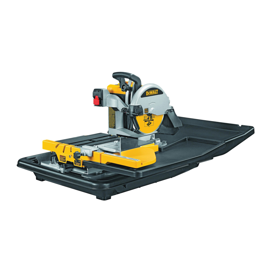
Description
(fig. A)
Your D24000 tile saw has been designed for professional wet tile cutting applications. Using the appropriate cutting disk, diameter 250 mm., it can cut concrete, brick, porcelain and ceramic materials. Providing optimum versatility, the machine performs the cutting operations of straight cutting (ripping), diagonal cutting, plunge cutting and bevel cutting easily, accurately and safely.
This machine is not to be used for any operation other than those mentioned in this manual.

- On/off switch
- Depth adjustment knob
- Operating handle
- Sliding table
- Edge guide
- Extension table
- Water nozzles
- Cutting disc
- Guard
- Depth stop
- Bevel adjustment knob
- Key storage
- Water basin
- Sliding table water collector
- Rear water collector
Electrical Safety
The electric motor has been designed for one voltage only. Always check that the power supply corresponds to the voltage on the rating plate.

Your tool is double insulated in accordance with EN 61029; therefore no earth wire is required.
115 V units have to be operated via a fail-safe isolating transformer with an earth screen between the primary and secondary winding.
In case of cord replacement the tool must only be repaired by an authorized service agent or by qualified electrician.
Mains Plug Replacement
(U.K. & Ireland only)
If a new mains plug needs to be fitted:
- Safely dispose of the old plug.
- Connect the brown lead to the live terminal in the plug.
- Connect the blue lead to the neutral terminal.
- Connect the yellow/green lead to the earth terminal
Follow the fitting instructions supplied with good quality plugs. Recommended fuse: 13 A.
Never use a light socket.
Never connect the live (L) or neutral (N) wires to the earth pin marked E or ![]() .
.
Fitting a Mains Plug to 115 V Units
(U.K. and Ireland Only)
- The plug should be fitted by a competent person. If you are in doubt, contact an authorized DEWALT repair agent or a qualified electrician.
- The plug fitted should be comply with BS EN 60309 (BS4343), 16 Amps, earthing contact position 4h.
Using an Extension Cable
If an extension cable is required, use an approved 3–core extension cable suitable for the power input of this tool (see technical data).The minimum conductor size is 1.5 mm2; the maximum length is 30 m. When using a cable reel, always unwind the cable completely.
Residual Current Device
The machine is equipped with a residual current device (RCD), which protects the user against electric shock by interrupting the circuit when a leakage current of 30 mA or greater is detected. For 115 V units the rated leakage current is 5 mA.
Never operate the machine without the RCD in place. Do not use the machine if the RCD does not function properly. For the RCD to work, the machine must be connected to an earthed wall socket. Periodically check the function of the RCD, pressing the TEST button.
Assembly
Prior to assembly always unplug the tool.
When assembling the machine, always follow the instructions in the order as described below.
Unpacking the machine and its parts
When moving the machine, always seek assistance. The machine is too heavy for one person to handle.
- Remove the loose packaging material from the box.
- Lift the machine parts out of the box.
- Remove any remaining packing material from the machine parts.
Mounting the motor frame to the support frame
(fig. B1)
- Place the support frame (16) on a relatively smooth and level surface.
- Place the motor frame (17) on the support frame aligning the holes in the foot (18) with the mounting holes (19).
- Insert a screw (20) into the holes.
- Tighten the screws using the hex key (21) provided.
Mounting the sliding table to the support frame assembly
(fig. B2 & B3)


- Make sure the lock (22) is in the unlock position.
- Hold the table in front of the frame, aligning the rollers (23) with the roller rail (24).
- Place the rear roller onto the round rail.
- Slide the table onto the rail, making sure that the bearings (25) locate in the slide rails (26).
- When the front of the table is approaching the frame, tilt the table slightly to clear the stop (27).
- Lock the table in position by rotating the pin (22) and pushing it into the hole (28) in the rail.
Placing the machine into the water basin

(fig. B4)
- Place the water basin (13) on a relatively smooth and level surface.
- Fit the plug (29) into the drain hole.
- Lift and hold the machine at the carrying points as shown.
- Lower the machine into the water basin as shown.
Mounting the extension table

(fig. C)
- Hold the extension table (6) in front of the right-hand side of the sliding table (4).
- Align the positioning pins (30) on the extension with the holes (31) in the sliding table.
- Place the extension against the sliding table.
- Tighten the clamp knob (32).
Installing the water pump

(fig. D1 & D2)
- Fit the hose (33) onto the fitting (34).
- Place the water pump (35) in the deep corner of the water basin (13).
- Route the power cable and the water tube over the bottom of the water basin as to avoid them from getting caught up by the sliding table.
Mounting the water collectors

(fig. E1 & E2)
Rear water collector
The rear water collector (15) collects water run-off when cutting large workpieces.
- Hold the water collector in position to the rear of the water basin.
- Slide the arms (36) underneath the edges (37) of the water basin until the recesses (38) locate behind the lugs.
- Tilt the rear of the water collector slightly until the collector snaps in position.
Sliding table water collector
The sliding table water collector (14) travels with the table and collects water run-off from large tiles and diagonal cuts.
- Hold the water collector in position to the right-hand side of the sliding table.
- Slide the arms (39) underneath the edges (40) of the sliding table until the recesses (41) locate behind the lugs.
- Tilt the rear of the water collector slightly until the collector snaps in position.
Mounting the cutting disc
(fig. F1 – F3)
The maximum diameter cutting disc that can be fitted is 254 mm.


- Using the Hex key (42) supplied, loosen the screw (43) on the side of the guard.
- Pull back the rubber side flap (44) and lift the guard (9) towards the rear.
- Depress the spindle lock button (45) with one hand, then take the supplied spanner (46) in the other hand to loosen the locking nut (47) by turning counterclockwise.
To use the spindle lock, press the button as shown and rotate the spindle by hand until you feel the lock engage. Continue to hold the lock button in to keep the spindle from turning.
- Remove the locking nut (47) and the outside flange collar (48).
- Install the cutting disc with the arrow facing the same way as the arrow on the guard.
- Replace the outer flange collar (48). Refer to Material Thickness for proper flange use.
- Tighten the locking nut (47) by turning clockwise while holding the spindle lock engaged with your other hand.
- Put the guard (9) back in position.
- Tighten the screw (43) on the side of the guard.
Never press the spindle lock while the cutting disc is rotating.
Material thickness
(fig. F2)
- The D24000 is fitted with a large diameter flange (48a), recommended for cutting material up to 80 mm in depth.
- A smaller flange (48b) is provided for when the 95 mm maximum cutting depth is required.
- The larger flange should be used whenever possible to ensure optimum cutting performance.
Connecting the machine to the mains
(fig. A)
- Make sure the on/off switch (1) is in the off position.
- Connect the mains plug to a mains supply.
- Arrange a drip loop in the cord connecting the machine to mains to prevent water from dripping onto the plug. The drip loop is that part of the cord below the level of the socket.
Adjustment
Prior to adjustment always unplug the tool.
Checking and adjusting the cutting depth
(fig. G)
The rim of the cutting disc should always be at least 5 mm below the table surface.

- Loosen the depth adjustment knob (2).
- Lower the arm to bring the cutting disc in lowest position.
- Tighten the depth adjustment knob (2).
- Make a dry run by pushing the table entirely through the cutting disc.
Check that the cutting disc does not foul the table. - If adjustment is required, proceed as follows:
- Loosen the depth adjustment knob (2).
- Loosen the wingnut (49) a few turns.
- Adjust the cutting depth stop (10) as necessary, making sure that the rim of the cutting disc is at least 5 mm below the table surface.
- Tighten the wingnut (49).
Checking that the crosscut travel is perpendicular to the fence

(fig. H1 & H2)
- Lower the arm to bring the cutting disc in lowest position.
- Move the table in front of the disc.
- Place a square (50) on the table and against the fence and just touching the disc as shown.
- Push the table through the cutting disc to check that the disc traverses parallel to the square.
- If adjustment is required, proceed as follows:
- Slacken the screws (51) holding the rail assembly to the frame.
- Position the rail adjuster (52) as necessary.
- With the square placed against the fence, check again that the disc traverses parallel to the square and adjust as necessary.
- Tighten the screws (51).
Checking that the cutting disc is perpendicular to the table

(fig. I1 - I3)
- Loosen the bevel clamp knob (11).
- Press the saw head to the right to ensure it is fully vertical and tighten the bevel clamp knob.
- Lower the arm to bring the cutting disc in lowest position.
- Move the table until underneath the disc.
- Place a square (50) on the table and against the disc as shown.
- If adjustment is required, proceed as follows:
- Loosen the bevel clamp knob (11) and turn the vertical position adjustment stop screw (53) in or out until the disc is at 90° to the table as measured with the square.
- If the bevel pointer (54) does not indicate zero on the bevel scale (55), loosen the screw (56) that secures the pointer and move the pointer as necessary.
Checking and adjusting the bevel angle

(fig. I3 & J)
- Loosen the bevel clamp knob (11) and move the saw head to the left.
This is the 45° bevel position. - If adjustment is required, proceed as follows:
- Turn the stopscrew (57) in or out as necessary until the pointer (54) indicates 45°.
Cutting a kerf
(fig. K)
The kerf indicator (58) helps to locate the path of the cutting disc.

- Switch on the machine and wait for the disc to reach full speed.
- Push the table entirely through the cutting disc to cut a kerf in the wheel (59).
- Switch off the machine.
If the kerf is worn, a new kerf can be created.
- Loosen the locking screw (60).
- Rotate the wheel (59) to expose uncut surface.
- Tighten the locking screw (60).
- Cut a new kerf following the instructions as described above.
Checking and adjusting the scale

(fig. L)
- Move the table until underneath the disc.
- Check the scale (61) on the fence using a tape measure (62) with the zero marking placed against the cutting disc.
- If adjustment is required, loosen the screws (63) that hold the scale (62) in place, adjust to the correct dimension and tighten the screws.
Locking the sliding table

(fig. M)
The table can be locked in the following positions:
- Front position (cutting disc freely accessible) (64).
- Plunge position (cutting disc over middle of table) (65).
- Outfeed position (cutting disc at fence) (66).
- Move the table (4) to the desired position.
- Lock the table by rotating the pin (22) and pushing it into the hole in the rail.
Adjusting the water nozzles
(fig. A & N)
The water nozzles (7) are adjustable to provide the necessary water flow of cooling water.

- Adjust the nozzle by moving the handle (67) into the required position.
- Maximum capacity (nozzles fully retracted) (68).
- Minimum overspray (nozzles in line with cutting disc) (69).
- Off position to eliminate water overspray between cuts and for replacing the cutting disc (70).
Regulating the water flow
(fig. O)
The flow restrictor (71) on the water tube can be adjusted to regulate the flow of cooling water towards the cutting disc.

- To reduce the flow, squeeze the restrictor.
- To increase the flow, release the restrictor.
Instructions for use
Ensure the machine is placed to satisfy your ergonomic conditions in terms of table height and stability. The machine site shall be chosen so that the operator has a good overview and enough free surrounding space around the machine that allows handling of the workpiece without any restrictions.
To reduce effects of vibration make sure the environment temperature is not too cold, machine and accessory is well maintained and the workpiece size is suitable for this machine.
- Always observe the safety instructions and applicable regulations.
- Check that the machine has been set up securely.
- Check that the workpiece is properly supported.
- Make sure the cutting disc is not contacting the workpiece before the machine is switched on.
- Allow the motor to reach full speed before cutting.
- Apply only a gentle pressure to the machine. Do not force the cutting action.
- Keep your hands out of the path of the cutting disc. Do not place your hands within the marked area as shown in fig. P.


Prior to operation:
- Install the appropriate cutting disc.
- Make sure all locking knobs and clamp handles are tight.
- Fill the water basin with the sufficient amount of water for the water pump to be fully submerged.

Switching on and off (fig. Q)
- To switch the machine on, set the on/off switch (1) to position I.
- To switch the machine off, set the on/off switch (1) to position 0.
Wired into the mains cable is the residual current device (RCD) containing the no-volt release switch and the motor overload protector with manual reset. In case of a power shut-off, proceed as follows:
- Make sure the on/off switch (1) is in the off position.
- Press the reset button on the RCD.
Locking the switch
- In order to avoid unauthorised use of the machine, lock the switch using a padlock.
Basic saw cuts
General handling
- Try a few simple projects using scrap material until you develop a "feel" for the machine.
- Always make dry runs (without power) before finish cuts so that you can check the path of the disc.
Vertical straight cross cut

(fig. R)
- Set the bevel angle to 0°.
- Lower the arm to bring the cutting disc in lowest position.
- Place the workpiece flat on the table and against the fence, with the finished side up. Align the marking on the workpiece with the marking in the kerf indicator.
- Keep both hands away from the path of the cutting disc.
- Switch the machine on and allow the cutting disc to reach full speed. Wait until the cutting disc is completely covered with water.
- Slowly feed the workpiece into the cutting disc, keeping it firmly pressed against the fence. Do not force. The cutting disc speed should be kept constant.
- After completing the cut, switch the machine off, allow the cutting disc to stop and remove the workpiece.
Bevel cross-cut
(fig. S)
Bevel angles can be set at 22.5° and 45°.

- Loosen the bevel clamp knob (11) and set the bevel as desired.
- Tighten the bevel clamp knob firmly.
- Proceed as for a vertical straight cross-cut.
Diagonal cut
(fig. T1 & T2)
The edge guide (5) allows cutting of angles at 45°.

- Place the edge guide with the mounting bracket (72) over the fence.
- Flip the guide fence (73) into position for the required application:
- Flip the fence to the right for cutting small pieces from large tiles.
- Flip the fence to the left for any other application.
- Set the parallel fence to the required distance.
- Tighten the knob (74) to secure the guide in place.
- Proceed as for a vertical straight cross-cut.
Plunge cut
(fig. U)
A plunge cut is used to remove the centre of a tile, e.g. for electrical outlets, drains, etc.

- Mark the area to be cut on both sides of the tile.
- Fit the appopriate size of cutting disc.
- Adjust the cutting depth to allow the cutting disc to saw only halfway through the workpiece.
- Place the workpiece flat on the table and against the fence, with the finished side up. Align the marking on the workpiece with the marking in the kerf indicator.
- Switch the machine on and allow the cutting disc to reach full speed. Wait until the cutting disc is completely covered with water.
- Move the table until the marking on the workpiece is underneath the disc.
- Lower the arm to feed the cutting disc into the workpiece. Do not overcut the mark. As soon as the marking has been cut, lock the arm into its highest position.
- Repeat as for the other markings.
- Turn the workpiece upside down. Proceed as described above for the second cuts to meet the first.
- After completing the cut, switch the machine off, allow the cutting disc to stop and remove the workpiece.
Grooving
(fig. V)
A groove is made into a tile e.g. to accommodate hidden wiring.

- Adjust the cutting depth as required.
- Place the workpiece flat on the table and against the fence, with the down side up. Align the marking on the workpiece with the marking in the kerf indicator.
- Proceed as for a vertical straight cross-cut.
- Repeat the procedure to make a wider groove.
Optional accessories
Since accessories, other than those offered by DEWALT, have not been tested with this product, use of such accessories with this tool could be hazardous. To reduce the risk of injury, only DEWALT recommended accessories should be used with this product.
| Range of cutting discs available | ||
| Type of disc | Dimensions (diameter x bore) | Usage |
| DT3733 | 250 x 25.4 mm | Ceramic tile |
| DT3734 | 250 x 25.4 mm | Porcelain/stone tile |
Consult your dealer for further information on the appropriate accessories.
Transporting
(fig. W1 & W2)
The detachable parts can be stored in the water basin for easy transportation.

- Drain the water basin. See "Maintenance".
- Remove the edge guide and the extension table.
- Lock the sliding table in position.
- Remove the water collectors.
- Lift the machine out of the water basin as shown.
- Place the collectors into the water basin in the orientation as shown.
- Turn the water basin upside down.
- Place the edge guide and the extension table into the water basin in the orientation as shown.
When carrying the machine, always seek assistance. The machine is too heavy for one person to handle.
Maintenance
Your DEWALT power tool has been designed to operate over a long period of time with a minimum of maintenance. Continuous satisfactory operation depends upon proper tool care and regular cleaning.
Draining the water basin
(fig. X)
The water basin must be drained after each use.

- Place the water pump on the tray (75).
- Place a suitable container under the drain plug (29).
- Remove the drain plug.
- Allow ample time for the liquid to drain.
- After the liquid has been drained, re-install the drain plug.
- Dispose of the liquid with due care for the environment.
Adjusting the table rolling resistance

(fig. Y)
To take out the clearance between the table and the rails, proceed as follows:
- Loosen the rail height screws (76).
- Adjust the rail height adjusters (77) until the table moves smoothly.
- Tighten the rail height screws.
Cleaning
Before use, carefully check the cutting disk guard to determine that it will operate properly. Ensure that mud, or work-piece particle cannot lead to blockage of one of the functions.
In case of workpiece fragments jammed between cutting disk and guard disconnect the machine from the power supply and follow the instructions given in section "Mounting the cutting disk". Remove the jammed parts and reassembling the cutting disk.
Keep the ventilation slots clear and regularly clean the housing with a soft cloth.
The following cleaning operations must be performed every day.
- Insert the water pump into a bucket of clean water and pump the water through the hose system.
- Wipe the rails and support arm with a grout sponge or a rag.
- Spray the water basin and the sliding table with clear water. Wipe any dust residue away with a grout sponge.
Lubrication
Your power tool requires no additional lubrication.
Documents / Resources
References
Download manual
Here you can download full pdf version of manual, it may contain additional safety instructions, warranty information, FCC rules, etc.
Advertisement


Need help?
Do you have a question about the D24000 and is the answer not in the manual?
Questions and answers