Table of Contents
Advertisement
Quick Links
MENARDS ITEM #641-5219
MODEL #2486FM-42-311
ATTACH YOUR RECEIPT HERE
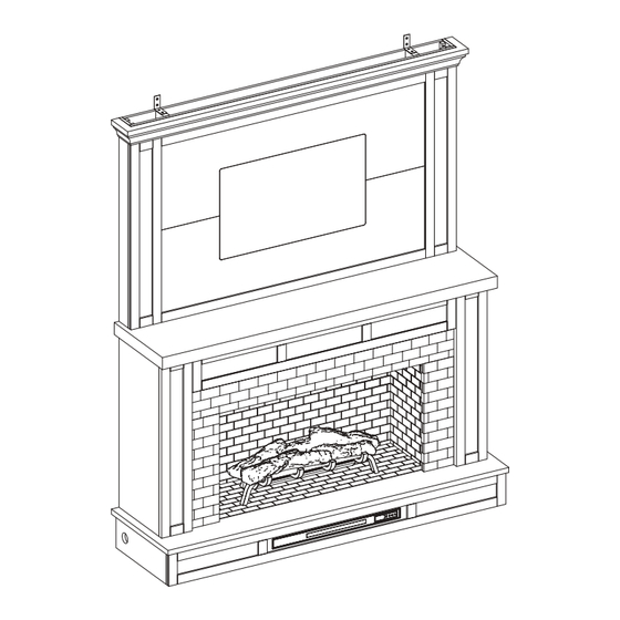
70" ELECTRIC FIREPLACE
ENTERTAINMENT CENTER
ASSEMBLY, CARE & USE INSTRUCTIONS
Serial Number__________________ Purchase Date__________________
Questions, problems, missing parts? Before returning to your retailer, call our customer service department
at 1-855-571-1044 9 a.m. - 5 p.m., EST, Monday - Friday. www.greentouchhome.com.
1
Advertisement
Table of Contents

Related Manuals for Greentouch 2486FM-42-311


Summary of Contents for Greentouch 2486FM-42-311
- Page 1 MENARDS ITEM #641-5219 MODEL #2486FM-42-311 ATTACH YOUR RECEIPT HERE 70" ELECTRIC FIREPLACE ENTERTAINMENT CENTER ASSEMBLY, CARE & USE INSTRUCTIONS Serial Number__________________ Purchase Date__________________ Questions, problems, missing parts? Before returning to your retailer, call our customer service department at 1-855-571-1044 9 a.m. - 5 p.m., EST, Monday - Friday. www.greentouchhome.com.
-
Page 2: Table Of Contents
TABLE OF CONTENTS Package Contents ................................3 Hardware Contents .................................4 Safety Information ................................4 Preparation ..................................8 Assembly Instructions ..............................8 CHANGE DOOR PANEL (OPTIONAL) ..........................26 Operating Instructions ..............................27 Care And Maintenance ..............................29 Troubleshooting ................................30 One-Year Limited Warranty ............................31 Replacement Parts List ..............................32... -
Page 3: Package Contents
PACKAGE CONTENTS TEMP PART DESCRIPTION QUANTITY PART DESCRIPTION QUANTITY Fireplace Grate Center Shelf Remote Control (Battery Included) Left Wall Right Wall Baffle Left Front Panel Firebox Top Panel Fireplace Brick Wall Right Front Panel Fireplace Glass Left Opening Plate Right Opening Plate Base and Heater Upper Opening Plate Top Cover Plate... -
Page 4: Hardware Contents
HARDWARE CONTENTS (NOT SHOWN ACTUAL SIZE) Wood Dowel Long Bolt Washer Back Panel Short Screw t l o Pivot Hinge Pivot Hinge L-Bracket Screw & x 10 x 53 screw Bracket x 10 L-Bracket L-Bracket Anchor Short Screw Long Screw Cam Lock Connecting Rod Touch-up Pen... -
Page 5: Important Instructions
SAFETY INFORMATION (CONTINUED) Modifications not approved by the party responsible for compliance could void user’s authority to operate the equipment. This Class B digital apparatus complies with Canadian ICES-003. IMPORTANT INSTRUCTIONS When using electrical appliances, basic precautions should always be followed to reduce the risk of fire, electric shock and injury to persons, including the following: DANGER •... - Page 6 SAFETY INFORMATION (CONTINUED) • Each surface intended to support a load shall have a corresponding statement in the use instructions specifying the maximum intended load for that surface in pounds (kilograms). • Risk of electric shock-connect this furnishing to a properly grounded outlet only. See Grounding Instructions. •...
- Page 7 SAFETY INFORMATION (CONTINUED) Electrical Connection • A 15-Amp, 120-volt, 60 Hz circuit with a properly grounded outlet is required. Preferably, the fireplace will be on a dedicated circuit as other appliances on the same circuit may cause the circuit breaker to trip or the fuse to blow when the heater is in operation.
-
Page 8: Preparation
PREPARATION Before beginning assembly of product, make sure all parts are present. Compare parts with package contents list and hardware contents list. If any part is missing or damaged, do not attempt to assemble the product. Estimated Assembly Time: 80 minutes Tools Required for Assembly (not included): Phillips screwdriver. - Page 9 ASSEMBLY INSTRUCTIONS (CONTINUED) 2. Attach the center shelf (B) to the right wall (D), with 2 short bolts (FF), using a phillips head screwdriver. Repeat for the left wall (C). Short Bolt 3. Align and attach the upper opening plate (I) to the assembled panels from Step 2. Secure with 3 short bolts (FF), using a phillips head screwdriver.
- Page 10 ASSEMBLY INSTRUCTIONS (CONTINUED) 4. Insert four wooden dowels (AA) into the bottom holes of the upper opening plate (I), align and attach the opening plates (G, H) to the upper opening plate (I). Adjust the metal plate on the opening plates (G, H) to align with the corresponding holes on the upper opening plate (I), securing with two screws (EE).
- Page 11 ASSEMBLY INSTRUCTIONS (CONTINUED) 6. Attach 2 connecting rods (PP) to center shelf (B), using a phillips head screwdriver. Connecting Rod 7. Attach the back panel support block (J2) to the connecting rods (PP), then install the cam locks (OO) using a phillips head screwdriver. Cam Lock...
- Page 12 ASSEMBLY INSTRUCTIONS (CONTINUED) 8. As shown in the diagram, insert the back panels (J1) along the grooves of the walls (C,D) and back panel support bracket (J2). 9. Attach 2 connecting rods (PP) to top (A), using a phillips head screwdriver. Connecting Rod...
- Page 13 ASSEMBLY INSTRUCTIONS (CONTINUED) Attach the top (A) from underneath with 6 short bolts (FF), using a phillips head screwdriver. Short Bolt Install the cam locks (OO) in to back panel support (J2), using a phillips head screwdriver. Cam Lock...
- Page 14 ASSEMBLY INSTRUCTIONS (CONTINUED) 12. Secure the back panel (J) to the product with the back panel screws and brackets (DD), using a phillips head screwdriver. Back Panel Screw and Bracket 13. Insert the fireplace glass front (T) into the assembled panels from the back side. Carefully lower the fireplace glass front (T) into the groove on the base (U).
- Page 15 ASSEMBLY INSTRUCTIONS (CONTINUED) 14. Insert the baffles (Q) into the fireplace grate (N) as shown in the diagram. 15. Install the fireplace grate (N) by inserting the bottom pins into the holes in the base (U). Secure with two short bolts (FF) using a phillips head screwdriver.
- Page 16 ASSEMBLY INSTRUCTIONS (CONTINUED) 16. Remove the film from the adhesive on the top of the fireplace grate (N) and place the fire log (M) on the center of the fireplace grate (N). Attach the USB cable from the heater into the USB port behind the fireplace grate (N). 17.
- Page 17 ASSEMBLY INSTRUCTIONS (CONTINUED) 18. Insert the fireplace brick wall (S) into the mantel, slotting it into the grooves on the base (U). Fasten the brackets to the back side of the opening plates (G, H) using two L-bracket screws (JJ) into the bracket. L-Bracket Screws 19.
- Page 18 ASSEMBLY INSTRUCTIONS (CONTINUED) 20. Hold the flip-down door (K) horizontally with the hinge side up, insert the pin of the left hinge to the plastic female thread on bottom left of the opening. Take the pivot hinge (GG) from the hardware bag and insert the pin of the hinge into the right side plastic female thread on the right bottom corner.
- Page 19 ASSEMBLY INSTRUCTIONS (CONTINUED) 22. Align and attach the boards (Z1, Z2), adjust the metal plate on the lower board (Z2) to align with the corresponding holes on the upper board (Z1), securing with four short screws (EE). Short Screw 23. Align and attach the side front panels (X) to the left and right sides with the assembly from Step 18, secure with screwing 8 short bolts (FF) using a phillips head screwdriver.
- Page 20 ASSEMBLY INSTRUCTIONS (CONTINUED) 24. Attach the side panels (W) to the side front panels (X) with 4 short bolts (FF) using a phillips head screwdriver. Short Bolt 25. Screw two L-bracket (KK) onto the top of the top cover plate (V) using four short screws (MM). L-Bracket Short Screw...
- Page 21 ASSEMBLY INSTRUCTIONS (CONTINUED) 26. Attach the top cover plate (V), securing from underneath with 4 short bolts (FF) using a phillips head screwdriver. Short Bolt 27. Lift the panel assembled in Step 22 onto the back of the mantel top, place it on the top edge of the top (A). Align the holes of the top (A) and secure the assembled panels with 6 short bolts, using a phillips head screwdriver.
- Page 22 ASSEMBLY INSTRUCTIONS (CONTINUED) 28. Align and attach the cover panel (Y), adjust the metal plate on the cover panel (Y) to align with the corresponding holes on the boards (Z1,Z2), securing with four short screws (EE). Short Screw 29. NOTE: Use the pre-assembled levelers on the base of the fireplace to level the unit. Twist the levelers counter-clockwise to increase the height, twist clockwise to decrease the height.
- Page 23 ASSEMBLY INSTRUCTIONS (CONTINUED) 30. Move the mantel into its final position on the wall. Use a pencil or paint tape to mark the location for mounting hardware on the wall as a guide. Make sure the marks are level and located at the desired height. Move the mantel away from the wall and drill guide holes for the marked points of the L-bracket on the wall and insert the anchor (LL) flush into the wall.
- Page 24 ASSEMBLY INSTRUCTIONS (CONTINUED) 31. With TV mount fully extended, move mantel closer to wall and guide TV mount through opening in panel. Leave a gap between the mantel and the wall approximately 6-10 inches to allow access to run TV power and AV cables behind the mantel.
- Page 25 ASSEMBLY INSTRUCTIONS (CONTINUED) 32. This is a good time to plug the fireplace into the power outlet. With the TV installed, get the help of another person to careful push the mantel into it’s final desired position against the wall. Take care not to pinch or crush any cords behind the unit.
-
Page 26: Change Door Panel (Optional)
CHANGE DOOR PANEL (OPTIONAL) Note: The pre-installed glass door panel can be switched out with the included wood door panel (L). 1. Remove the silicone trim along the outer edges of the glass panel on the inside of the flip down door. Start at a corner and pull to remove the four pieces. -
Page 27: Operating Instructions
OPERATING INSTRUCTIONS Control Panel Remote Control To use the remote control, first remove the plastic tab by gently pulling it out of remote control. Controls and Display The control panel will display the heater setting when the unit power is turned ON. Whichever control icon you press will display the current setting of the corresponding function. - Page 28 OPERATING INSTRUCTIONS (CONTINUED) Heater Function (Control Panel Only) • Press the HEATER ICON to display the current heater setting. • Press the HEATER ICON again to scroll down through the heater settings. Note: Long-hold the icon to quickly scroll through settings. •...
-
Page 29: Care And Maintenance
CARE AND MAINTENANCE • Make sure the unit is turned OFF, unplugged and the heating elements of heater are cool whenever you are cleaning the heater or fireplace. • Clean the metal trim using a water-dampened soft, clean cloth. DO NOT use brass polish or household cleaners as these products will damage the metal trim. -
Page 30: Troubleshooting
TROUBLESHOOTING PROBLEM POSSIBLE CAUSE CORRECTIVE ACTION Error E1 displayed on The overheat sensor has Unplug unit, wait 15-20 minutes, then the sensor will reset control panel. been engaged. itself. Plug the unit back in and turn on the heater. If the problem persists, call customer service (1-855-571-1044). -
Page 31: One-Year Limited Warranty
ONE-YEAR LIMITED WARRANTY The manufacturer warrants that your new electric fireplace is free from manufacturing and material defects for a period of one year from date of purchase, subject to the following conditions and limitations. Install and operate this electric fireplace in accordance with the installation and operating instructions furnished with the product at all times. -
Page 32: Replacement Parts List
FIRE LOG 4 Fireplace Grate GRATE D Remote Control RC-HE85EL02 KDI-02-26-311-M Heater-white Baffle GRATE D BAFFLE Fireplace Glass Front PU-1106x560-GLASS FRONT KD Hardware Pack PH-2486FM-42-311-HARDWARE PACK Flip-Down Door Handle PU-1860HW-04-BN HANDLE Flip-Down Door Hardware Set PU23-2468FM-LL/MM/NN Glass Clips GLASS CLIPS Leveler T-1007...
Need help?
Do you have a question about the 2486FM-42-311 and is the answer not in the manual?
Questions and answers