Table of Contents
Advertisement
MENARDS ITEM #641-5291
MODEL #1341FM-30-351
ATTACH YOUR RECEIPT HERE
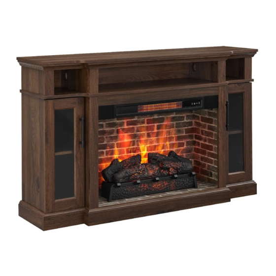
54" ELECTRIC FIREPLACE
ENTERTAINMENT CENTER
ASSEMBLY, CARE & USE INSTRUCTIONS
Serial Number__________________ Purchase Date__________________
Questions, problems, missing parts? Before returning to your retailer, call our customer service department
at 1-855-571-1044 9 a.m. - 5 p.m., EST, Monday - Friday. www.greentouchhome.com.
1
Advertisement
Table of Contents

Related Manuals for Greentouch 1341FM-30-351


Summary of Contents for Greentouch 1341FM-30-351
- Page 1 MENARDS ITEM #641-5291 MODEL #1341FM-30-351 ATTACH YOUR RECEIPT HERE 54” ELECTRIC FIREPLACE ENTERTAINMENT CENTER ASSEMBLY, CARE & USE INSTRUCTIONS Serial Number__________________ Purchase Date__________________ Questions, problems, missing parts? Before returning to your retailer, call our customer service department at 1-855-571-1044 9 a.m. - 5 p.m., EST, Monday - Friday. www.greentouchhome.com.
-
Page 2: Table Of Contents
TABLE OF CONTENTS Package Contents ................................3 Hardware Contents .................................4 Safety Information ................................4 Preparation ..................................8 Assembly Instructions ..............................8 Maximum Recommended Weight Loads........................20 Operating Instructions ..............................21 Care And Maintenance ..............................23 Troubleshooting ................................24 One-Year Limited Warranty ............................25 Replacement Parts List ..............................26... -
Page 3: Package Contents
PACKAGE CONTENTS PART DESCRIPTION QUANTITY PART DESCRIPTION QUANTITY Fireplace Brick Wall Corner Panel Fire Log Partition Panel Fireplace Grate Remote Control (Battery Center Shelf (with heater) Inside) Left Middle Wall Center Back Panel Right Middle Wall Back Panel Left Outer Wall Fireplace Glass Front Right Outer Wall Base... -
Page 4: Hardware Contents
HARDWARE CONTENTS (NOT SHOWN ACTUAL SIZE) Long Screw Wooden Dowel Connecting Locknut Back panel L-Bracket Short Screw mounting x 36 x 24 hardware (with x 24 screw) x 20 Shelf Pin Door Pull Hinge Hinge Screw Touch-up Pen Screw Tip Restraint x 24 Hardware SAFETY INFORMATION... - Page 5 SAFETY INFORMATION (CONTINUED) Modifications not approved by the party responsible for compliance could void user’s authority to operate the equipment. This Class B digital apparatus complies with Canadian ICES-003. IMPORTANT INSTRUCTIONS When using electrical appliances, basic precautions should always be followed to reduce the risk of fire, electric shock and injury to persons, including the following: DANGER •...
- Page 6 SAFETY INFORMATION (CONTINUED) • Each surface intended to support a load shall have a corresponding statement in the use instructions specifying the maximum intended load for that surface in pounds (kilograms). • Risk of electric shock-connect this furnishing to a properly grounded outlet only. See Grounding Instructions. •...
- Page 7 SAFETY INFORMATION (CONTINUED) Electrical Connection • A 15-Amp, 120-volt, 60 Hz circuit with a properly grounded outlet is required. Preferably, the fireplace will be on a dedicated circuit as other appliances on the same circuit may cause the circuit breaker to trip or the fuse to blow when the heater is in operation.
-
Page 8: Preparation
PREPARATION Before beginning assembly of product, make sure all parts are present. Compare parts with package contents list and hardware contents list. If any part is missing or damaged, do not attempt to assemble the product. Estimated Assembly Time: 50 minutes Tools Required for Assembly (not included): Phillips screwdriver ASSEMBLY INSTRUCTIONS 1. - Page 9 ASSEMBLY INSTRUCTIONS (CONTINUED) 2. Insert ten wooden dowels (BB) into the designated holes on the base (T). Align and attach the left outer wall (G) onto the dowels. Fasten the wall from underneath with two long screws (AA) using a Phillips Head Screwdriver. Repeat for right outer wall (H), left middle wall (E) and right middle wall (F).
- Page 10 ASSEMBLY INSTRUCTIONS (CONTINUED) 4. As shown in the diagram, insert the back panels (R) along the grooves of the middle walls (E, F) and outer walls (G, H). 5. Place the center shelf (D) upside down onto a scratch free surface such as a foam sheet that came in the packaging. Screw eight connecting rods (CC) into the designated holes on the back of the center shelf (D).
- Page 11 ASSEMBLY INSTRUCTIONS (CONTINUED) 6. Insert ten wooden dowels (BB) & eight locknuts (DD) into the corresponding holes on both left middle wall (E), right middle wall (F), left outer wall (G) and right outer wall (H). Turn the locking nut in clockwise direction up to 180° from the connection joint to properly secure the center shelf (D). x 10 Wooden Dowel Locknut...
- Page 12 ASSEMBLY INSTRUCTIONS (CONTINUED) 8. Insert eight wooden dowels (BB) into the top holes of center shelf (D), and insert eight locknuts (DD) into the corresponding holes of the corner panels (B) and partition panels (C). Turn the locking nut in clockwise direction up to 180° from the connection joint to properly secure the corner panels (B) and partition panels (C).
- Page 13 ASSEMBLY INSTRUCTIONS (CONTINUED) 10. Place the top (A) upside down onto a scratch free surface such as a foam sheet that came in the packaging. Screw eight connecting rods (CC) into the designated holes on the back of the top (A). Connecting Rod 11.
- Page 14 ASSEMBLY INSTRUCTIONS (CONTINUED) 12. Secure the back panels (R) and center back panel (Q) to the product using the back panel mounting hardware (EE). Fasten the screws with a Phillips screwdriver (As shown in diagram 12). x 20 Back panel mounting hardware 13.
- Page 15 ASSEMBLY INSTRUCTIONS (CONTINUED) 14. Remove the film from the adhesive on the top of the fireplace grate (N) and place the fire log (M) on the center of the fireplace grate (N). 15. Screw two L-bracket (FF) onto the fireplace brick wall (L) using four short screws (GG). L-Bracket Short Screw...
- Page 16 ASSEMBLY INSTRUCTIONS (CONTINUED) 16. Align the USB cable from behind through the cable hole on the fireplace brick wall (L). Attach the USB cable from the heater into the USB port behind the fireplace grate (N). Insert the fireplace brick wall (L) into the mantel, slotting it into the grooves on base (T).
- Page 17 ASSEMBLY INSTRUCTIONS (CONTINUED) 18. Place the door pull (II) into predrilled hole on right door (K), securing with two door pull screws. Repeat for remaining door pull (II). Door Pull 19. Align the hinges with the predrilled holes on the left door (J), securing each hinge with two hinge screws (KK). Repeat the same steps for the right door (K).
- Page 18 ASSEMBLY INSTRUCTIONS (CONTINUED) 20. NOTE: Use the pre-assembled levelers on the base of the fireplace to level the unit. Twist the levelers counter-clockwise to increase the height, twist clockwise to decrease the height. 1/2 in. 21. If you need to adjust the doors, do so in the following manner. To adjust door up or down, loosen screws (a) on both hinges, adjust door, and retighten screws.
- Page 19 ASSEMBLY INSTRUCTIONS (CONTINUED) WARNING: You must install the tip restraint hardware to help prevent any accidents or damage to the unit. We strongly recommend attaching the tip restraint hardware to a wall stud and your unit. For all other wall types, please visit your local hardware store to obtain the proper hardware.
-
Page 20: Maximum Recommended Weight Loads
MAXIMUM LOAD 6.8 kg / 15 lb MAXIMUM LOAD 6.8 kg / 15 lb MAXIMUM LOAD 6.8 kg / 15 lb SKU#641-5291/Model#1341FM-30-351 DISTRIBUTION: Greentouch USA Inc ADDRESS: 207 Byers Creek Rd Ste D Mooresville, NC 28117-6988 COUNTRY OF ORIGIN: VIETNAM MANUFACTURE DATE: JUN, 2022... -
Page 21: Operating Instructions
OPERATING INSTRUCTIONS Control Panel Remote Control To use the remote control, first remove the plastic tab by gently pulling it out of remote control. Controls and Display The control panel will display the heater setting when the unit power is turned ON. Whichever control icon you press will display the current setting of the corresponding function. - Page 22 OPERATING INSTRUCTIONS (CONTINUED) Heater Function • Press the HEATER ICON to display the current heater setting. • Press the HEATER ICON again to scroll down through the heater settings. Note: Long-hold the icon to quickly scroll through settings. • Set the heater to “HI” (High) to have the heater run continually. •...
-
Page 23: Care And Maintenance
CARE AND MAINTENANCE • Make sure the unit is turned OFF, unplugged and the heating elements of heater are cool whenever you are cleaning the heater or fireplace. • Clean the metal trim using a water-dampened soft, clean cloth. DO NOT use brass polish or household cleaners as these products will damage the metal trim. -
Page 24: Troubleshooting
TROUBLESHOOTING PROBLEM POSSIBLE CAUSE CORRECTIVE ACTION Error E1 displayed on The overheat sensor has Unplug unit, wait 15-20 minutes, then the sensor will reset control panel. been engaged. itself. Plug the unit back in and turn on the heater. If the problem persists, call customer service (1-855-571-1044). -
Page 25: One-Year Limited Warranty
ONE-YEAR LIMITED WARRANTY The manufacturer warrants that your new electric fireplace is free from manufacturing and material defects for a period of one year from date of purchase, subject to the following conditions and limitations. Install and operate this electric fireplace in accordance with the installation and operating instructions furnished with the product at all times. -
Page 26: Replacement Parts List
For replacement parts, call our customer service department at 1-855-571-1044 9 a.m. - 5 p.m., EST, Monday - Friday. www.greentouchhome.com. PART DESCRIPTION PART # 1341FM-30-351-TOP Corner Panel 1341FM-30-351-CORNER PANEL Left Middle Wall 1341FM-30-351-LEFT MIDDLE WALL Right Middle Wall 1341FM-30-351-RIGHT MIDDLE WALL Left Outer Wall 1341FM-30-351-LEFT OUTER WALL Right Outer Wall 1341FM-30-351-RIGHT OUTER WALL Shelf 1341FM-30-351-SHELF...
Need help?
Do you have a question about the 1341FM-30-351 and is the answer not in the manual?
Questions and answers
We get the off and F to light up on the panel control, no flame or brightness function, put new batteries in remote, nothing. Any way to jump start this unit? Unplugged and waited 5 min nothing works.
If the Greentouch 1341FM-30-351 unit shows "off" and "F" on the control panel and has no flame or brightness function, try the following troubleshooting steps:
1. Check Power Connection – Ensure the power cord is securely plugged into a standard 120V outlet.
2. Turn on the Unit – Press the power icon to turn the unit on.
3. Adjust Flame Brightness – If the unit is powered on but there is no flame effect, press the flame brightness button until the desired level is achieved.
If the issue persists, further troubleshooting may be needed.
This answer is automatically generated