Advertisement
SCOPE OF DELIVERY
| Part name | Quantity | |
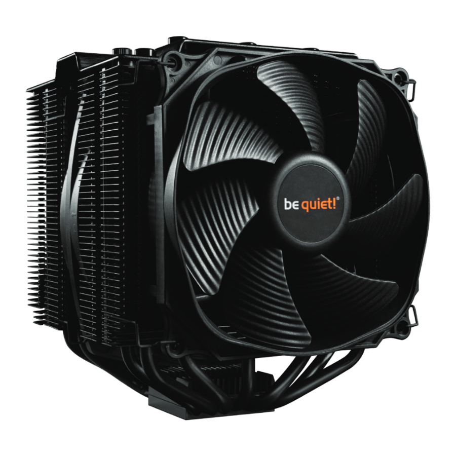
 | be quiet! Dark Rock Pro 4 cooler | 1 |
 | 135mm fan | 1 |
 | 120mm fan | 1 |
 | Intel backplate | 1 |
 | Intel mounting brackets | 2 |
 | Short AMD mounting brackets | 2 |
 | Cooler mounting bridge | 1 |
 | Intel spacer nuts | 4 |
 | Intel 115X/1366 nuts | 4 |
 | AMD spacer nuts | 4 |
 | Mounting bracket fastening screws | 4 |
 | Intel/AMD mounting bridge fastening screws | 2 |
 | Intel backplate screws | 4 |
 | AMD backplate screws | 4 |
 | O-rings | 4 |
 | Cross-tip screwdriver | 1 |
 | Thermal paste | 1 |
 | Fan clips | 2 |
 | AM3 washers | 4 |
 | Y cable | 1 |
Intel LGA 2011(-3) square ILM / LGA 2066
General
We recommend preparatory mounting of the cooler outside the PC case for subsequent installation.
Installation video

The following parts are needed for this:
1x Dark Rock Pro 4 CPU cooler (1), 1x 135mm fan (2), 1x 120mm fan (3), 2x Intel mounting brackets (5), 1x cooler mounting bridge (7), 4x Intel spacer nuts (8), 4x mounting bracket fastening screws (11), Intel/AMD mounting bridge fastening screws (12), 1x cross-tip screwdriver (16), 1x thermal paste (17), 4x fan clips (18), 1x Y cable (20)

Assembly of the cooler mounting frame
First screw the Intel spacer nuts (8) onto the threads of the socket frame. Place the Intel mounting brackets (5) over the Intel spacer nuts and screw these tight with the mounting bracket fastening screws (11). You can use the cross-tip screwdriver (16) for this.

First remove the protective foil from the underside of the cooler. Spread the thermal paste (17) on the surface of the CPU. The amount supplied is sufficient for one or two applications.

The thermal paste supplied is not suitable for human consumption. If swallowed, drink lots of water and urgently seek medical attention. Keep it out of the reach of children. Avoid contact with skin and eyes.

Position the cooler mounting bridge (7) centrally on the cooler (1). Next place the cooler unit over the CPU. Loosen both heatpipe caps that are found in the middle of the topside of the cooler (rotate as illustrated). Insert the Intel/AMD mounting bridge fastening screws (12) from above into the cooler mounting bridge (7) and then screw these alternately tight. You can use the cross-tip screwdriver (16) for this.

Subsequently retighten both heatpipe caps on the top side of the cooler.

Fasten the 120mm fan (3) using fan clips (18) onto the front side of the cooler. Slide the 135mm fan (2) between the two heatsinks and also fasten this with fan clips (18). Connect both fans using the the Y cable (20). Connect this to the CPU fan connector on the motherboard.

When dismantling the fans, push the notches of the fan clips (18) away from the fan.
Intel LGA 1150 / 1151 / 1155 / 1156 / 1366
General
We recommend preparatory mounting of the cooler outside the PC case for subsequent installation.
Installation video

The following parts are needed for this:
1x Dark Rock Pro 4 CPU cooler (1), 1x 135mm fan (2), 1x 120mm fan (3), 1x Intel backplate (4), 2x Intel mounting brackets (5), 1x cooler mounting bridge (7), 4x Intel 115X/1366 nuts (9), 4x mounting bracket fastening screws (11), 2x Intel/AMD mounting bridge fastening screws (12), 4x Intel backplate screws (13), 4x O-rings (15), 1x cross-tip screwdriver (16), 1x thermal paste (17), 4x fan clips (18), 1x Y cable (20)
Mounting the backplate
Position the Intel backplate screws (13) in the notches situated on the rear side of the Intel backplate (4). Pay attention in so doing to align with the holes specially drilled for each socket.

For fixing the backplate screws onto the Intel backplate use the O-rings (15). Once assembly of the Intel backplate for the respective Intel socket is complete, position it under the motherboard. In so doing make sure that the Intel backplate screws (13) are precisely positioned inside the motherboard holes.

Assembly of the cooler mounting frame
Screw the Intel 115X/1366 nuts (9) onto the previously positioned Intel backplate (4). Then position the Intel mounting brackets (5) over the Intel 115X/1366 nuts and affix these with the mounting bracket fastening screws (11). You can use the cross-tip screwdriver for this (16).

First remove the protective foil from the underside of the cooler. Spread the thermal paste (17) on the surface of the CPU. The amount supplied is sufficient for one or two applications.
The thermal paste supplied is not suitable for human consumption. If swallowed, drink lots of water and urgently seek medical attention. Keep it out of the reach of children.
Avoid contact with skin and eyes.

Position the cooler mounting bridge (7) centrally on the cooler. Next place the cooler unit over the CPU. Loosen both heatpipe caps that are found in the middle of the top side of the cooler. Insert the Intel/AMD mounting bridge fastening screws (12) from above into the cooler mounting bridge and then screw these alternately tight.

You can use the cross-tip screwdriver (16) for this. Subsequently retighten both heatpipe caps on the top side of the cooler.

Fasten the 120mm fan (3) using fan clips (18) onto the front side of the cooler. Slide the 135mm fan (2) between the two heatsinks and also fasten this with fan clips (18). Connect both fans using the the Y cable (20). Connect this to the CPU fan connector on the motherboard.

When dismantling the fans, push the notches of the fan clips (18) away from the fan.
AMD AM2(+) / AM3(+) / AM4 / FM1 / FM2(+)
General
We recommend preparatory mounting of the cooler outside the PC case for subsequent Installation video installation.
Installation video

The following parts are needed for this:
1x Dark Rock Pro 4 CPU cooler (1), 1x 135mm fan (2), 1x 120mm fan (3), 2x short AMD mounting brackets (6), 1x cooler mounting bridge (7), 4x AMD spacer nuts (10), 2x Intel/AMD mounting bridge fastening screws (12), 4x AMD backplate screws (14), 1x cross-tip screwdriver (16), 1x thermal paste (17), 4x fan clips (18), 4x AM3 washers (19), Y cable (20)

Assembly of the cooler mounting frame
To permit mounting of the cooler please remove both the plastic retainers of the AMD retention module. The factoryfitted backplate affixed to the rear side of the motherboard will be needed for subsequent installation of the cooler.
Note: To mount the Dark Rock Pro 4 on an AM3 motherboard, please use the AM3 washers (19), placing these over the backplate bolts protruding through the front side of the motherboard.

Place the 4x AMD spacer nuts (10) onto the backplate bolts protruding through the front side and affix both short AMD mounting brackets (6) with the AMD backplate screws (14).

Mounting the CPU cooler
First remove the protective foil from the underside of the cooler. Spread the thermal paste (17) on the surface of the CPU. The amount supplied is sufficient for one or two applications.

The thermal paste supplied is not suitable for human consumption. If swallowed, drink lots of water and urgently seek medical attention. Keep it out of the reach of children.
Avoid contact with skin and eyes.
Position the cooler mounting bridge (7) centrally on the cooler. Next place the cooler unit onto the CPU. Loosen both heatpipe caps that are found in the middle of the topside of the cooler (rotate as illustrated).

Insert the Intel/AMD mounting bridge fastening screws (12) from above into the cooler mounting bridge and then screw these alternately tight. You can use the cross-tip screwdriver (16) for this. Subsequently retighten both heatpipe caps on the topside of the cooler.

Fasten the 120mm fan (3) using fan clips (18) onto the front side of the cooler. Slide the 135mm fan (2) between the two heatsinks and also fasten this with fan clips (18). Connect both fans using the Y cable (20). Connect this to the CPU fan connector on the motherboard.

When dismantling the fans, push the notches of the fan clips (18) away from the fan.

Documents / ResourcesDownload manual
Here you can download full pdf version of manual, it may contain additional safety instructions, warranty information, FCC rules, etc.
Advertisement


Need help?
Do you have a question about the DARK ROCK PRO 4 and is the answer not in the manual?
Questions and answers