Table of Contents
Advertisement
Quick Links
Electric Boilers
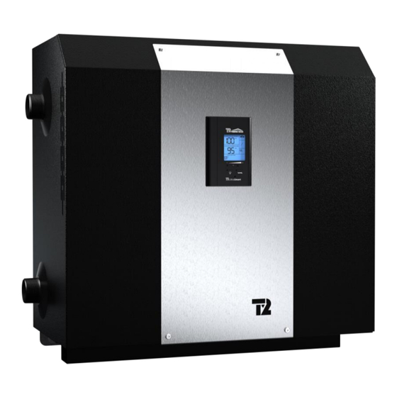
BTH ULTRA XL
Models ranging from 40 to 72 kW
INSTALLATION & OPERATION MANUAL
Your BTH ULTRA XL Electric Boiler has been carefully assembled and factory tested to
provide years of trouble-free service. The following information and safety measures are
provided to enable proper installation, operation, and maintenance of this product.
It is imperative that all persons who are expected to install, operate, or adjust this boiler should
read these instructions carefully.
Any questions regarding the operation, maintenance, service, or warranty of this electric boiler
should be directed to the supplier.
When all installation steps have been completed, keep this installation manual in a safe place
(close to the boiler) for future reference.
THERMO 2000 INC.
Printed In Canada
BTH ULTRA XL Electric Boilers Installation & Operation manual (Revision: July 2024)
Revision: July 2024
1
Advertisement
Table of Contents

Related Manuals for THERMO 2000 BTH ULTRA XL 240V


Summary of Contents for THERMO 2000 BTH ULTRA XL 240V
- Page 1 When all installation steps have been completed, keep this installation manual in a safe place (close to the boiler) for future reference. THERMO 2000 INC. Revision: July 2024 Printed In Canada BTH ULTRA XL Electric Boilers Installation & Operation manual (Revision: July 2024)
-
Page 2: Table Of Contents
Table of contents Section 1: Technical specification ..................4 Table 1 : Boiler specifications 240V / 1 phase ..............4 Table 2 : Boiler specifications 480V / 3 phases ..............4 Table 3 : Boiler specifications 600V / 3 phases .............. - Page 3 Figure 15 : UltraSmart Control Module ..................17 Figure 16 : Back of the controller ....................19 Figure 17 : Spare parts BTH ULTRA XL 240V-1 ph..............26 Figure 18 : Spare parts BTH ULTRA XL 480/600V - 3ph............27 BTH ULTRA XL Electric Boilers Installation & Operation manual (Revision: July 2024)
-
Page 4: Section 1: Technical Specification
Section 1: Technical specification Table 1 : Boiler specifications 240V / 1 phase Nominal Heating Maximum Capacity ULTRA XL amperage Elements Stages cable size (KW) 240V (Amp.) (277 V) (MCM) 166.7 8 x 5 kW 4 x 5 kW 183.3 4 x 6 kW 8 x 6 kW Table 2 : Boiler specifications 480V / 3 phases... -
Page 5: Table Of Figures Figure 1 : Boiler Dimensions
5 1/4 13 1/2 1 3/4 14 5/8 The dimensions provided are for indicative purposes only. Please contact Thermo 2000 for certified dimensions. Figure 1 : Boiler dimensions BTH ULTRA XL Electric Boilers Installation & Operation manual (Revision: July 2024) -
Page 6: Section 2: Introduction
General Safety Precautions Be sure to read and understand the entire Installation & operation manual before attempting to install or to operate this water heater. Pay particular attention to the following General Safety Precautions. Failure to follow these warnings could cause property damage, bodily injury or death. Should you have any problems understanding the instructions in this manual, STOP, and get help from a qualified installer or technician. -
Page 7: Section 3: Installation
Section 3: INSTALLATION The manufacturer’s warranty does not cover any damage or defect caused by installation, or attachment, or use of any special attachment other than those authorized by the manufacturer into, onto, or in conjunction with the water heater. The use of such unauthorized devices may shorten the life of the boiler and may endanger life and property. -
Page 8: Piping Installation
3.4 PIPING INSTALLATION The inlet and outlet piping of the boiler must be in conformity with the different configurations shown below. Make sure that the fluid flows is in the proper direction. Figure 2 : Mounting positions 3.4.1 Type of installation You will find below on figures 3 to 7 potential piping arrangements for a few typical systems. -
Page 9: Figure 4 : Installation With Fin-Tube Baseboards And A Multi-Pump Relay
Figure 4 : Installation with fin-tube baseboards and a multi-pump relay Figure 5 : Dual-energy installation in a primary-secondary circuit BTH ULTRA XL Electric Boilers Installation & Operation manual (Revision: July 2024) -
Page 10: Figure 6 : Dual-Energy Installation With A 3-Way Valve
Figure 6 : Dual-energy installation with a 3-way valve Figure 7 : Dual-energy installation with two condensing boilers and a TurboMax indirect water heater in a primary-secondary configuration BTH ULTRA XL Electric Boilers Installation & Operation manual (Revision: July 2024) -
Page 11: Boiler Piping Connection
3.4.2 Boiler piping connection boiler water returning to the potable water supply network (local regulation should be applied) Make sure you connect the accessories and the piping to the proper connection fittings as 3.4.8 Air eliminator indicated at figure 2 above and according to the selected mounting position. -
Page 12: Strainer
3.4.11 Strainer 3.5.2 Electrical supply of external 24V This component could be required on old heating accessories distribution systems made of steel or cast iron The maximum electrical consumption of 24vac that could carry sediments and sludge. If such external accessories connected to R&C terminals sediments accumulate at the bottom of the boiler must not exceed 30VA. -
Page 13: Thermostat Wiring
3.5.4 Thermostat wiring Zoning applications with motorized valves Connect the end switch contact of all motorized valve to terminals R & W on the boiler. Use a low voltage 24Vac thermostat designed for central heating system (do not use a 240Vac Use the dry contact on terminal PP of the boiler thermostat designed for electric baseboards). -
Page 14: Figure 10 : Connexions Without Three Way Valve
the thermostat no matter which heating mode is If the installation is made as shown on fig.6 selected. with a three-way valve : Install a three wire 18ga To do so: cable between the valve and the electric boiler Activate the dual energy function of the terminals. -
Page 15: Figure 12 : Wiring Diagram 240V-1Ph
Figure 12 : Wiring diagram 240V-1ph Figure 13 : Wiring Diagram 480/600V-3ph BTH ULTRA XL Electric Boilers Installation & Operation manual (Revision: July 2024) -
Page 16: Section 4: Adjustment Of The Controller
Section 4: ADJUSTMENT OF THE CONTROLLER 4.1 INTRODUCTION ❑ The BTH Ultra XL boiler is mainly designed to be Outdoor reset (the boiler target installed on closed circuit applications where the temperature modulate in relation to the water of the heating system flows directly from outdoor temperature) the boiler to the heating distribution system 4.2 DISPLAYED INFORMATION... -
Page 17: Operation Of The Interface
4.3 OPERATION OF THE INTERFACE The controller uses four push buttons at the bottom of the display to select and adjust the parameters. The button is used to access the configuration menu and confirm a selection. buttons are used to select an item or adjust a value. -
Page 18: Purge Delay Of The Pump
“15 sec to 60 min” delay where the pump will be ❑ The following tables show the values of the target temperature that will be obtained in relation to the kept running to enable the pump to circulate outdoor temperature. water into the system to equilibrate the heat in all PLINTHES CHAUFFANTES À... -
Page 19: Figure 16 : Back Of The Controller
This being done, the installer will have to access the configuration menu by pressing the button for 2 sec. until the first menu appears. The selection of the item or value is made by pressing the button and by pressing the button to get to the next menu. -
Page 20: Adjustments Of The Target Temperature By The User
Select the outdoor temperature at which no heating of the building is required (the outdoor 0°F à 105°F 75°F sensor has to be installed) Note 1: Once the operating parameters have been set, the controller will automatically come back to normal display screen. -
Page 21: Operation In Dual-Energy
target could simply be gradually increased by pressing Manual selection for the electricity or auxiliary boiler the + button or by re-setting the operating parameters mode. If the user wishes to manually select the electricity or using the tool menus The Boost menu can be cancelled by selecting “OFF”... -
Page 22: Section 5: Start Up Operation
Section 5: START UP OPERATION SAFETY PRECAUTIONS Before operating this boiler, be sure to read and follow these instructions, as well as the warnings printed in this manual. Failure to do so can result in unsafe operation of the boiler resulting in property damage, bodily injury, or death. -
Page 23: Section 6: Maintenance
Section 6: MAINTENANCE 6.1 INTRODUCTION large accumulation of deposits at the bottom of the unit. If so, close the isolating valves at the Properly maintained, your boiler will provide years of inlet and outlet of the boiler, remove heating dependable, trouble free service. It is recommended that element(s) and clean the inside of the tank with a regular routine maintenance program be established a strong jet of water. -
Page 24: Section 7: Trouble Shooting
Section 7: TROUBLE SHOOTING 7.1 TROUBLE SHOOTING TABLE PROBLEM CAUSES SOLUTION in “TARGET -There is no heating demand -Generate a heat demand The display shows when the outdoor sensor -Temporarily increase the value of this TEMP” is used and the icon setting on the controller configuration. - Page 25 The boiler water temperature at the -The room thermostat is not in -Adjust the thermostat anticipator (If outlet of the unit “BOILER T ”does constant demand. available) to obtain longer operating not get to the “BOILER TARGET T 0” -Some heating elements are cycles defective -Replace defective elements...
-
Page 26: Spare Parts
7.2 SPARE PARTS Figure 17 : Spare parts BTH ULTRA XL 240V-1 ph. Item Part number Description ZMC200-SV30PSI1 30 psi safety valve ZEL400-24024100 240V x 24Vac transformer ZEL100-24ACSPST Control relay ZEL100-24ACNO30 Power relay ZMC300-75P160C2 Pressure and temperature indicator ZEL200-LWCO24V Low water cutoff... -
Page 27: Pièces De Rechange, Identification Des Composantes
7.2 PIÈCES DE RECHANGE, IDENTIFICATION DES COMPOSANTES Figure 18 : Spare parts BTH ULTRA XL 480/600V - 3ph. Item Numéro de pièce Modèles Description ZMC200-SV30PSI1 Tous 30 psi safety valve ZEL400-48024100 480V 480V x 24Vac transformer ZEL400-60024100 600V 600V x 24Vac transformer ZEL100-24ACSPST Tous Control relay... - Page 28 Installation in which a relief valve (pressure) is not installed or Thermo 2000 Inc. hereby warrants that the BTH ULTRA XL tank installed in a normal residential service shall be exempt of any leak for ten (10) years from the if it is not functioning properly, or when it is not connected to purchase date.
Need help?
Do you have a question about the BTH ULTRA XL 240V and is the answer not in the manual?
Questions and answers