Table of Contents
Advertisement
BTH
M
odels ranging from 8 kW to 36 kW :
2 4 0 V o l t s ( 1 p h a s e ) & 6 0 0 V o l t s ( 3 p h a s e s ) .
USE & CARE MANUAL
WITH INSTALLATION INSTRUCTIONS FOR THE CONTRACTOR
Your BTH Electric Boiler has been carefully assembled and factory tested to provide years
of trouble-free service. The following information and safety measures are provided to
enable proper installation, operation, and maintenance of this product.
It is imperative that all persons who are expected to install, operate or adjust this boiler
should read these instructions carefully.
Any questions regarding the operation, maintenance, service or warranty of this electric
boiler should be directed to the supplier.
When all installation steps have been completed, insert this installation manual in its original
envelope, and keep in a safe place (close to the boiler) for future reference.
THERMO 2000 INCORPORATED
Printed in Canada
Electric Boilers
revision:August/06
Advertisement
Table of Contents

Subscribe to Our Youtube Channel
Related Manuals for THERMO 2000 BTH 8


Summary of Contents for THERMO 2000 BTH 8
- Page 1 When all installation steps have been completed, insert this installation manual in its original envelope, and keep in a safe place (close to the boiler) for future reference. THERMO 2000 INCORPORATED revision:August/06 Printed in Canada...
- Page 2 Electric Elements Total Wires Breakers Fuse 125% (in Watts) Model Watts Amp. Amp. Amp. Amp. BTH 8 5 000 3 000 ------ ------ 8 000 33.3 27 296 41.3 BTH 10 5 000 5 000 ------ ------ 10 000 41.6...
-
Page 3: Unit Description
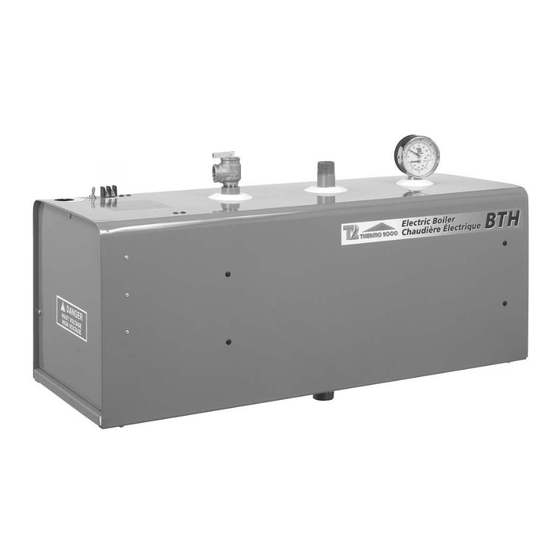
Unit description: Legend : A. Boiler Water Supply Connection ( 1 inch diameter, NPT male) B. Boiler Water Return Connection ( 1 inch diameter, NPT male) C. Safety Relief Valve ( ¾ inch NPT female ) D. Temperature & Pressure Gage (1/2 inch NPT female ) E. -
Page 4: General Safety Precautions
General Safety Precautions Be sure to read and understand the entire Use & Care Manual before attempting to install or to operate this water heater. Pay particular attention to the following General Safety Precautions. Failure to follow these warnings could cause property damage, bodily injury or death. Should you have any problems understanding the instructions in this manual, STOP, and get help from a qualified installer or technician. -
Page 5: Corrosive Atmosphere
CORROSIVE ATMOSPHERE The electric boiler should not be located near an air vent blowing a corrosive atmosphere or high humidity. The limited warranty is void when the failure of the electric boiler is due to a corrosive atmosphere. CHECK LIST Please check the identification tag on the unit to make sure you have the right model. -
Page 6: Installation
Installation BOILER WATER CONNECTIONS This electric boiler may be connected individually WARNING or in parallel with other boilers. If two or more boilers are connected, the “reverse-return piping” The manufacturer’s warranty does not cover method (whereby the boiler with the first return any damage or defect caused by installation, inlet also has the last supply outlet and so forth or attachment, or use of any special... - Page 7 the ASME Boiler and Pressure Vessel Code and These tanks incorporate a balloon-like bladder or limit the maximum operating boiler pressure. It is diaphragm. It is inflated, prior to filling the system, a safety device, not an operating control. to a pressure equal to the setting of the water pressure makeup regulator.
- Page 8 The CBE-EM dual-energy control will start up the Water pressure makeup regulator oil burner upon receiving the appropriate signal, Make-up systems must be employed as required even if the thermostat in the house is not calling by codes. An automatic fill valve must be used for heat.
- Page 9 Brun Bleu Noir Legeng/Légende: 10) T & P Gage/ Tridicateur THERMO 2000 inc. 1) Main water supply / Alimentation d'eau 11) Automatic air vent/ Purgeur d'air BTH 240V 2) Maintenance valve/ Valve d'entretien 12) Flow check valve/ Clapet antigravité...
- Page 10 Note 1: Bloc terminal (24 VAC) pour une installation avec le controleur bi-énergie Thermo 2000 modèle: "CBE-EM"/ Terminal block (24 VAC) for an installation with Thermo 2000 dual energy controller model: "CBE-EM" Note 2: Couper le cavalier lorsque vous utilisez le controleur bi-énergie Thermo 2000 modèle: "CBE-EM"/...
- Page 11 Note 1: Bloc terminal (24 VAC) pour une installation avec le controleur bi-énergie Thermo 2000 modèle: "CBE-EM"/ Terminal block (24 VAC) for an installation with Thermo 2000 dual energy controller model: "CBE-EM" Note 2: Couper le cavalier lorsque vous utilisez le controleur bi-énergie Thermo 2000 modèle: "CBE-EM"/...
- Page 12 Note 1: Bloc terminal (24 VAC) pour une installation avec le controleur bi-énergie Thermo 2000 modèle: "CBE-EM"/ Terminal block (24 VAC) for an installation with Thermo 2000 dual energy controller model: "CBE-EM" Note 2: Couper le cavalier lorsque vous utilisez le controleur bi-énergie Thermo 2000 modèle: "CBE-EM"/...
- Page 13 Note 1: Bloc terminal (24 VAC) pour une installation avec le controleur bi-énergie Thermo 2000 modèle: "CBE-EM"/ Terminal block (24 VAC) for an installation with Thermo 2000 dual energy controller model: "CBE-EM" Note 2: Couper le cavalier lorsque vous utilisez le controleur bi-énergie Thermo 2000 modèle: "CBE-EM"/...
- Page 14 Voir/see note 1 controleur bi-énergie Thermo 2000 modèle: "CBE-EM"/ OPTION: BTH-BE Terminal block (24 VAC) for an installation with Thermo 2000 dual energy controller model: "CBE-EM" Note 2: Couper le cavalier lorsque vous utilisez le controleur bi-énergie Thermo 2000 modèle: "CBE-EM"/ Cut open this jumper when using Thermo 2000 dual energy controller model: "CBE-EM"...
- Page 15 Voir/see note 1 controleur bi-énergie Thermo 2000 modèle: "CBE-EM"/ OPTION: BTH-BE Terminal block (24 VAC) for an installation with Thermo 2000 dual energy controller model: "CBE-EM" Note 2: Couper le cavalier lorsque vous utilisez le controleur bi-énergie Thermo 2000 modèle: "CBE-EM"/ Cut open this jumper when using Thermo 2000 dual energy controller model: "CBE-EM"...
- Page 16 Diagramme électrique/ Wiring diagram Contrôle Bi-énergy/ Dual control energy CBE-EM 120 Vac Transfo 24 Vac Lumière haut tarif/ High tarif light Relais BTH/ Sonde extérieur/ BTH Relay Bi-energie/ Dual energy Outdoor sensor Electrique/ Electric SPDT Mazout/ Oil Relais chaudière Relais/ Relay mazout/ Oil boiler Relay Interrupteur DPDT...
- Page 17 Basic Piping Schematics B T H LEGEND/ LÉGENDE : 8-DRAIN VALVE/ VALVE DRAINAGE 1- MAIN WATER SUPPLY/ ALIMENTATION D'EAU 2-MAINTENANCE VALVE/ VALVE D'ENTRETIEN 9-SAFETY VALVE/ SOUPAPE DE SÛRETÉ 10-TEMPERATURE AND PRESSURE GAUGE/ 3-CHECK VALVE/ CLAPET ANTI-RETOUR THERMOMANOMÈTRE 4-PRESSURE REDUCER/ RÉDUCTEUR DE PRESSION 11-AUTOMATIC AIR VENT/ PURGEUR D'AIR 5-EXPANSION TANK/ RÉSERVOIR DE DILATATION 12-FLOW CHECK VALVE (REQUIRED ON SYSTEMS...
- Page 18 TYP.: 105°F B T H TYP.: 90°F LEGEND/ LÉGENDE : 8-DRAIN VALVE/ VALVE DE DRAINAGE 1- MAIN WATER SUPPLY/ ALIMENTATION D'EAU 9-SAFETY VALVE/ SOUPAPE DE SÛRETÉ 2-MAINTENANCE VALVE/ VALVE D'ENTRTIEN 10-TEMPERATURE AND PRESSURE GAUGE/ THERMOMANOMÈT 3-CHECK VALVE/ CLAPET ANTI-RETOUR 11-AUTOMATIC AIR VENT/ PURGEUR D'AIR 4-PRESSURE REDUCER/ RÉDUCTEUR DE PRESSION 12-SUPPLY HEADER/ COLLECTEUR D'ALIMENTATION 5-EXPANSION TANK/ RÉSERVOIR DE DILATATION...
- Page 19 TYP.:150°F B T H TYP: 85°F LEGEND : 1- MAIN WATER SUPPLY/ ALIMENTATION D'EAU 11-AUTOMATIC AIR VENT/ PURGEUR D'AIR 2-MAINTENANCE VALVE/ VALVE D'ENTRETIEN 12-SUPPLY HEADER/ COLLECTEUR D'ALIMENTATION 3-CHECK VALVE/ CLAPET ANTI-GRAVITÉ 13-RETURN HEADER/ COLLECTEUR DE RETOUR 4-PRESSURE REDUCER/ RÉDUCTEUR DE PRESSION 14-RADIANT IN-FLOOR PIPING/ PLANCHER CHAUFFANT 5-EXPANSION TANK/ RÉSERVOIR DE DILATATION 15-INJECTION VALVE (SLOW OPENNING)/...
- Page 20 The following chart suggests the temperature PUMP AND PUMP SIZING drop (BWTD) to be used to calculate the pump flow rate. Boiler water temperature drop (BWTD) through the heating loop A simplified design method based on a 20°F PROPOSED BOILER WATER temperature drop (BWTD) between boiler outlet TEMPERATURE DROP THROUGH THE and inlet is commonly used.
- Page 21 Pipe sizing criteria creates a constant pressure (head) of one (1) psi Proper selection of pipe size is important to (pound per square inch). Pressure losses are efficient system operation. A large pipe size expressed either in “feet of water” or in psi. results in lower friction losses and may allow the Pump manufacturers usually prefer feet of water selection of smaller, more economical pump.
-
Page 22: Operation
Operation SAFETY PRECAUTIONS Each electric element has it own aquastat. Set the temperature on the aquastat using the Before operating this boiler, be sure to read knob graduated in degrees Celsius and and follow these instructions, as well as the Fahrenheit. - Page 23 If the heating system is designed to use only a PUMP POWER SUPPLY single pump, then to minimize flow by gravity Use a relay (Honeywell #RA-889, RA-89A) or and heat loss during non-draw periods, a flow the secondary contact of a zone valve (if the check must be installed.
-
Page 24: Maintenance
Maintenance Properly maintained, your boiler will provide years of replaced with the same model or its equivalent. Do not dependable, trouble free service. It is recommended plug the outlet of this valve if a dripping condition that a regular routine maintenance program be occurs. - Page 25 Thermo 2000 Inc. warrants to the original purchaser that the BTH tank installed in a unit. This warranty limits its beneficiary’s rights. Nevertheless, the beneficiary may have commercial setting for ten years, the first (5) years in full and years six (6) through other rights, which vary from state to state.
Need help?
Do you have a question about the BTH 8 and is the answer not in the manual?
Questions and answers