Table of Contents
Advertisement
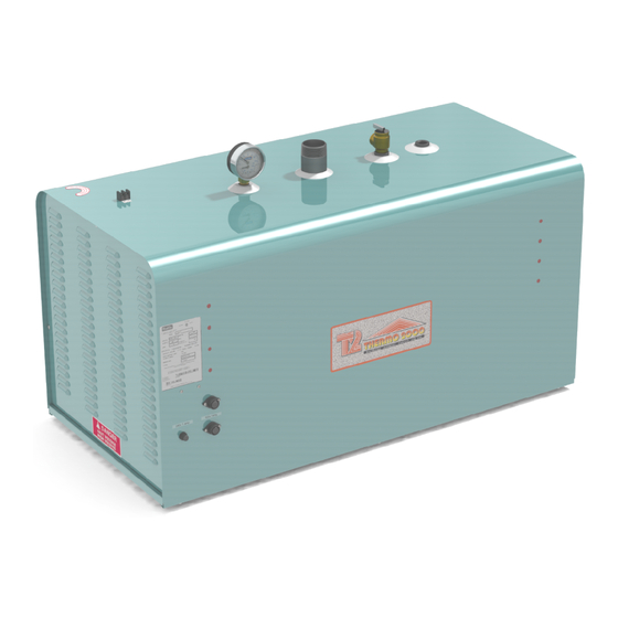
DTH
M
odels ranging from 42 kW to 144 kW :
24 0 V o lt s ( 1 ph as e ) , 4 8 0 an d 6 0 0 V o lt s ( 3 p h a s es ) .
USE & CARE MANUAL
WITH INSTALLATION INSTRUCTIONS FOR THE CONTRACTOR
Your DTH's Electric Boiler has been carefully assembled and factory tested to provide years
of trouble-free service. In order to ensure performance, the following information and safety
precautions are provided to enable proper installation, operation, and maintenance of this
product.
It is imperative that all persons who are expected to install, operate or adjust this electric
boiler should read these instructions carefully to fully understand how to do so.
Any questions regarding the operation, maintenance, service or warranty of this electric
boiler should be directed to the supplier.
When all installation steps have been completed, insert this installation manual in its original
envelope, and keep in a safe place (close to the boiler) for future reference.
THERMO 2000 INC.
Printed in Canada
Electric Boilers
Revision June 2014
Advertisement
Table of Contents

Subscribe to Our Youtube Channel
Related Manuals for THERMO 2000 DTH 45


Summary of Contents for THERMO 2000 DTH 45
- Page 1 When all installation steps have been completed, insert this installation manual in its original envelope, and keep in a safe place (close to the boiler) for future reference. THERMO 2000 INC. Revision June 2014 Printed in Canada...
-
Page 2: Section 1 : Dimensions & Specifications
Élements Power Secondary Model Stages Aquastats Lights Sequencers (277V) contactors contactors DTH 45 9 X 5KW DTH 54 9 X 6KW DTH 60 12 X 5KW DTH 72 12 X 6KW 12 X 5KW DTH 78 3 X 6KW DTH 90... - Page 3 Élements Power Secondary Model Stages Aquastats Lights Sequencers (347V) contactors contactors DTH 45 9 X 5KW DTH 54 9 X 6KW DTH 60 12 X 5KW DTH 72 12 X 6KW 12 X 5KW DTH 78 3 X 6KW DTH 90...
- Page 4 Figure 1 : Component identification DTH Electric Boilers USE & CARE MANUAL , Page (Revision June 2014)
-
Page 5: General Safety Precautions
General Safety Precautions Be sure to read and understand the entire Use & Care Manual before attempting to install or to operate this electric boiler. Pay particular attention to the following General Safety Precautions. Failure to follow these warnings could cause property damage, bodily injury or death. Should you have any problems understanding the instructions in this manual, STOP, and get help from a qualified installer or technician. -
Page 6: Section 3 : Installation
Section 3 : INSTALLATION WARNING Minimum clearances for adequate inspection and servicing are listed in the following table: The manufacturer’s warranty does not cover any damage or defect caused by installation, Table 4: Boiler clearance or attachment, or use of any special Left side 14 inches attachment other than those authorized by... - Page 7 Use only clean, new piping for boiler water lines. bleeding, prevent cavitation at the pump inlet Local codes or regulations shall govern the and prevent water from boiling within the exact type of material to be used. system; all this is accomplished with minimal Insulate all pipes containing hot water, addition of new water.
- Page 8 3.4.7 Circulator zoning recommendations Table 5: Temperature rise through the boiler The preferred location of the circulator pump for each zone is on the boiler supply side, with the PROPOSED BOILER WATER expansion tank between the boiler and the TEMPERATURE RISE THROUGH THE pump.
- Page 9 Model higher than 4 feet per 100 feet. DTH 42 28,8 14,4 Fluid velocity should be above 1-1/2 to 2 feet per DTH 45 30,8 15,4 10,3 second in order to carry entrained air along to a DTH 48 32,9...
-
Page 10: Electrical Power Supply
3.5 ELECTRICAL POWER SUPPLY 3.7.1.2 Multiple heating zones Wiring must conform to the National Electrical Code and to state or local code requirements. Zone valve zoning Connect the low voltage thermostat to the zone The electric boiler must be electrically grounded valve. - Page 11 3.8 CBE-EM DUAL ENERGY In “Oil Mode” The CBE-EM dual-energy control INSTALLATION will start up the oil burner upon receiving a demand signal. It will shut off when the Your DTH boiler can be hooked up to an existing temperature in the boiler reaches its target on oil or gas boiler.
- Page 12 Figure 2: Wiring diagram DTH 96KW 240V DTH Electric Boilers USE & CARE MANUAL , Page (Revision June 2014)
- Page 13 Figure 3: Wiring diagram DTH 144KW 480V DTH Electric Boilers USE & CARE MANUAL , Page (Revision June 2014)
- Page 14 Figure 4: Wiring diagram DTH 144KW 600V DTH Electric Boilers USE & CARE MANUAL , Page (Revision June 2014)
- Page 15 Figure 5: System piping layout D T H LEGEND/ LÉGENDE : 8-DRAIN VALVE/ VALVE DRAINAGE 1- MAIN WATER SUPPLY/ ALIMENTATION D'EAU 9-SAFETY VALVE/ SOUPAPE DE SÛRETÉ 2-MAINTENANCE VALVE/ VALVE D'ENTRETIEN 10-TEMPERATURE AND PRESSURE GAUGE/ 3-CHECK VALVE/ CLAPET ANTI-RETOUR THERMOMANOMÈTRE 4-PRESSURE REDUCER/ RÉDUCTEUR DE PRESSION 11-AUTOMATIC AIR VENT/ PURGEUR D'AIR 5-EXPANSION TANK/ RÉSERVOIR DE DILATATION 12-FLOW CHECK VALVE (REQUIRED ON SYSTEMS...
- Page 16 Figure 6: System piping layout TYP.: 105°F D T H TYP.: 90°F LEGEND/ LÉGENDE : 8-DRAIN VALVE/ VALVE DE DRAINAGE 1- MAIN WATER SUPPLY/ ALIMENTATION D'EAU 9-SAFETY VALVE/ SOUPAPE DE SÛRETÉ 2-MAINTENANCE VALVE/ VALVE D'ENTRTIEN 10-TEMPERATURE AND PRESSURE GAUGE/ THERMOMANOMÈTRE 3-CHECK VALVE/ CLAPET ANTI-RETOUR 11-AUTOMATIC AIR VENT/ PURGEUR D'AIR 4-PRESSURE REDUCER/ RÉDUCTEUR DE PRESSION...
- Page 17 Figure 7: System piping layout TYP.:150°F D T H TYP: 85°F LEGEND : 1- MAIN WATER SUPPLY/ ALIMENTATION D'EAU 11-AUTOMATIC AIR VENT/ PURGEUR D'AIR 2-MAINTENANCE VALVE/ VALVE D'ENTRETIEN 12-SUPPLY HEADER/ COLLECTEUR D'ALIMENTATION 3-CHECK VALVE/ CLAPET ANTI-GRAVITÉ 13-RETURN HEADER/ COLLECTEUR DE RETOUR 4-PRESSURE REDUCER/ RÉDUCTEUR DE PRESSION 14-RADIANT IN-FLOOR PIPING/ PLANCHER CHAUFFANT 5-EXPANSION TANK/ RÉSERVOIR DE DILATATION...
- Page 18 Figure 8: Wiring diagram pump - thermostat Diagramme électrique/ Wiring diagram Raccordement de pompe DTH/ Wiring pump for DTH Relais de pompe/pump relay Thermostat Relais/Relay RA89A jumper Pompe/Pump 120Vac Fig. 8.1 Heating systems with pumps Fig. 8.2 Heating systems with zone valves DTH Electric Boilers USE &...
- Page 19 Figure 9: Diagramme électrique Bi-énergie avec CBE-EM Diagramme électrique/ Wiring diagram Contrôle Bi-énergy avec chaudière BTH-BE ou DTH-BE Dual control energy CBE-EM with BTH-BE or DTH-BE boiler 120 Vac Transfo 24 Vac Lumière haut tarif/ High tarif light Relais BTH, DTH/ BTH, DTH Relay Sonde extérieur/ Bi-energie/ Dual energy...
-
Page 20: Section 4: Operation
Section 4: Operation SAFETY PRECAUTIONS lowest that satisfies the heating needs. Please refer to table 5 for more details. Before operating this boiler, be sure to read and follow these instructions, as well as the Each aquastat controls one stage (in the 240V warnings printed in this manual. -
Page 21: Startup Procedure
4.3 STARTUP PROCEDURE 1. Fill the boiler as described in section 4.1. 2. Set the boiler operating temperature as described in section 4.2. 3. Turn down all heating demands from the distribution system. 4. Turn on the boiler power breakers and switch. -
Page 22: Section 5: Maintenance
Section 5: Maintenance Properly maintained, your boiler will provide years of 5.4 ELECTRIC INSPECTION dependable, trouble free service. It is recommended Annually that a regular routine maintenance program be It is recommended to perform a visual inspection of established and followed by the user. Components the boiler electric compartment annually, during the are subject to eventual failure that requires service. - Page 23 Figure 10: Parts List DTH 600V 1. Pressure relief valve 30 or 60psi 2. Temperature & pressure indicator 3. Indicating lamp 4. Hi-limit temperature control 5. Operating temperature control (aquastat) 6. heating element (see table 1) 7. Power contactor 8. Main supply terminal block 9.
- Page 24 2000’s manufacturing plant; or Units on which the serial number is removed or obliterated. Warranty Coverage for Commercial Installation. Thermo 2000 Inc. warrants to the original purchaser that the DTH tank installed in a Limitations. commercial setting for fifteen years.
Need help?
Do you have a question about the DTH 45 and is the answer not in the manual?
Questions and answers