Table of Contents
Advertisement
Quick Links
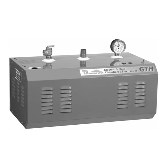
GTH
M
odels ranging from 6 kW to 36 kW :
2 4 0 V o l t s ( 1 p h a s e ) & 6 0 0 V o l t s ( 3 p h a s e s ) .
USE & CARE MANUAL
WITH INSTALLATION INSTRUCTIONS FOR THE CONTRACTOR
Your GTH Electric Boiler has been carefully assembled and factory tested to provide years
of trouble-free service. The following information and safety measures are provided to
enable proper installation, operation, and maintenance of this product.
It is imperative that all persons who are expected to install, operate or adjust this boiler
should read these instructions carefully.
Any questions regarding the operation, maintenance, service or warranty of this electric
boiler should be directed to the supplier.
When all installation steps have been completed, insert this installation manual in its original
envelope, and keep in a safe place (close to the boiler) for future reference.
THERMO 2000 INCORPORATED
Printed in Canada
Electric Boilers
revision : November 2005
Advertisement
Table of Contents

Related Manuals for THERMO 2000 GTH 6


Summary of Contents for THERMO 2000 GTH 6
- Page 1 When all installation steps have been completed, insert this installation manual in its original envelope, and keep in a safe place (close to the boiler) for future reference. THERMO 2000 INCORPORATED revision : November 2005 Printed in Canada...
- Page 2 Section 1: Dimensions & Specifications Table 1: Electric Ratings for 240 VAC (1 phase) Electric Boilers: Current Wires Fuse Model Total Heating with Elements Circulator GTH 6 25.0 34.0 2 X 3KW 1X 3KW GTH 8 33.3 42.3 1 X 5KW GTH 10 41.6 50.6...
- Page 3 J) Wall Brackets/ Supports mural K) Circulator wiring/ Alimentation pompe L) Thermostat wiring/ Connection thermostat M) ON/OFF switch/ Interrupteur ON/OFF N) Elements Compartments/ Compartiment des éléments 16 7/16" THERMO 2000 inc. DESSIN D'ATELIER GTH/ GENERAL DIMENSIONS GTH REV. SIZE DWG. NO. TH2-ATELIER...
-
Page 4: General Safety Precautions
General Safety Precautions Be sure to read and understand the entire Use & Care Manual before attempting to install or to operate this electric boiler. Pay particular attention to the following General Safety Precautions. Failure to follow these warnings could cause property damage, bodily injury or death. Should you have any problems understanding the instructions in this manual, STOP, and get help from a qualified installer or technician. - Page 5 Section 3: Installation The electric boiler must be located or protected WARNING so as not to be subject to physical damage, for example, by moving vehicles, area flooding, etc. The manufacturer’s warranty does not cover All models can be installed on combustible floors any damage or defect caused by installation, and in alcoves.
- Page 6 3.4.4 Piping system pressurization: Use only clean pipe for boiler water lines. Local expansion tank codes or regulations shall govern the exact type Pressure control devices within the system of material to be used. ensure that each component operates within minimum and maximum allowable pressures Insulate all pipes containing hot water, and maintain minimum pressure for all normal...
- Page 7 this precludes the use of air in direct contact with Second example: If the boiler water has a return the boiler water as a pressurization means. temperature of 120 °F and the boiler supply is at 140 °F, then the temperature drop is 20 °F Installation of manual or automatic air vent (=140 °F –...
- Page 8 BWTD Model high point in the system where it can be purged. GTH 6 It is generally accepted that if proper air control GTH 8 is provided to eliminate air and turbulence in the...
- Page 9 Zone valve zoning 3.5.2 600Vac models Connect the low voltage thermostat to the zone valve. Components must be wired to ensure that Line wiring must be from a 600 Volt ( 3 phase, only the zone valve corresponding to the zone 60 Hz) circuit protected by a properly sized calling for heat is actuated and that the circulator breaker.
- Page 10 3.8 CBE-EM DUAL ENERGY INSTALLATION In order to obtain a special rate from your electric utility for residential use, your GTH boiler can be hooked-up to an existing oil heater. Contact your electric utility to find out if your property is eligible for such rates and how to register for them.
- Page 11 Section 4: Operation SAFETY PRECAUTIONS lowest that satisfies the heating needs. Please refer to table 5 for more details. Before operating this boiler, be sure to read and follow these instructions, as well as the Each aquastat controls one stage (in the 240V warnings printed in this manual.
- Page 12 4.3 STARTUP PROCEDURE 1. Fill the boiler as described in section 4.1. 2. Set the boiler operating temperature as described in section 4.2. 3. Turn down all room thermostats under room temperature 4. Turn on the boiler power breakers and switch.
- Page 13 Section 5: Maintenance Properly maintained, your boiler will provide years of dependable, trouble free service. It is recommended It is recommended to perform a visual inspection of that a regular routine maintenance program be the boiler electrical compartment annually, during established and followed by the user.
- Page 14 10) T & P Gage/ Tridicateur L1 L2 N Raccordement de pompe GTH 600V/ Pump wiring GTH 600V Thermostat Relais/Relay RA89A GTH 240V THERMO 2000 inc. jumper Schéma d'installation général/ General installation Simple zone/ Single zone Pompe/Pump 120Vac Figure 14...
- Page 15 15) Thermostat/ Thermostat 8) Drain valve/ Valve drainage 9) Safety valve/ Valve de sécurité 10) T & P Gage/ Tridicateur L1 L2 N THERMO 2000 inc. GTH 240V Schéma d'installation général/ General installation Zonage de plinthes/ Valve zoning to baseboard...
- Page 16 7) Purge valve/ Robinet élimination d'air 8) Drain valve/ Valve drainage 9) Safety valve/ Valve de sécurité 10) T & P Gage/ Tridicateur T=105 F L1 L2 N THERMO 2000 inc. GTH 240V T=90 F Schéma d'installation général/ General installation Plancher chauffant direct/...
- Page 17 13) Return header/ Collecteur de retour 14) Radiant infloor piping/ Plancher chauffant 15) Thermostat/ Thermostat 16) Supply header/ Collecteur d'alimentation 17) Circuit balancing valve/ THERMO 2000 inc. T=85 F Valve de balancement GTH 240V 18) Indoor- Outdoor controller/ Conjtrôleur modulant Int.-Ext.
- Page 18 Figure 6 Diagramme électrique/ Wiri ng diagram Raccordement de pompe GTH 600V/ Wiring pump for GTH 600V Relais de pompe/pump relay Thermostat Relais/Relay RA89A jumper Pompe/Pump 120Vac Diagramme électrique/ Wiri ng diagram Raccordement de zone valves/ Wiring for zoned va lves system Thermostat Thermostat Thermostat...
- Page 19 OPTION Note 1: Bloc terminal (24 VAC) pour une installation avec le controleur bi-énergie Thermo 2000 modèle: "CBE-EM"/ Terminal block (24 VAC) for an installation with Thermo 2000 dual Voir note 1 energy controller model: "CBE-EM" Note 2: Couper le cavalier lorsque vous utilisez le controleur bi-énergie Thermo 2000 modèle: "CBE-EM"/...
- Page 20 Note 1: Bloc terminal (24 VAC) pour une installation avec le controleur bi-énergie Thermo 2000 modèle: "CBE-EM"/ Terminal block (24 VAC) for an installation with Thermo 2000 dual energy controller model: "CBE-EM" Note 2: Couper le cavalier lorsque vous utilisez le controleur bi-énergie Thermo 2000 modèle: "CBE-EM"/...
- Page 21 Note 1: Bloc terminal (24 VAC) pour une installation avec le controleur bi-énergie Thermo 2000 modèle: "CBE-EM"/ Terminal block (24 VAC) for an installation with Thermo 2000 dual energy controller model: "CBE-EM" Note 2: Couper le cavalier lorsque vous utilisez le controleur bi-énergie Thermo 2000 modèle: "CBE-EM"/...
- Page 22 Note 1: Bloc terminal (24 VAC) pour une installation avec le controleur bi-énergie Thermo 2000 modèle: "CBE-EM"/ Terminal block (24 VAC) for an installation with Thermo 2000 dual energy controller model: "CBE-EM" Note 2: Couper le cavalier lorsque vous utilisez le controleur Voir/see note 1 bi-énergie Thermo 2000 modèle: "CBE-EM"/...
- Page 23 Note 1: Bloc terminal (24 VAC) pour une installation avec le controleur bi-énergie Thermo 2000 modèle: "CBE-EM"/ Terminal block (24 VAC) for an installation with Thermo 2000 dual energy controller model: "CBE-EM" Note 2: Couper le cavalier lorsque vous utilisez le controleur Voir/see note 1 bi-énergie Thermo 2000 modèle: "CBE-EM"/...
- Page 24 Figure 12 Diagramme électrique/ Wiring diagram Contrôle Bi-énergy/ Dual control energy CBE-EM 120 Vac Transfo 24 Vac Lumière haut tarif/ High tarif light Relais GTH/ Sonde extérieur/ GTH Relay Bi-energie/ Dual energy Outdoor sensor Electrique/ Electric SPDT Mazout/ Oil Relais chaudière Relais/ Relay mazout/ Oil boiler Relay...
- Page 25 H H V1 V2 V3 T1T2 E1E 2 jumper/ cavalier Legeng/Légende: THERMO 2000 inc. 1) Main water supply / Alimentation d'eau 10) T & P Gage/ Tridicateur GTH 240V 2) Maintenance valve/ Valve d'entretien...
- Page 26 Brun Bleu Noir Legeng/Légende: 10) T & P Gage/ Tridicateur THERMO 2000 inc. 1) Main water supply / Alimentation d'eau 11) Automatic air vent/ Purgeur d'air GTH 240V 2) Maintenance valve/ Valve d'entretien 12) Flow check valve/ Clapet antigravité...
- Page 27 Figure 15 THERMO 2000 inc. GTH 6-10 KW 240V Liste des pièces/ Part list ITEM DESCRIPTION NUMERO ITEM DESCRIPTION NUMERO ITEM DESCRIPTION NUMERO Chaudière/ Boiler Isolation/ Insulation Porte fusible/ Fuse holder 1 pole class midjet Puit Haute-limite/ Hi-limit w ell...
- Page 28 Figure 16 THERMO 2000 inc. GTH 12-24 KW 240V Liste des pièces/ Part list ITEM DESCRIPTION NUMERO ITEM DESCRIPTION NUMERO ITEM DESCRIPTION NUMERO Chaudière/ Boiler Isolation/ Insulation Porte fusible/ Fuse holder 1 pole class midjet Puit Haute-limite/ Hi-limit w ell...
- Page 29 Figure 17 THERMO 2000 inc. GTH 27-33 KW 240V Liste des pièces/ Part list ITEM DESCRIPTION NUMERO ITEM DESCRIPTION NUMERO ITEM DESCRIPTION NUMERO Chaudière/ Boiler Isolation/ Insulation Porte fusible/ Fuse holder 1 pole class midjet Puit Haute-limite/ Hi-limit w ell...
- Page 30 Figure 18 THERMO 2000 inc. GTH 9-13 KW 600V Liste des pièces/ Part list ITEM DESCRIPTION NUMERO ITEM DESCRIPTION NUMERO ITEM DESCRIPTION NUMERO Chaudière/ Boiler Isolation/ Insulation Porte fusible/ Fuse holder 2 poles class cc Puit Haute-limite/ Hi-limit w ell...
- Page 31 Figure 19 THERMO 2000 inc. GTH 18-36 KW 600V Liste des pièces/ Part list ITEM DESCRIPTION NUMERO ITEM DESCRIPTION NUMERO ITEM DESCRIPTION NUMERO Chaudière/ Boiler Isolation/ Insulation Porte fusible/ Fuse holder 2 poles class cc Puit Haute-limite/ Hi-limit w ell...
- Page 32 Thermo 2000 Inc. warrants to the original purchaser that the GTH tank installed in a unit. This warranty limits its beneficiary’s rights. Nevertheless, the beneficiary may have commercial setting for ten years, the first (5) years in full and years six (6) through other rights, which vary from state to state.
Need help?
Do you have a question about the GTH 6 and is the answer not in the manual?
Questions and answers