Table of Contents
Advertisement
Electric Boilers
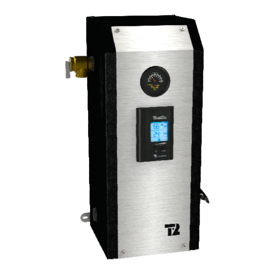
MINI ULTRA
Models from 3 kW to 12 kW : 208/240V single phase
INSTALLATION & OPERATING MANUAL
Your MINI ULTRA Electric Boiler has been carefully assembled and factory tested to provide
years of trouble-free service. The following information and safety measures are provided to
enable proper installation, operation, and maintenance of this product.
It is imperative that all persons who are expected to install, operate or adjust this boiler
should read these instructions carefully.
Any questions regarding the operation, maintenance, service or warranty of this electric
boiler should be directed to the supplier.
When all installation steps have been completed, keep this installation manual in a safe
place (close to the boiler) for future reference.
THERMO 2000 Inc.
Printed In Canada
Revision: May 2015
Advertisement
Table of Contents

Subscribe to Our Youtube Channel
Related Manuals for THERMO 2000 MINI ULTRA


Summary of Contents for THERMO 2000 MINI ULTRA
- Page 1 Models from 3 kW to 12 kW : 208/240V single phase INSTALLATION & OPERATING MANUAL Your MINI ULTRA Electric Boiler has been carefully assembled and factory tested to provide years of trouble-free service. The following information and safety measures are provided to enable proper installation, operation, and maintenance of this product.
-
Page 2: Table Of Contents
6.1.3 Annually ..........................18 6.2 REPLACEMENT PARTS ......................19 Section 7 : TROUBLESHOOTING ......................20 Table 4: Sensors resistance value vs real temperature..............21 MINI ULTRA LIMITED WARRANTY ....................22 MINI ULTRA ELECTRIC BOILERS Installation and operating manual (Revision: May 2015) - Page 3 Figure 9 : UltraSmart Controller Display ....................12 Figure 10 : UltraSmart Control Module ....................13 Figure 11 : Replacement Parts (Front view) ................... 19 Figure 12 : Replacement Parts (Top view) ..................... 19 MINI ULTRA ELECTRIC BOILERS Installation and operating manual (Revision: May 2015)
-
Page 4: Section 1: Technical Specifications
Figure 1 : Dimensions Some provinces or states, may require boilers built in conformity to ASME standards. If such models are required, model with an “H” suffix shall be used. MINI ULTRA ELECTRIC BOILERS Installation and operating manual (Revision: May 2015) -
Page 5: Section 2: Introduction
The manufacturer’s responsibility ceases upon delivery of goods to the carrier in good condition. Consignee must file any claims for damage, shortage in shipments, or non- delivery immediately against carrier. MINI ULTRA ELECTRIC BOILERS Installation and operating manual (Revision: May 2015) -
Page 6: Section 3 : Installation
All models can be installed directly on a combustible wall and into an alcove. The location must have sufficient ventilation to maintain an ambient temperature not exceeding 90F (32C). MINI ULTRA ELECTRIC BOILERS Installation and operating manual (Revision: May 2015) -
Page 7: Boiler Water Connections
Figure 3 &4 below shows typical connections of a MINI BTH boiler to a radiant floor and cast iron radiator heating systems. The location of the distribution system components may be different from what is represented. Figure 3 : Typical piping lay-out MINI ULTRA ELECTRIC BOILERS Installation and operating manual (Revision: May 2015) -
Page 8: Pressure Relief Valve
20F between their inlet and outlet can automatically be fed with water in the event of a pressure drop. The minimum pressure obtained when the system is cold is generally 12 psi (83kPa). MINI ULTRA ELECTRIC BOILERS Installation and operating manual (Revision: May 2015) -
Page 9: Drain Valve
Do not put a jumper between S1&S1 if the outdoor To do so, consult the boiler rating plate which will sensor is not used. indicate the amperage drawn by the boiler at full MINI ULTRA ELECTRIC BOILERS Installation and operating manual (Revision: May 2015) -
Page 10: Thermostat(S) And Pump(S) Connections
To do so, you will need relays as illustrated below. Boiler terminals P-P will not be used. Figure 5 : Zoning with Multiple pumps MINI ULTRA ELECTRIC BOILERS Installation and operating manual (Revision: May 2015) -
Page 11: Figure 7 : Wiring Diagram (3-9 Kw)
Figure 7 : Wiring diagram (3-9 KW Figure 8 : Wiring diagram (12 KW) MINI ULTRA ELECTRIC BOILERS Installation and operating manual (Revision: May 2015) -
Page 12: Section 4: Adjustments Of The Control Module
Piping system) Two operation modes are then offered: Fixed boiler temperature set point (the outdoor sensor shall not be installed) Outdoor reset Figure 9 : UltraSmart Controller Display MINI ULTRA ELECTRIC BOILERS Installation and operating manual (Revision: May 2015) -
Page 13: Operation Of The Interface
A rotation of the stages based on an equal time period of operation is provided. N.B. The supplied outdoor temperature sensor must be connected before applying the electrical power to the unit. MINI ULTRA ELECTRIC BOILERS Installation and operating manual (Revision: May 2015) -
Page 14: Purge Delay Of The Pump
This selection shall be selected on systems equipped with motorised fast closing time zone valves with in order to prevent noise from water hammering. MINI ULTRA ELECTRIC BOILERS Installation and operating manual (Revision: May 2015) -
Page 15: Adjustments Of The Target Temperature By The User
“0” offset value from the original settings. When the + or- buttons are pressed again the offset value will change up to a value of +/- 10°F MINI ULTRA ELECTRIC BOILERS Installation and operating manual (Revision: May 2015) -
Page 16: Boost System Operation
“Setting procedure” would be too low for the heating system on which the unit is applied. This boiler target could simply be gradually increased by pressing the + button or MINI ULTRA ELECTRIC BOILERS Installation and operating manual (Revision: May 2015) -
Page 17: Section 5: Start Up Operation
The heating elements shall gradually stop as the temperature increases and gets near the target temperature. MINI ULTRA ELECTRIC BOILERS Installation and operating manual (Revision: May 2015) -
Page 18: Section 6: Maintenance
Required corrections should be made as soon as possible. Parts used for replacement should be the same as the original equipment. MINI ULTRA ELECTRIC BOILERS Installation and operating manual (Revision: May 2015) -
Page 19: Replacement Parts
ZEL200-L6C732 Figure 12 : Replacement Parts (Top view) ** When replacing a heating element, make sure to install it in the same orientation it was installed at the factory. MINI ULTRA ELECTRIC BOILERS Installation and operating manual (Revision: May 2015) -
Page 20: Section 7 : Troubleshooting
Open the front and left side panel of supply voltage to the boiler. the boiler the boiler. Check the components and electric wires for indications of overheating. MINI ULTRA ELECTRIC BOILERS Installation and operating manual (Revision: May 2015) -
Page 21: Table 4: Sensors Resistance Value Vs Real Temperature
1,172 196,358 22,763 4,184 1,073 165,18 19,9 3,76 139,402 17,436 3,383 118,018 15,311 3,05 100,221 13,474 2,754 85,362 11,883 2,49 72,918 10,501 2,255 62,465 9,299 2,045 53,658 8,25 1,857 MINI ULTRA ELECTRIC BOILERS Installation and operating manual (Revision: May 2015) -
Page 22: Mini Ultra Limited Warranty
This warranty All MINI ULTRA components & parts are warranted for a period of limits its beneficiary’s rights. Nevertheless, the beneficiary may two (2) years against defects due to defective material or have other rights, which vary from jurisdiction to jurisdiction.
Need help?
Do you have a question about the MINI ULTRA and is the answer not in the manual?
Questions and answers