
Related Manuals for Mosa GE 15 PSX


Summary of Contents for Mosa GE 15 PSX
- Page 1 GE 15 PSX GE 20 PSX 0 3 1 1 842509003 - GB USE AND MAINTENANCE MANUAL SPARE PARTS CATALOG © MOSA 03/03/11 84250M00 Preparato da UPT Approvato da DITE...
-
Page 2: Front Panel
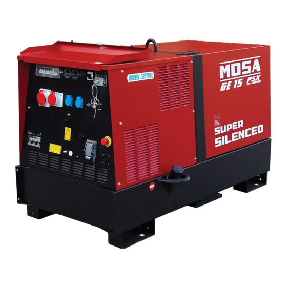
DESCRIPTION OF THE MACHINE GE 15 PSX GE 20 PSX REV.0-03/11 The generating set is a unit which transforms the mechanical energy, generated by endothermic engine, into electric energy, through an alternator. The unit is composed of a structured base which includes a tank, an engine/alternator unit fixed on the base by elastic dampers, a roll-bar, with hook for an easy and sure lifting, a chest hinged to the roll-bar for a quick access to the engine and to the air filter. - Page 3 · Competent support in the solution of problems; ofthe International Certification Network IQNet, · Information and training in the correct applicatio- awarded the official approval to MOSA after an- nand use of the products to assure the security examination of its operations at the head office ofthe operator and protect the environment;...
- Page 4 INDEX GE 15 PSX GE 20 PSX REV.0-03/11 DESCRIPTION OF THE MACHINE M 01 QUALITY SYSTEM M 1.01 COPYRIGHT M 1.1 NOTES M 1.4 CE MARK M 1.4.1 DECLARATION OF CONFORMITY M 1.5 TECHNICAL DATA M 2 - 2.1 SYMBOLS AND SAFETY PRECAUTIONS M 2.5 -….
- Page 5 We advise you to pay attention to the pages concerning the security (see page M1.1). All rights are reserved to said Company. © It is a property logo of MOSA division of B.C.S. S.p.A. All other possible logos contained in the documentation are registered by the respective owners.
-
Page 6: Notes About The Manual
(fastenings, holes, electric or mechanical devices, incorrect maintenance. The manual is for qualified others..) if not duly authorized in writing by MOSA: personnel, who knows the rules: about safety and the responsibility coming from any potential... - Page 7 CE MARK REV.5-03/11 Any of our product is labelled with CE marking attesting its conformity to appliable directives and also the fulfillment of safety requirements of the product itself; the list of these directives is part of the declaration of conformity included in any machine standard equipment. Here below the adopted symbol: CE marking is clearly readable and unerasable and it can be either part of the data-plate.
-
Page 8: Dichiarazione Di Conformita
Dichiarazione conformità Konformitätserklärung Declaration of conformity Declaración de conformidad 1.4.1 Déclaration de conformité REV.0-06/10 BCS S.p.A. Stabilimento di Cusago, 20090 (MI) - Italia V.le Europa 59 Sede legale: Tel.: +39 02 903521 Via Marradi 1 Fax: +39 02 90390466 20123 Milano - Italia DICHIARAZIONE DI CONFORMITA' Déclaration de Conformité... - Page 9 Technical data GE 15 PSX GE 20 PSX REV.0-03/11 Technical data GE 15 PSX GE 20 PSX GENERATOR *Stand-by three-phase power 15 kVA (12 kW) / 400 V / 21.6 A 22 kVA (17.6 kW) / 400 V / 31.8 A *PRP three-phase power 14 kVA (11.2 kW) / 400 V / 20.2 A...
-
Page 10: Symbols In This Manual
SYMBOLS AND SAFETY PRECAUTIONS GE_, MS_, TS_ © MOSA 1.0-11/99 SYMBOLS IN THIS MANUAL SAFETY PRECAUTIONS DANGEROUS The symbols used in this manual are designed to call your attention to important aspects of the operation of the machine as well as potential hazards and dangers This heading warns of an immediate danger for persons for persons and things. -
Page 11: Symbols And Safety Precautions
SYMBOLS AND SAFETY PRECAUTIONS © MOSA REV.2-06/10 SYMBOLS PROHIBITIONS No harm for persons Use only with safety clothing - STOP - Read absolutely and be duly attentive It is compulsory to use the personal protection means given in equip- ment. - Page 12 INSTALLATION AND ADVICE BEFORE USE GE_, MS_, TS_ © MOSA 1.0-06/00 The installation and the general advice concerning the operations, are finalized to the correct use of the ma- chine, in the place where it is used as generator group and/or welder.
-
Page 13: Gasoline Engines
INSTALLATION AND ADVICE © MOSA REV.1-06/07 Check that the air gets changed completely and the hot INSTALLATION AND ADVICE BEFORE USE air sent out does not come back inside the set so as to cause a dangerous increase of the temperature. - Page 14 Installazione e dimensioni Luftzirkulation und abmessungen Installation and dimensions Instalación y dimensiones GE 15 PSX Installation et dimensions GE 20 PSX REV.0-03/11...
- Page 15 Installazione e dimensioni Luftzirkulation und abmessungen Installation and dimensions Instalación y dimensiones GE 15 PSX 2.7.1 Installation et dimensions GE 20 PSX REV.0-03/11...
- Page 16 UNPACKING © MOSA REV.1-02/04 NOTE + Be sure that the lifting devices are: correctly mounted, adequate for the weight of the machine with it’s pack- aging, and conforms to local rules and regulations. When receiving the goods make sure that the product...
-
Page 17: Transport And Displacements Covered Units
TRANSPORT AND DISPLACEMENTS COVERED UNITS © MOSA REV.1-06/10 NOTE Transportation must always take place with the engine off, electrical cables and starting battery disconnected and fuel tank empty. Be sure that the lifting devices are: correctly mounted, adequate for the weight of the machine with it’s packaging, and conform to local rules and regulations. - Page 18 CTL22 ASSEMBLY REV.2-05/09 ATTENZIONE The CTL accessory cannot be removed from the machine and used separately (actioned manually or following vehicles) for the transport of loads or anyway for used different from the machine movements. TRAILERS The machines provided for assembling the accessory (slow towing trolley) can be towed up to a maximum speed of 40 Kms/hour on asphalted surfaces.
- Page 19 Avoid accidentally spilling fuel. Clean RECOMMENDED OIL any eventual leaks before starting up MOSA recommends selecting AGIP engine oil. motor. Refer to the label on the motor for the recommended products. Refill the tank with good quality diesel fuel, such as automobile type diesel fuel, for example.
-
Page 20: Cooling Liquid
Set-up for operation Water cooled systems REV.1-02/11 GROUNDING CONNECTION COOLING LIQUID ATTENTION The grounding connection to an earthed installation is obligatory for all models equipped with a diffe- Do not remove the radiator tap with the rential switch (circuit breaker). In these groups the motor in operation or still hot, as the generator star point is generally connected to the liquid coolant may spurt out and cause... - Page 21 START AND STOP (EP6) REV.0-02/06 Check daily Connect the EAS to unit. The EAS controls the starting as well as the stop of the engine. Follow attentively the instructions reported in the EAS manual. In these conditions the EP6 has NOTE the only function to measure the electric values, hour-meter, etc.
- Page 22 CONTROLS LEGENDE © MOSA REV.1-10/07 Hydraulic oil level light Button indicating light 30 l/1' PTO HI Battery voltmeter Welding socket ( + ) Engine control unit EP2 Remote control socket Welding socket ( - ) E.A.S. connector Button indicating light 20 l/1' PTO HI...
- Page 23 Comandi Bedienelemente Controls Mandos GE 15 PSX Commandes GE 20 PSX REV.0-03/11 GE 15 PSX GE 20 PSX...
- Page 24 Components of frontal panel GE 15 PSX GE 20 PSX REV.0-03/11 Thermal-magnetic circuit breaker General switch for the gen-set. It protects both gen-set and related electrical circuit from over current /short circuit. Ground fault interrupter (30 mA) Device for protection against not-direct contacts for TN and TT...
- Page 25 Using the generator © MOSA REV.2-06/10 (PRP), STAND-BY POWER established by ISO 8528-1 WARNING and 3046/1 Norms, and their definitions are listed in the manual’s TECHNICAL SPECIFICATIONS page. It is absolutely forbidden to connect the unit to the public mains and/or another electrical + During the use of the electricity-generating group NE- power source .
- Page 26 Using the generator © MOSA REV.1-09/05 In some motors or for special requirements the speed - The maximum power which can be drawn between regulator is electronic; in these cases, precision under Neutral and Phase (start connection) is generally 1/3 static operating conditions attains ±0.25%, and the...
-
Page 27: Differential Switch
Using the generator © MOSA REV.1-09/05 DIFFERENTIAL SWITCH USAGE WITH EAS AUTOMATIC START-UP PANEL The differential switch or differential relay guarantee The electricity-generating group in combination with the protection against indirect contacts due to malfunction EAS automatic start-up panel forms a unit for distributing currents towards the ground. - Page 28 TCM 35 REMOTE CONTROL 38.6 © MOSA 1.0-03/06 MAKE SURE ➔ The selector LOCAL START/REMOTE START (I6) of the generating set must be switched on LOCALSTART. ➔ Put the selector „switch board (N7)“ on ON. The coupling of the TCM 35 with the generating set, ready for remot starting, permits to work far from the set itself.
- Page 29 PROTECTIONS EP6 ENGINE PROTECTION 39.12 REV.1-03/11 EP6 user manual Once in AUTO, the EP6 waits for a REMOTE 1.0 Introduction M39.12 START activation (see section 7.0). 2.0 Operating Mode selection M39.12 In case of an Automatic Periodic Test (A.P.T.), 2.1 AUTO operating mode M39.12 the display will show the message [tESt].
-
Page 30: Operating Messages
PROTECTIONS EP6 ENGINE PROTECTION 39.12. REV.1-03/11 5.0 LEDs for visual indication 4.0 ALARM messages The EP6 features two LEDs (see section 10.0) to The alarms are displayed by means of messages. indicate the following conditions: In case of alarm consult your Generating Set manu- facturer. - Page 31 PROTECTIONS EP6 ENGINE PROTECTION 39.12. REV.0-10/05 Display Parameter [Default] [P.0] Remote Start Delay Timing (Input #7) [ 1"] Range: 1-59 secs or 1-15 mins Seconds or minutes of continuous REMOTE START command to initiate the auto- matic engine start (see section 7.0 and [P20] in this section). [P.1] Remote Stop Delay Timing (Input #7) [ 1"] Range: 1-59 secs or 1-15 mins...
- Page 32 PROTECTIONS EP6 ENGINE PROTECTION 39.12. REV.1-03/11 Range: 2-99 secs. Duration of the Stop cycle. [P.17] Alarm Output Timing [ 1'] [inh.]-59 secs 1-15 mins and [cont]. Time-out of the alarm output. The code [cont] disables the time-out, and the alarm remains energized until the OFF operating mode is selected.
- Page 33 PROTECTIONS EP6 ENGINE PROTECTION 39.12. REV.1-03/11 7.0 REMOTE START - wait for the desired start time (external clock re- The EP6 features REMOTE START only in AUTO ference) operating mode. - apply the power supply to the EP6 (consult your To operate the REMOTE START, follow the instruc- genset supplier) tions.
-
Page 34: Troubleshooting
Diesel engine 40.2 Troubleshooting REV.3-07/06 Problem Possible cause Solution ENGINE The motor does not start up 1) Start-up switch (I6) (where it is assembled) in 1) Check position incorrect position 2) Emergency button (L5) pressed 2) Unblock 3) Preheating (where it is assembled) 3) Lacking or insufficient preheating phase for sparkplugs. - Page 35 Troubleshooting Diesel engine 40.2. REV.4-03/11 Problem Possible cause Solution GENERATOR Absence of output voltage Voltage switch in position 0 Check position Voltage switch faulty Check connections and working of the switch, repair or replace Protection tripped due to overload Check the load connected and diminish Differential protection device tripped.
-
Page 36: Electrical Panels
STRENUOUS OPERATING CONDITIONS and mechanic components consumed in normal use, by Under extreme operating conditions (frequent stops the Assistance Authorized Center as well as by MOSA. and starts, dusty environment, cold weather,extended periods of no load operation, fuel with over 0.5% sulphur The replacement of tires (for machines equipped with content) do maintenance more frequently. -
Page 37: Maintenance
MAINTENANCE 43.1 © MOSA 1.0-09/05 ATTENTION Maintenance operations on the electricity-generating group prearranged for automatic operation must be ■ carried out with the panel in RESET mode. Maintenance operations on the installation’s electrical panels must be carried out in complete safety by cutting ■... -
Page 38: Gasoline Engine
STORAGE © MOSA REV.0-06/07 In case the machine should not be used for more than 30 days, make sure that the room in which it is stored presents a suitable shelter from heat sources, weather changes or anything which can cause rust, corrosion or damages to the machine. - Page 39 CUST OFF © MOSA REV.0-06/07 Have qualified personnel disassemble the In case of necessity for first aid and fire prevention, machine and dispose of the parts, including the see page M2.5. oil, fuel, etc., in a correct manner when it is to be taken out of service.
-
Page 40: Electrical System Legende
ELECTRICAL SYSTEM LEGENDE © MOSA REV.7-10/09 : Alternator : Insulation moitoring : Commutator/switch : Wire connection unit : E.A.S. connector : Key switch, on/off : Capacitor : E.A.S. PCB : QEA control unit : G.F.I. : Booster socket : Connector, PAC... - Page 41 Schema elettrico Stromlaufplan Electric diagram Esquema eléctrique GE 15 PSX 61.1 Schema electriques GE 20 PSX REV.0-03/11...
- Page 42 Schema elettrico Stromlaufplan Electric diagram Esquema eléctrique GE 15 PSX 61.2 Schema electriques REV.0-03/11...
- Page 43 Schema elettrico Stromlaufplan Electric diagram Esquema eléctrique GE 20 PSX 61.3 Schema electriques REV.0-03/11...
- Page 44 GE 15 - 20 PSX Schema elettrico Stromlaufplan Electric diagram Esquema eléctrique GE 35 PS - PSX 61.4 GE 55 PS - PMS Schema electriques REV.0-03/06...
-
Page 45: Spare Parts List
© MOSA 1.0-03/00 MOSA guarantees that any request for spare parts will be satisfied. To keep the machine in full working order, when replacement of MOSA spare parts is required, always ask for genuine parts only. The requested data are to be found on the data plate located on the machine structure, quite visible and easy to consult. - Page 46 Ricambi Ersatzteile Spare parts Tabla de recambios GE 15 PSX Piéces de rechanges GE 20 PSX REV.0-03/11...
- Page 47 Tavola ricambi Ersatzteile Spare parts table Tabla de recambios GE 15 PSX Table piéces de rechange GE 20 PSX REV.0-03/11 Pos. Cod. Descr. Note M842503100 ALTERNATORE LINZ GE 15 M842143100 ALT. STAMFORD GE 20 M841562071 GUARNIZIONE M841562212 TUBO SCARICO OLIO...
- Page 48 Ricambi Ersatzteile Spare parts Tabla de recambios GE 15 PSX Piéces de rechanges GE 20 PSX REV.0-03/11...
- Page 49 Tavola ricambi Ersatzteile Spare parts table Tabla de recambios GE 15 PSX 10.1 Table piéces de rechange GE 20 PSX REV.0-03/11 Pos. Cod. Descr. Note M317807130 COPERCHIO PROTEZIONE I.D. / COVER PROTECTION M842100094 MG5 KIT TERMO/MANOMETRO / MG5 KIT TERMO/MANOMETRO (SR)
- Page 50 Ricambi Ersatzteile Spare parts Tabla de recambios GE 15 PSX Piéces de rechanges GE 20 PSX REV.0-03/11...
- Page 51 Tavola ricambi Ersatzteile Spare parts table Tabla de recambios GE 15 PSX 11.1 Table piéces de rechange GE 20 PSX REV.0-03/11 Pos. Cod. Descr. Note M764407015 COPERCHIO SCATOLA ELETTRICA M764408290 PARATIA SUPERIORE ALTERNATORE M764401100 ROLL-BAR M105112270 GUARNIZIONE (L=MT.1) M308102207 TUBO GOMMA (L=MT.1) M107301890 TUBO SFIATO (L=MT.1)
- Page 52 Ricambi Ersatzteile Spare parts Tabla de recambios GE 15 PSX Piéces de rechanges GE 20 PSX REV.0-03/11...
-
Page 53: Rear Cover
Tavola ricambi Ersatzteile Spare parts table Tabla de recambios GE 15 PSX 12.1 Table piéces de rechange GE 20 PSX REV.0-03/11 Pos. Cod. Descr. Note M102302280 GUARNIZIONE (L=MT.1) qm (*) M105112270 GUARNIZIONE (L=MT.1) qm (*) M764408035 CARENATURA POSTERIORE M744508140 CERNIERA PER FIANCATA... - Page 54 CTL 22 305200140 © MOSA REV.2-05/09 Pos. Cod. Descr. Descr. Note 0000344050141 GR.TIMONE,PIEDE x TRAINO LENTO KIT SITE TOW Da/from REV.2-05/09 Del.178/08-15/10/08 0000225100141 GR.TIMONE,PIEDE x TRAINO LENTO KIT SITE TOW Da/from REV.1-02/07 Del.09/07-.26/01/07 Fino a/up to REV.1-02/07 Del.178/08-15/10/08 0000305200141 GR.TIMONE,PIEDE x TRAINO LENTO KIT SITE TOW Fino a/up to REV.
- Page 55 TCM35 930350000 © MOSA 1.0-06/06 Pos. Rev. Cod. Descr. Descr. 930357219 INTERRUTTORE 2P 16A INTERRUPTER 2P 16A 930359913 SCATOLA COMPLETA CASE, COMPL. 930357227 LAMPADA 24V WARNING LIGHT 24V 930357231 PORTALAMPADA SPIA ROSSA WARNING LIGHT HOLDER 93035C060 GR. CAVI TCM TCM CABLE KIT...
Need help?
Do you have a question about the GE 15 PSX and is the answer not in the manual?
Questions and answers