
Related Manuals for PICARRO G2207-i


Summary of Contents for PICARRO G2207-i
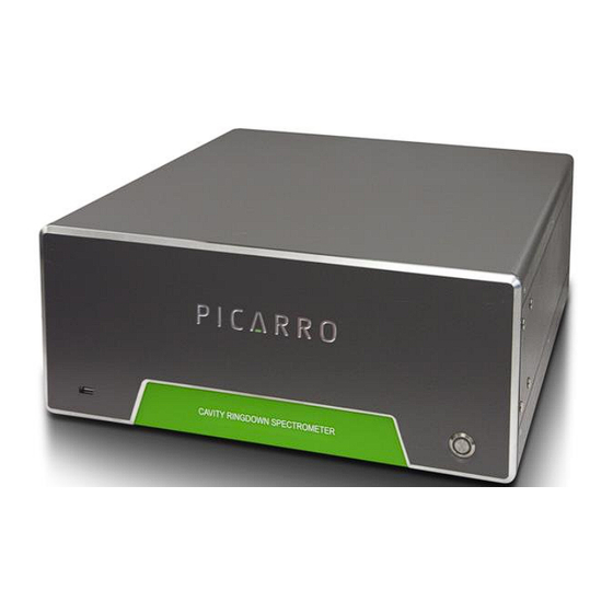
- Page 1 G2207-i Analyzer for and O in Air User Manual Picarro Inc. 3105 Patrick Henry Drive Santa Clara, CA 95054, USA Phone: +1 408 962 3944 www.picarro.com Document Number 40-0034 Rev. B...
- Page 2 NOTICES DISCLAIMER AND RESERVATION OF RIGHTS Picarro has prepared this manual solely for the information and use by its customers as a guide for the selection, installation, operation, and maintenance of the products described.
-
Page 3: Contact Information
+31 85 888 1650 Customer Service: Email: orders@picarro.com Phone: +1 408 962 3992 © 2020 Picarro, Inc. All rights reserved. 3105 Patrick Henry Drive Santa Clara, California, 95054 USA Phone 408.962.3900 • Fax 408.962.3200 www.picarro.com G2207-i User Manual P/N 40-0034-Rev B... -
Page 4: Table Of Contents
Setting Up a Monitor, Keyboard, and Mouse ........26 ANALYZER BASIC OPERATION ............... 28 Startup Procedure ................28 Desktop Icons and Folders ..............29 Shutdown Procedure ................. 31 In case of an Electrical Power Outage ..........32 P/N 40-0034-Rev B G2207-i User Manual... - Page 5 13. SERVICE AND MAINTENANCE ..............67 13.1 Particulate Filter Replacement ............67 13.2 Cleaning .................... 71 14. TRANSPORTATION AND STORAGE ............72 15. LIMITED WARRANTY ................73 REMOTE DATA ACCESS ............75 A.1 Picarro Serial Communication ............... 75 G2207-i User Manual P/N 40-0034-Rev B...
- Page 6 C.3 Setting Up Solenoid Valves ..............92 C.4 Setting Up Rotary Selector Valve ............93 C.5 Valve Sequencer Software ..............94 C.6 Configuring a Valve Sequence ............. 95 C.7 Loading and Running a Saved Sequence ..........95 P/N 40-0034-Rev B G2207-i User Manual...
-
Page 7: Introduction To Technology
In the cavity, a series of mirrors reflects the infrared light through the sample, increasing the path length. For a Picarro cavity of only 25 cm in length, the effective path length of the cavity can be over 20 kilometers. -
Page 8: Relating Ring-Down Time To Absorption Intensity
Determining absorption intensity at a specific wavelength requires comparing the ring-down time of an empty cavity to the ring-down time of a cavity that contains gas. A cavity can be empty if it contains no gas; it will P/N 40-0034-Rev B G2207-i User Manual... -
Page 9: Converting Absorption Intensity To Concentration
Picarro instruments gather measurements from an “empty” cavity by switching the light to wavelengths that are not absorbed by the target molecules. -
Page 10: Spectral Precision And High Sensitivity Measurements
Picarro analyzers calculate the baseline underneath a poorly resolved peak by modeling the absorption peaks from other surrounding molecules and subtracting contributions from neighboring peaks to the absorption intensity. - Page 11 For precise pressure control, the cavity pressure is monitored using a high- linearity pressure transducer. The system computer uses this pressure data in a feedback loop to control proportional valves that adjust the inlet and outlet gas flow of the cavity. G2207-i User Manual P/N 40-0034-Rev B...
-
Page 12: Conventions
CAUTION alerts you of a potential danger to equipment or to the user. CAUTION WARNING indicates an imminent danger to the user. WARNING REMINDER is a helpful hint to procedures listed in the text. REMINDER P/N 40-0034-Rev B G2207-i User Manual... -
Page 13: Acronyms
Acronym Definition CRDS Cavity Ring-Down Spectroscopy Graphical User Interface centimeters millimeters ” (as in 1/4”) Inches Oxygen Ammonia Water Hotbox Warm box Parts Per Million Parts Per Billion ‰ per mil °C degrees Celsius G2207-i User Manual P/N 40-0034-Rev B... -
Page 14: Safety
4. SAFETY General Safety CDRH Certification This Picarro Analyzer complies with 21 CFR Chapter 1, sub-chapter J, and is classified as a Class 1 laser system when all panels and covers are on. CE Certification This Picarro Analyzer complies with the European standards and the instrument is affixed with a CE label. -
Page 15: Laser Safety
WARNING laser safe service area using appropriate laser-safety glasses. The following Laser Safety Label is affixed to the inside of the analyzer: G2207-i User Manual P/N 40-0034-Rev B... - Page 16 Figure 4: Laser Safety Label Use of controls or adjustments or performance of procedures other than those specified herein may result in hazardous radiation exposure. WARNING P/N 40-0034-Rev B G2207-i User Manual...
-
Page 17: Unpacking The Analyzer
5. UNPACKING THE ANALYZER Inspect the Shipping Boxes Picarro products are inspected and tested before leaving the factory. Their packing containers have been designed to keep the equipment safe from damage during transit. Inspect the condition of the boxes upon arrival. The larger box includes the analyzer and most of the accessories. - Page 18 For External Solenoid Valves Nut (1) and For connecting input line to analyzer INPUT Ferrules (2) Document Includes this manual, certificate of compliance, Packet (1) and Windows License. USB Flash Drive Contains backup software. P/N 40-0034-Rev B G2207-i User Manual...
- Page 19 A power cable with connectors appropriate to Cable (1) your country is provided. The pump automatically adjusts to local voltage. Vacuum Hose (1) Hose to connect the pump to the analyzer. Pump Manual (1) Detailed instructions for pump. G2207-i User Manual P/N 40-0034-Rev B...
-
Page 20: Analyzer Overview
6. ANALYZER OVERVIEW Intended Use and The G2207-i analyzer measures concentrations of O O in air using Picarro’s patented Cavity Ring-Down Spectroscopy (CRDS). The analyzer can be deployed for air monitoring applications in a lab or in the field, and ... -
Page 21: Analyzer Specifications
Steady-state Power 120 W (Analyzer), 150 W (Pump) Steady-state operation Mains Supply Voltage ±10% of the nominal voltage Fluctuation Minimum Rated Circuit 10 A @115 VAC Amperage 5 A @230 VAC Liquid Ingress Protection None G2207-i User Manual P/N 40-0034-Rev B... -
Page 22: Installation
7. INSTALLATION This section describes the setup and installation of the Picarro Analyzer. Please read and understand this section thoroughly before proceeding with the installation. Using this analyzer in a manner not specified by Picarro may result in damage to the analyzer and render it unsafe to operate. - Page 23 There should be 4” (10cm) of clearance in the front and back of the analyzer. Thermal Description Specifications 10 C 35 C Ambient Operating Worst-case environmental Temperature limits (unless otherwise specified) G2207-i User Manual P/N 40-0034-Rev B...
-
Page 24: Analyzer And Vacuum Setup
7. Connect the analyzer to a power source using the supplied AC power cable. Use the AC power cables supplied with the analyzer or a similarly rated cable. Check with Picarro technical support if you have questions about power cable replacement. An inadequately rated CAUTION power cable can result in equipment damage. -
Page 25: Connecting To The Analyzer Inlet
When using compressed gases, follow all appropriate safety conventions, including use of eye protection, physical restraint of cylinders, etc. WARNING Making a New Connection: When using new tubing, follow these steps. 1. Place the two ferrules inside the nut as shown. G2207-i User Manual P/N 40-0034-Rev B... -
Page 26: Setting Up A Monitor, Keyboard, And Mouse
2. Connect a mouse to one of the available USB ports. 3. Connect a monitor to one of the monitor ports. The analyzer will detect the connection and adjust the resolution to match the monitor. P/N 40-0034-Rev B G2207-i User Manual... - Page 27 4. Connect the monitor to a power source. 5. Turn on power to the monitor. G2207-i User Manual P/N 40-0034-Rev B...
-
Page 28: Analyzer Basic Operation
NOTE appropriate items until actual data is being reported in the graph. This is typically less than 30 minutes, but depending on ambient temperature, the analyzer can take up to 1 hour to stabilize. P/N 40-0034-Rev B G2207-i User Manual... -
Page 29: Desktop Icons And Folders
3. Picarro Mode Switcher: When clicked, you will be led to a window that will allow you to switch between various measurement modes. Most analyzer models are configured for one mode and may not include the Mode Switcher. - Page 30 Figure 8: Picarro Mode Switcher 4. Picarro Controller: When clicked, you will be led to a useful diagnostic panel allowing the user to see the analyzer’s internal temperatures, pressure, and spectroscopy in real time. This program has user-accessible functions, but it cannot change anything related to analyzer functionality.
-
Page 31: Shutdown Procedure
A flow of clean, relatively dry gas should always be directed to the instrument for several minutes prior to shutting down. Trapping a high-moisture content gas sample in the cavity can cause condensation damage to the mirrors as the instrument cools from CAUTION its operating temperature. G2207-i User Manual P/N 40-0034-Rev B... -
Page 32: In Case Of An Electrical Power Outage
If the power to the analyzer is cut-off for any reason, the analyzer will cease operation. However, when the power is reapplied, the analyzer will restart automatically. The Picarro software tools will also properly close out previous files and open new files for data collection so that previously collected data, instrument diagnostics, and other parameters recorded up to the time of power outage are retained. - Page 33 If short power outages will be a routine occurrence in your operating environment, Picarro recommends the use of an uninterrupted power supply to prevent damaging the hardware or software. G2207-i User Manual P/N 40-0034-Rev B...
-
Page 34: List Of Gui Functions
9. LIST OF GUI FUNCTIONS GUI Overview The features of the Picarro analyzer GUI are identified in Figure 11 and described in the following sections. Figure Layout of G2207-i Analyzer Settings, Tools, and Help Menus Settings Menu Left clicking on the Settings menu pulls down a menu that has one entry ‘Change GUI Mode from Standard to Service.’... -
Page 35: Alarm Panel
Tools Menu This menu item has three entries: 1. User Calibration: Opens the user calibration window (default password is “picarro”). The password can be reset in the QuickGui.ini file in the instrument directory: “C:\Picarro\G2000\AppConfig \Config\QuickGUI\” under the section: [Authorization] UserCalPassword = Picarro Show/Hide Valve 2. -
Page 36: Instrument Status
(i.e., if a new data log has not been started using the Start /Stop New Data Log Button). A new file will be generated at midnight, which will be saved to the same location as the original log file. P/N 40-0034-Rev B G2207-i User Manual... -
Page 37: Data Window
“sensors” is selected, the analyzer’s optical cavity pressure or temperature can be viewed as well as the nominal ambient temperature of the analyzer (“DAS temp”) and the temperature of the analyzer’s electronics chamber, indicated as “warm chamber temp.” G2207-i User Manual P/N 40-0034-Rev B... - Page 38 This buffer is empty upon instrument startup, and can also be emptied by pressing the reset data buffer button in the lower-right-hand corner of the GUI. P/N 40-0034-Rev B G2207-i User Manual...
- Page 39 Window. Changing the Data Key modifies the Digital Readout as well as the Data Window view. If the ‘Show Statistics’ entry is enabled in the ‘View’ menu, the mean, standard deviation and slope of the data in the graph are G2207-i User Manual P/N 40-0034-Rev B...
-
Page 40: Status Log Window
The duration of this step can range from 5 to 60 minutes, depending on the ambient temperature and how much time has elapsed since the last startup. P/N 40-0034-Rev B G2207-i User Manual... - Page 41 3. Pressure Stabilizing/Locked The valve control system begins to allow flow through the analyzer and stabilizes the pressure inside the cavity. 4. Measuring This is the normal mode of operation after startup has completed. G2207-i User Manual P/N 40-0034-Rev B...
-
Page 42: File Management
After each data file has been closed (every 15 minutes) it is moved to an archive directory, and a new file is started in the original location. The archive directory is C:\Picarro\G2000\Log\Archive\ and has subdirectories DataLog_Mailbox, DataLog_Private and DataLog_EventLogs with files arranged by year\month\day\hour. - Page 43 For more information about how to include various columns of data from the DataLog_Private in the C:\UserData DataLog files, please contact Picarro. The current data file can be found in C:\Picarro\G2000\Log\DataLogger\. Within this directory, there are subdirectories for DataLog_Private, DataLog_User, and DataLog_User_Sync. Similarly, the archive directory has subdirectories arranged by file type.
-
Page 44: File Archival And Automatic Deletion Of Old Files
The analyzer can automatically compress (zip) and archive old files as mentioned above. This operation is controlled by the .ini file: C:\Picarro\G2000\ AppConfig\Config\Archiver\Archiver.ini. For each file type, there are various items along with some recommended default settings which may vary by file type: Directory = C:/UserData/DataLog_Sync Optionally specifies which directory to find files to the archive. - Page 45 Specifies which directory to look in for files to delete. extension = data Specifies which files having what extension are to be deleted. If empty, it deletes all files. delete_time_hrs = 48 Specifies how long to keep files prior to deletion. G2207-i User Manual P/N 40-0034-Rev B...
-
Page 46: Set Up Tool
10.3 Set Up Tool In the desktop folder called Picarro Utilities, the Setup Tool can be launched by double-clicking on its icon. The tool allows the user to configure data file saving details, including which data elements are written to data files, digital data output (via serial port or TCP/IP), remote data delivery (via email), and general GUI properties. - Page 47 Make sure there are no COM port conflicts before clicking “Apply.” After making the appropriate edits, click “Apply” to put changes into effect and then “Exit” to close the window. Figure 22: Serial/Socket Port Setup Window G2207-i User Manual P/N 40-0034-Rev B...
- Page 48 • Data Directory: Location of the data you want email. After making the appropriate edits, click “Apply” to put changes into effect and then “Exit” to close the window. Figure 23: Data Delivery Setup Window P/N 40-0034-Rev B G2207-i User Manual...
- Page 49 3. Click “Apply” to put changes into effect and then “Exit” to close the window. You should now be able to access the “Show/Hide Valve Sequencer GUI” menu from the main GUI under “Tools” Figure 24: GUI Properties Window G2207-i User Manual P/N 40-0034-Rev B...
- Page 50 COM port/TCP (specified in the Port Manager tab). Two types of data can be specified here: Datalog_User & DataLog_User_Sync. After making the appropriate edits, click “Apply” to put changes into effect and then “Exit” to close the window. Figure 25: Command Interface Window P/N 40-0034-Rev B G2207-i User Manual...
- Page 51 Data Streaming outputs data continuously, whereas the Command Interface needs commands to prompt data output. After making the appropriate edits, click “Apply” to put changes into effect and then “Exit” to close the window. Figure 26: Data Streaming Window G2207-i User Manual P/N 40-0034-Rev B...
-
Page 52: Electrical Interface
Customizing Analog Output Channels The Picarro analyzer may be optionally configured with an Electrical Interface Card (EIC) that provides up to 8 analog signals available to the user for monitoring various measurements results and analyzer parameters. Electrical Interface The Electrical Interface tab allows you to customize each analog output channel. -
Page 53: Calibration
11.1 Slope and Offset Every Picarro analyzer ships with a default user calibration value of 1 for slope and 0 for offset. While new user calibrations will likely result in changes to both, we recommend that only offset changes are applied during more frequent calibrations. -
Page 54: Calibration Setup
2. Plot these values versus the certified values from the gas supplier, and determine the linear relationship between the known calibration values and the analyzer’s reported values. A linear best-fit equation can be calculated from the data. P/N 40-0034-Rev B G2207-i User Manual... - Page 55 Data corrected = 0.9866•Dataraw+5.268 Figure 28: Linear Calibration Example Calibration values are input into the analyzer by selecting Tools > User Calibration, and then entering the slope and intercept for each species. G2207-i User Manual P/N 40-0034-Rev B...
-
Page 56: Calibration Software Utility Tools
Graphics User Interface (GUI) The Picarro Data Recalibration (“Data Recal”) software can be found in the “Picarro Utilities” folder on the desktop. The Data Recal software utility can be launched by double-clicking on the Data Recal Icon in the folder. Shown below is a screenshot of the window that will open. - Page 57 Certified and CRDS reported values are entered in the white boxes. Standards that will be used for instrument recalibration are then selected by checking the corresponding box in the first column, labeled “Used for Recal.” G2207-i User Manual P/N 40-0034-Rev B...
- Page 58 Certified and CRDS reported values selected for the calibration. Once these values are entered or selected, the “Compute” button will be active. Click “Compute” to calculate the new calibration parameters. These P/N 40-0034-Rev B G2207-i User Manual...
- Page 59 (QC) standards in a graph. To do this, click “Plot” in the upper left corner of the window, and select “Plot Linear Fitting” from the drop-down menu, as shown below. Figure 33: Delta Recalibration G2207-i User Manual P/N 40-0034-Rev B...
- Page 60 If you decide to accept the new calibration values based on this plot, click on the “Apply New Cal” button. Figure 35: Apply new calibration slope and intercept Then you will be prompted to enter a Calibration Password. The default Calibration Password is PICARRO. P/N 40-0034-Rev B G2207-i User Manual...
- Page 61 Saved files can be reloaded by clicking “File” in the upper left corner of the window, and selecting “Load Recalibration File.” Figure 38: Delta Recalibration Load File Next, select the file that you want to load. G2207-i User Manual P/N 40-0034-Rev B...
- Page 62 Figure 39: File Browser Delta Recal File Option The recalibration file for this example will contain the following information: P/N 40-0034-Rev B G2207-i User Manual...
- Page 63 Figure 41: Recalibration Exit Confirmation When you are finished with the calibration, you can exit the Delta Recal software utility by clicking on the “Exit” button at the bottom part of the Recal GUI. G2207-i User Manual P/N 40-0034-Rev B...
- Page 64 (3) the “offset + slope” NOTE calibration option is selected. This error occurs because the entered values will lead to an erroneous zero-slope value. Figure 43: Invalid New Slope Entry P/N 40-0034-Rev B G2207-i User Manual...
-
Page 65: Troubleshooting
The following section lists problems that may be encountered during installation and operation of the analyzer. The corresponding step-by-step procedures provide resolution in most cases. If, after attempting these procedures, the problem remains unresolved, please contact Picarro Technical Support. 12.1 Power LED on Analyzer Does Not Illuminate Context: Turning on the analyzer by momentarily depressing its front panel power switch should apply power. -
Page 66: Sample Pressure Cannot Be Controlled To Appropriate Value For Concentration Measurements
If the computer does not respond to the mouse, hold down the power switch on the front panel for a few seconds until the computer and the instrument turn off. After another few seconds, restart the analyzer by momentarily depressing the power button. P/N 40-0034-Rev B G2207-i User Manual... -
Page 67: Service And Maintenance
13. SERVICE AND MAINTENANCE The advanced, rugged design of the Picarro Analyzers provides stable, long-term operation with minimal service or maintenance. With the exception of the particulate filter, the analyzer is not user serviceable. Should it appear to malfunction, please refer to the Troubleshooting Guide or contact Picarro. - Page 68 5. Slide the filter cover (with foam on top and side) towards the right side of the analyzer to remove it. 6. Using the 9/16” and 11/16” wrenches, disconnect the filter from the tube section near the front of the analzyer. P/N 40-0034-Rev B G2207-i User Manual...
- Page 69 Slide filter/bulkhead fitting toward rear then lift out through top. 8. Using the 9/16” and 11/16” wrenches, disconnect the filter from bulkhead fitting. Figure 48: Filter removed and separated from bulkhead fitting Bulkhead fitting G2207-i User Manual P/N 40-0034-Rev B...
- Page 70 4. Reposition the piece of foam around the input bulkhead fitting. 5. With the 1.5mm hex driver, reattach the analyzer top with 3 screws on each side. P/N 40-0034-Rev B G2207-i User Manual...
-
Page 71: Cleaning
13.2 Cleaning Clean the outside of the analyzer with a clean dry cloth. Only certified service technicians should access or clean the inside of the analyzer. G2207-i User Manual P/N 40-0034-Rev B... -
Page 72: Transportation And Storage
When shipping or relocating the analyzer, it is important to protect it from mechanical shocks. Failure to do so can compromise its performance. When shipping the analyzer, use its original CAUTION packaging only. P/N 40-0034-Rev B G2207-i User Manual... -
Page 73: Limited Warranty
Product specifications for twelve (12) months from shipment. This warranty is the only warranty made by Picarro with respect to its Products and no person is authorized to bind Picarro for any obligations or liabilities beyond this warranty in connection with its Products. - Page 74 The following warranty conditions shall apply to all Picarro, Inc. products unless amended by a written instrument signed by a duly authorized officer of Picarro: ADJUSTMENT – No electrical, mechanical or optical adjustments to the product(s) are permitted. PARTS AND LABOR - New or factory-built replacements for defective parts will be supplied for twelve (12) months from date of shipment of the product.
-
Page 75: Remote Data Access
Guide (included in pdf format on the installation CD). This command set may also be used across a TCP/IP interface through an Ethernet connection. Please contact Picarro for further details. A.2 Remote Data Access Using the RemoteAccess.ini file, the analyzer can be configured to automatically: •... - Page 76 RFC2554. If such authentication is not needed, the key UseAuthentication is set to false. If this key is set to true, two additional keys Username and Password must also be specified for the e-mail account. P/N 40-0034-Rev B G2207-i User Manual...
- Page 77 Examples of “RemoteAccess.ini” File Logfile=c:/temp/RemoteAccessLog [LOGGING] Server1=time-a.nist.gov Server2=time-b.nist.gov Server3=time-a.timefreq.bldrdoc.gov Server4=time-b.timefreq.bldrdoc.gov [NTP] Server5=time-c.timefreq.bldrdoc.gov Server6=time.nist.gov Server7=time-nw.nist.gov UpdateClock=1 ConnectionName=Picarro Dialup Access Username=user [DIALUP] Password=password Number=14085551212 Server=smtp.servername.org Directory=c:/picarro/mailbox From=instrument@picarro.com [EMAIL] To1=recipient1@site1.com To2=recipient2@site2.com Subject=CRDS data from Silverstone instrument UseAuthentication=0 G2207-i User Manual P/N 40-0034-Rev B...
-
Page 78: The Data File Viewer
Open H5 File > Open H5 opens a Picarro data file (HDF5 format) for data analysis and visualization. After opening the data file, you can create a new time series plot. Refer to New Time Series Plot for more information. -
Page 79: Load Config
H5 file. The variables are then listed in the left panel, and users can use “>>” button to move variables to the right panel for concatenation. Figure 52: Select Variables Form G2207-i User Manual P/N 40-0034-Rev B... - Page 80 Range Data files are saved in directory trees named by date and time option. Picarro software saves data in a directory tree that is named by the creation year, month, and day. (See example directory tree in the following image.) Select this option if the target folder has this file structure. This way, Data File Viewer will only search folders within the desired date range, which can substantially reduce processing time.
- Page 81 HDF5 format, Data File Viewer creates a table named “results” to the contained data. Convert H5 to DAT Select File > Convert H5 to DAT to convert a file in a HDF5 format to DAT. These formats are described in Convert DAT to H5. G2207-i User Manual P/N 40-0034-Rev B...
- Page 82 NOTE Because the data interval is normally not a constant (unless interpolation is performed), fluctuations in the data interval will affect block averaging if the block size is comparable to the average data interval. P/N 40-0034-Rev B G2207-i User Manual...
-
Page 83: New - Time Series Plot
The Time Series Viewer form includes the following menus: Figure 56: Time Series Viewer Menus Time Series Viewer File Menu Use the File menu to save a configuration or take a screenshot. Figure 57: Time Series Viewer – File Menu G2207-i User Manual P/N 40-0034-Rev B... -
Page 84: Save Configuration
Viewer and save it as a .png to a specified file. Time Series Viewer Analysis Menu Use the Analysis menu to calculate statistics, generate a histogram, and to plot correlations and Allan Standard deviations. P/N 40-0034-Rev B G2207-i User Manual... - Page 85 • Red Line: A Gaussian function fitted to the histogram. Fitting results of μ and σ are shown in the top-left corner of the plot. • Bin: Specifies the number of intervals that the range of values is divided into. G2207-i User Manual P/N 40-0034-Rev B...
- Page 86 Time Series Viewer – View Menu When switching from DateTime to Minute or Hour, the X-axis data is subtracted from the earliest point shown in the panel and then converted to the desired unit. NOTE P/N 40-0034-Rev B G2207-i User Manual...
-
Page 87: Right-Click Menu
• Right-click: Opens an additional menu. Refer to the next section. Right-click Menu Right-clicking on the canvas provides opens a pop-up menu. Figure 63: Canvas Right- click Menu Export Image: Exports the current plot as a jpeg, png, or pdf file. G2207-i User Manual P/N 40-0034-Rev B... - Page 88 • Label: Specify a label for the X-axis and the Y-axis. Figure 64: Image Editor Form • Statistics: Calculates the mean, standard deviation, and peak to peak for data in the current view. P/N 40-0034-Rev B G2207-i User Manual...
- Page 89 Analysis. For details about the File menu, see Save Configuration on page 84. The canvas in this plot is interactive. For details about the plot canvas, see The Time Series Viewer Canvas on Page 87. REMINDER G2207-i User Manual P/N 40-0034-Rev B...
-
Page 90: Analysis Menu
+ c iii. Polynomial fit: Specifies to fit polynomial function of degree n: y = Σc Curve fit: Specifies to use non-linear least squares to fit an arbitrary function to data. Figure 66: Analysis Menu P/N 40-0034-Rev B G2207-i User Manual... - Page 91 After applying any of the above Analysis options, the results, statistics, or fitting function with coefficients are displayed in the lower portion of the Correlation Plot window. Figure 67: Results of Quadratic Fitting G2207-i User Manual P/N 40-0034-Rev B...
-
Page 92: External Valve Sequencer
Tools menu in the GUI. C.2 Default Configuration For all models of Picarro analyzers, the rotary valve control is disabled in the factory default setting. The solenoid valve control, however, is ready to use by default for all solenoid valve connectors. -
Page 93: Setting Up Rotary Selector Valve
The 9-pin female, connector cable (female) should mate with its corresponding, male port of the analyzer and labeled “MPV.” Please note the 9-pin connector cable is not supplied with the instrument. Figure 68: 8-port Valve Setup G2207-i User Manual P/N 40-0034-Rev B... -
Page 94: Valve Sequencer Software
C.5 Valve Sequencer Software The Valve Sequencer software allows the user to set steps in which solenoid valves are turned on/off and the rotary selector valve is set to a single position. The Picarro valve sequencer window appears below: Figure 69: Valve... -
Page 95: Configuring A Valve Sequence
“Next Step” to initialize the newly selected sequence. To run a sequence file, press “Enable Sequencer.” This button will turn to “Disable Sequencer” once the sequence starts. (The sequencer should be G2207-i User Manual P/N 40-0034-Rev B... - Page 96 These codes can be used as event timing flags. For example, if no solenoid valves are present, the codes will be recorded regardless of whether a valve is connected or not. P/N 40-0034-Rev B G2207-i User Manual...
Need help?
Do you have a question about the G2207-i and is the answer not in the manual?
Questions and answers