Table of Contents

Related Manuals for Bertazzoni KOTR24XV


Summary of Contents for Bertazzoni KOTR24XV
- Page 1 INSTALLATION MANUAL USER AND MAINTENANCE MANUAL OVER THE RANGE MICROWAVE OVEN MANUEL D’INSTALLATION MANUEL D’UTILISATION ET D’ENTRETIEN FOUR À MICRO-ONDES A HOTTE INTEGREE www.bertazzoni.com...
- Page 3 Bertazzoni becomes a real pleasure. This manual will help you learn to use and care for your Bertazzoni appliance in the safest and most effective way, so that it can give you the highest satisfaction for years to come.
-
Page 5: Microwave Oven
Microwave Oven INSTRUCTION MANUAL Model: KOTR24XV Read these instructions carefully before using your microwave oven and keep it carefully. If you follow the instructions, your oven will provide you with many years of good service. SAVE THESE INSTRUCTIONS CAREFULLY... -
Page 6: Precautions To Avoid Possible Exposure To Excessive Microwave Energy
DOOR (bent) HINGES AND LATCHES (broken or loosened) DOOR SEALS AND SEALING SURFACES (d) The oven should not be adjusted or repaired by anyone except properly qualified service personnel. Specifications KOTR24XV Model 120 VAC, 60 Hz Rated Voltage 1500 W... -
Page 7: Préparation Du Meuble Haut
IMPORTANT SAFETY INSTRUCTIONS When using electrical appliances basic safety precautions should be followed, including the following: WARNING - To reduce the risk of burns, electric shock, fire, injury to persons or exposure to excessive microwave energy: Read all instructions before using the appliance. Read and follow the specific: “PRECAUTIONS TO AVOID POSSIBLE EXPOSURE TO EXCESSIVE MICROWAVE ENERGY”... - Page 8 THIS COULD RESULT IN VERY HOT LIQUID SUDDENLY BOILING OVER WHEN THE CONTAINER IS DISTURBED OR A UTENSIL IS INSERTED INTO THE LIQUID. To reduce the risk of injury to persons: 1) Do not overheat the liquid. 2) Stir the liquid both before and halfway through heating it. 3) Do not use straight-sided containers with narrow necks.
-
Page 9: Grounding Instructions
SAVE THESE INSTRUCTIONS GROUNDING INSTRUCTIONS This appliance must be grounded. In the event of an electrical short circuit, grounding reduces the risk of electric shock by providing an escape wire for the electric current. This appliance is equipped with a cord having a grounding wire with a grounding plug. The plug must be plugged into an outlet that is properly installed and grounded. -
Page 10: Radio Interference
RADIO INTERFERENCE This product has been tested and found to comply with the limits or Microwave Oven, pursuant to Part 18 of the FCC Rules. This product can radiate radio frequency energy, which could cause interference to such products as radio, TV, baby monitor, cordless phone, Bluetooth, wireless router, etc., which can be confirmed by turning this product off and on. -
Page 11: Materials You Can Use In Microwave Oven
Materials you can use in microwave oven Utensils Remarks Browning dish Follow manufacturer* instructions. The bottom of browning dish must be at least 3/16 inch (5mm) above the turntable. Incorrect usage may cause the turntable to break. Dinnerware Microwave-safe only. Follow manufacturer's instructions. Do not use cracked or chipped dishes. - Page 12 Materials you can use in microwave oven Utensils Remarks Aluminum tray May cause arcing. Transfer food into microwave-safe dish. Food carton with May cause arcing. Transfer food into microwave-safe dish. metal handle Metal or metal Metal shields the food from microwave energy. Metal trim may cause trimmed utensils arcing.
-
Page 13: Features Of Your Microwave
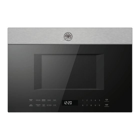
OPERATING INSTRUCTION FEATURES OF YOUR MICROWAVE Front view Bottom view EN-13... -
Page 14: Light O / Noff
CONTROLS SENSOR COOK RESET AUTO VENT SPEED DEFROST +30 SEC 1) Sensor Cook 2) Popcorn 3) Sensor Reheat 4) Power 5) Timer 6) Auto Defrost 7) Turntable ON/OFF 8) Light O / 9) Vent Speed 10) Clock 11) Number Pads 12) Stop/Reset 13) Start/ 30Sec. -
Page 15: Kitchen Timer
Operation 1. Power 11 power levels are available. Level Power 100% Display PL-HI PL-90 PL-80 PL-70 PL-60 PL-50 PL-40 PL-30 PL-20 PL-10 PL-0 2. Power On When the microwave oven is electrified, the screen will display “12:00 “PRESS CLOCK ENTERTIME”. The buzzer will ring once. Press STOP/RESET number keys to set clock or press “... -
Page 16: Lock-Out Function For Children
5 . Time Cook 1)In waiting state,press the number keys to set the cooking time.(The maximum value is 99:99). Power 2) Press " " repeatedly to adjust the power level. The default power is PL -HI. Start/+ 30 Sec 3) Press " "... -
Page 17: Auto Defrost
8. Popcorn Popcorn 1) Press “ ” repeatedly until the number you wish appears in the display. “1”SET: approximate 3.2 ounces “2”SET: approximate 1.75 ounces Popcorn For example, press “ ” once, “3.2” appears in the screen. 2) Press “START/+30SEC” to cook. 9. -
Page 18: Sensor Cook
11. Sensor Cook Sensor Cook 1) Press “ ” once, the screen will display “POTATO”. Sensor Cook Press “ ” repeatedly until the menu you wish appears in the display. TART/+30SEC 3) Press “S ” to start sensor cook mode. The appliance starts sensing. The microwave is operating during sensing. When sensing is complete, beeps will sound and the calculated cook time will start to count down. -
Page 19: Turning The Light On/Off
14. Turning the Light on/off The appliance is equipped with a cooking surface light, to light the surface underneath the appliance. With the “Light On/Off” button you can set two brightness levels. Display Brightness High 15. Turning the turntable on / off For best cooking results, leave the turntable on. -
Page 20: Maintenance
MAINTENANCE Troubleshooting Check your problem by using the chart below and try the solutions for each problem. If the microwave oven still does not work properly, contact the nearest authorized service center. TROUBLE POSSIBLE CAUSE POSSIBLE REMEDY a. Electrical cord for oven is not a. -
Page 21: Installation Instructions
Installation Over the Range Instructions Microwave Oven BEFORE YOU BEGIN Read these instructions completely and carefully. Note to Consumer — Keep these instructions for future IMPORTANT — reference. • Save these instructions Skill level - Installation of this appliance requires basic mechanical for local inspector’s use. -
Page 22: Table Of Contents
Installation Instruction CONTENTS Adapting Microwave Blower for Outside Back Exhaust ........ 37-38 General information Mount the Microwave Oven ......... 39 Important Safety Instructions ..........23 C Recirculating ............40-42 Electrical Requirements ............23 Attach Mounting Plate to Wall ......32 Damage - Shipment/Installation........... -
Page 23: Important Safety Instructions
Installation Instruction IMPORTANT SAFETY INSTRUCTIONS This product requires a three-prong grounded outlet. The You should have the wall receptacle and circuit checked by installer must perform a ground continuity check on the power a qualified electrician to make sure the receptacle is outlet box before beginning the installation to ensure that the properly grounded. -
Page 24: Damage-Shipment/ Installation
Installation Instruction DAMAGE—SHIPMENT/ PARTS INCLUDED (CONT.) INSTALLATION ADDITIONAL PARTS • If the unit is damaged in shipment, return the unit to the PART QUANTITY store in which it was bought for repair or replacement. • Top Cabinet If the unit is damaged by the customer, repair or Template replacement is the responsibility of the customer. -
Page 25: Tools You Will Need
Installation Instruction TOOLS YOU WILL NEED Ruler or tape measure Carpenter square and straight edge (optional) Pencil # 1 Phillips screwdriver Scissors Electric drill with 3/16” and 5/8” Tin snips (for cutting damper, if (to cut template, if necessary) drill bits required) Filler blocks or scrap wood pieces, if needed for top cabinet... -
Page 26: Placement Of The Mounting Plate
Installation Instruction 1 PLACEMENT OF THE MOUNTING PLATE A. REMOVING THE MICROWAVE Cut the middle of the outer protective plastic bag to OVEN FROM THE CARTON/ remove the ounting late. REMOVING THE MOUNTING Screws Screws PLATE Mounting Plate Remove the installation instructions, use and care, exhaust adapter, turntable ring, shelf, filters, glass tray and the small hardware bag. -
Page 27: Determining Wall Plate Location
Installation Instruction C. DETERMINING WALL PLATE LOCATION UNDER YOUR CABINET Plate position-beneath flat bottom Plate position-beneath framed cabinet recessed cabinet bottom NOTE: READ IT IS VERY IMPOR IN THE AND FOLLO TANT BEFOR INSTA LLATIO W THE DIREC REAR E PROC N INSTR TIONS WALL... -
Page 28: Aligning The Wall Plate
Installation Instruction D. ALIGNING THE WALL PLATE 3/8" TO EDGE 12" Trim the rear wall template along the dotted line. NOTE: IT IS VERY IMPORTANT TO READ AND FOLLOW THE DIRECTIONS IN THE INSTALLATION INSTRUCTIONS BEFORE PROCEEDING WITH THIS REAR WALL TEMPLATE. This Rear Wall Template serves to position the bottom 4"... -
Page 29: Installation Types
Installation Instruction 2 INSTALLATION TYPES (Choose A, B or C) NOTE: This microwave is shipped assembled for This microwave oven is designed for adaptation to the following three types of ventilation: Recirculating. Select the type of ventilation required for A. Outside Top Exhaust (Vertical Duct) your installation and proceed to that section. -
Page 30: Outside Top Exhaust (Example Only)
Installation Instruction INSTALLATION INSTRUCTIONS FOR EXTERNAL EXHAUST DUCTING NOTE: If you need to install ducts, note that the total duct length of Maximum duct length: 31/4" x 10” (8.2 x 25.4 cm) rectangular or 5” (12.7 cm) diameter/ 6” For satisfactory air movement, the total duct length of x 10 ”... -
Page 31: Outside Back Exhaust (Example Only)
Installation Instruction EQUIVALENT NUMBER EQUIVALENT DUCT PIECES LENGTH USED LENGTH Roof Cap 24 Ft. (7.3 m) 24 Ft. (7.3 m) 12 Ft. (3.6 m) 12 Ft. (3.6 m) 12 Ft. (3.6 m) Straight Duct (6”/15.2 cm Round) Rectangular-to-Round 5 Ft. (1.5 m) 5 Ft. -
Page 32: Preparation Of Top Cabinet
Installation Instruction A OUTSIDE TOP EXHAUST (Vertical Duct) INSTALLATION OVERVIEW A1. Attach Mounting Plate to Wall A2. Prepare Top Cabinet A3. Adapting Microwave Blower for Outside Top Exhaust 3/8" TO EDGE A4. Check Damper Operation along the dotted line. Trim the rear wall template 12"... -
Page 33: Preparation Of Top Cabinet
Installation Instruction A2. USE TOP CABINET TEMPLATE FOR Carefully pull out the blower unit. The wires will extend far enough to allow you to adjust the blower unit. PREPARATION OF TOP CABINET End B You need to drill holes for the top support screws, a hole large enough for the power cord to fit through, and a cutout large enough for the exhaust adaptor. -
Page 34: Outside Top Exhaust
Installation Instruction A3. ADAPTING MICROWAVE BLOWER FOR A5. MOUNT THE MICROWAVE OVEN OUTSIDE TOP EXHAUST 5 Secure blower unit to microwave with the screw removed in Step 1. Make sure the screw is tight. 6 Replace blower plate with the screw removed in Step 1. Make sure the screw is tight. -
Page 35: Adjust The Exhaust Adaptor
Installation Instruction A5. MOUNT THE MICROWAVE OVEN A6. ADJUST THE EXHAUST ADAPTOR (cont.) Open the top cabinet and adjust the exhaust adaptor to connect to Cabinet Front the house duct. Back of Cabinet Bottom Shelf Damper Blower Plate Microwave Filler Block Equivalent to Depth of Cabinet... -
Page 36: B Outside Back Exhaust
Installation Instruction B OUTSIDE BACK EXHAUST (Horizontal Duct) INSTALLATION OVERVIEW B1. Prepare Rear Wall B2. Remove Blower Plate B3. Attach Mounting Plate to Wall B4. Prepare Top Cabinet B5. Adjust Blower 3/8" TO EDGE along the dotted line. Trim the rear wall template 12"... -
Page 37: Attach Mounting Plate To Wall
Installation Instruction B3. ATTACH THE MOUNTING PLATE TO THE WALL • Read the instructions on the TOP CABINET TEMPLATE. • Tape it underneath the top cabinet. • Drill the holes, following the instructions on the TOP CABINET TEMPLATE. Attach the plate to the wall using toggle bolts. CAUTION: Wear safety goggles when drilling holes in the cabinet At least one wood screw must be used to attach the plate to a wall bottom. - Page 38 Installation Instruction After Rotation AFTER: Fan Blade Before Rotation Openings Facing Back End A End B Back of Back of Microwave Microwave CAUTION: Do not pull or stretch the blower unit 5 Gently remove the wires from the grooves. wiring. Make sure the wires are not pinched, and that they are properly secured.
-
Page 39: B5. Mount The Microwave Oven
Installation Instruction B5. MOUNT THE MICROWAVE OVEN Cabinet Front Cabinet Bottom Shelf Filler Block Equivalent to Depth of Cabinet Recess FOR EASIER INSTALLATION AND PERSONAL SAFETY, WE RECOMMEND THAT TWO PEOPLE INSTALL THIS Self-Aligning Screw MICROWAVE OVEN. IMPORTANT: Do not grip or use the handle or heat shield Microwave Oven Top during installation. -
Page 40: C1. Attach The Mounting Plate To The Wall
Installation Instruction INSTALLATION OVERVIEW C1. Attach Mounting Plate to Wall C2. Prepare Top Cabinet C3. Check Blower Plate 3/8" TO EDGE along the dotted line. Trim the rear wall template 12" C4. Mount the Microwave Oven NOTE: IT IS VERY IMPORTANT READ AND FOLLOW THE DIRECTIONS IN THE INSTALLATION... -
Page 41: C Recirculating
Installation Instruction C RECIRCULATING (Non-Vented Ductless) C4. MOUNT THE MICROWAVE OVEN C2. USE TOP CABINET TEMPLATE FOR PREPARATION OF TOP CABINET You need to drill holes for the top support screws and a hole large enough for the power cord to fit through. FOR EASIER INSTALLATION AND PERSONAL SAFETY, WE RECOMMEND THAT TWO PEOPLE INSTALL THIS MICROWAVE OVEN. -
Page 42: Installing Or Change The Charcoal Filter
Installation Instruction 2 Open the microwave door and remove the two vent mounting C4. MOUNT THE MICROWAVE OVEN screws located on top of the microwave using a #1 Phillips (cont.) screwdriver. Charcoal Filte Insert 2 self-aligning screws through outer top cabinet holes. Turn two full turns on each screw. - Page 43 Installation Instruction 5 Press the bottom of charcoal filter to place it into the correct position. 6 Reinstall the vent by sliding the bottom of the vent into place. Push the vent top into position and slide right into place. Replace the two vent mounting screws located on top of the microwave using a #1 Phillips screwdriver.
-
Page 44: Before You Use Your Microwave
Installation Instruction BEFORE YOU USE YOUR MICROWAVE Make sure the microwave oven has been installed according Replace house fuse or turn breaker back on. to instructions. Remove all packing material from the microwave oven. Read the USE & CARE Manual. Install turntable ring and glas s tray in cavity. -
Page 45: Customer Care
CUSTOMER CARE For any warranty information and service request, contact us: In USA: https://us.bertazzoni.com/more/support In Canada: https://ca.bertazzoni.com/more/support... - Page 49 Ce manuel vous aidera à apprendre à utiliser et à entretenir votre appareil Bertazzoni de la manière la plus sûre et la plus efficace, afin qu’il puisse vous donner la plus grande satisfaction pour les années à venir.
-
Page 51: Four À Micro-Ondes
Four à micro-ondes MODE D’EMPLOI Modèle : KOTR24XV Lisez attentivement ce mode d’emploi avant d’utiliser votre four à micro-ondes et conservez-le soigneusement. Si vous suivez les instructions qu’il contient, votre four vous fournira de nombreuses années de bon service. CONSERVER SOIGNEUSEMENT CE MODE D’EMPLOI... -
Page 52: Spécifications
PORTE (pliée) CHARNIÈRES ET LOQUETS (cassés ou desserrés) JOINTS DE PORTE ET SURFACES D’ÉTANCHÉITÉ (d) Le four doit être réglé ou réparé uniquement par un technicien d’entretien dûment qualifié. Spécifications KOTR24XV Modèle 120 VAC,60 Hz Tension nominale 1500 W Entrée micro-ondes... -
Page 53: Instructions De Sécurité Importantes
INSTRUCTIONS DE SÉCURITÉ IMPORTANTES Lors de l’utilisation d’appareils électriques, il convient d’observer les précautions de sécurité de base, à savoir : AVERTISSEMENT - Pour réduire le risque de brûlures, de chocs électriques, d’incendie, de blessures corporelles ou d’exposition excessive à l’énergie des micro-ondes : Lire toutes les instructions avant d’utiliser l’appareil. - Page 54 CONSERVER SOIGNEUSEMENT CES INSTRUCTIONS ! INSTRUCTIONS POUR LA MISE À LA TERRE Cet appareil doit être relié à la terre. En cas de court-circuit électrique, la mise à la terre réduit le risque de choc électrique en fournissant une déviation du courant électrique vers le sol. Cet appareil est équipé d’un cordon doté d’un fil de mise à la terre et d’une fiche de mise à...
-
Page 55: Interférences Radio
INTERFÉRENCES RADIO Ce produit a été testé et jugé conforme aux limites du four à micro-ondes, conformément à la section 18 de la réglementation FCC. Ce produit peut émettre de l’énergie radio-fréquence, ce qui pourrait causer des interférences à des produits tels que radio, télévision, moniteur pour bébé, téléphone sans fil, Bluetooth, routeur sans fil, etc., ce qui peut être confirmé... - Page 56 Matériaux adaptés pour la cuisson au micro-ondes Ustensiles Remarques Plat brunisseur Suivre les instructions du fabricant*. La base du plat brunisseur doit être d’au moins 3/16 po (5 mm) au-dessus de la plaque tournante. Une utilisation incorrecte peut provoquer la rupture du plateau tournant. Vaisselle N’utiliser que des ustensiles allant au micro-ondes.
- Page 57 Matériaux adaptés pour la cuisson au micro-ondes Ustensiles Remarques Plateau en Peut être source d’étincelles. Utiliser un plat pouvant aller au micro- aluminium ondes à la place, Boîte en carton Peut être source d’étincelles. Utiliser un plat pouvant aller au micro- pour produits ondes à...
-
Page 58: Instructions D'utilisation
INSTRUCTIONS D’UTILISATION CARACTÉRISTIQUES DU FOUR À MICRO-ONDES Vue avant Vue du dessous Porte Plateau rotatif en verre Fenêtre d’observation Grille supérieure Système de verrouillage de sécurité Cordon d’alimentation Panneau de commande Lampes de surface Anneau pour plateau rotatif Filtres à graisses Axe pour plateau rotatif FR-58... - Page 59 COMMANDES SENSOR COOK RESET AUTO VENT SPEED DEFROST +30 SEC Cuisson par capteur Popcorn Réchauffage par capteur Puissance Minuteur Décongélation automatique Plateau tournant Marche/Arrêt Éclairage Marche/Arrêt Vitesse de ventilation 10) Horloge 11) Pavé numérique 12) Arrêter/Réinitialiser 13) Start/+ 30Sec. 14) Écran d’affichage FR-59...
-
Page 60: Niveau De Puissance
Fonctionnement 1. Niveau de puissance 11 niveaux de puissance sont disponibles. Niveau Puissance 100 % 90 % 80 % 70 % 60 % 50 % 40 % 30 % 20 % 10 % Afficheur PL-HI PL-90 PL-80 PL-70 PL-60 PL-50 PL-40 PL-30 PL-20 PL-10 PL-0 2. -
Page 61: Temps De Cuisson
5. Temps de cuisson 1) En mode d’attente, appuyer sur les touches numériques pour régler le temps de cuisson. (La valeur maximale est de 99:99). Power » 2) Appuyer plusieurs fois sur « pour régler le niveau de puissance. Le niveau de puissance par défaut est PL-HI. Start/+30Sec »... -
Page 62: Décongélation Automatique
8. Popcorn Popcorn 1) Appuyer plusieurs fois sur la touche « » jusqu’à ce que la quantité souhaitée s’affiche. « 1 » SET: correspond approximativement à 3,2 onces « 2 » SET: correspond approximativement à 1,75 onces Popcorn Par exemple, appuyer une fois sur la touche « », «... -
Page 63: Réchauffage Par Capteur
10. Réchauffage par capteur Sensor Reheat 1) Appuyer une fois sur la touche « », l’écran affichera « BEVERAGE » . Sensor Reheat Appuyer plusieurs fois sur la touche « » jusqu’à ce que le menu souhaité s’affiche. 3) Appuyer sur « START/+30SEC »... -
Page 64: Cuisson Par Capteur
11. Cuisson par capteur Sensor 1) Appuyer une fois sur la touche « Cook», l’écran affichera « POTATO ». Sensor Appuyer plusieurs fois sur « Cook » jusqu’à ce que le menu souhaité s’affiche. TART/+30SEC 3) Appuyer sur « S »... -
Page 65: Activation/Désactivation Du Plateau Tournant
14. Activation/Extinction de l’éclairage L’appareil est équipé d’une lumière de surface de cuisson, pour éclairer la surface sous l’appareil. Il est possible de définir deux niveaux de luminosité à l’aide de la touche « Light On/Off ». Afficheur Luminosité Forte Faible Extinction 15. -
Page 66: Entretien
ENTRETIEN Résolution des problèmes Vérifier le problème en utilisant le tableau ci-dessous et essayer les solutions pour chaque problème. Si le four à micro-ondes ne fonctionne toujours pas correctement, contacter le centre de service agréé le plus proche. PROBLÈME CAUSE POSSIBLE SOLUTION POSSIBLE La fiche du four n’est pas Brancher la fiche dans la prise... -
Page 67: Instructions D'installation
Instructions Four à micro-ondes à d’installation hotte intégrée AVANT DE PROCÉDER À L’INSTALLATION Lire attentivement toutes les informations fournies ci-après. Remarques à l’intention du consommateur — IMPORTANT — Conserver le présent manuel pour toute consultation future. • Conserver ce manuel pour Niveau de compétence - L’installation de cet appareil nécessite des tout contrôle éventuel de l’inspecteur local. - Page 68 Instructions d’installation SOMMAIRE Réglage du ventilateur du micro-ondes pour l’échappement arrière vers l’extérieur ..83-84 Informations générales Montage du four micro-ondes ....... 85 Consignes de sécurité importantes ........6 C Recirculation de l’air ..........86-88 Exigences électriques ............6 Fixer la plaque de montage à la paroi ....86 Dommages - Expédition/Installation ........
-
Page 69: Exigences Électriques
Instructions d’installation INSTRUCTIONS DE SÉCURITÉ IMPORTANTES Ce produit nécessite une sortie de terre à trois broches. Faire vérifier la prise murale et le circuit par un électricien L’installateur doit effectuer une vérification de la continuité de qualifié pour s’assurer que la prise est correctement mise à la mise à... -
Page 70: Dommages - Expédition/Installation
Instructions d’installation DOMMAGES— PIÈCES INCLUSES (SUITE) EXPÉDITION/ PIÈCES SUPPLÉMENTAIRES INSTALLATION PIÈCE QUANTITÉ • Si l’appareil est endommagé pendant l’expédition, le Gabarit meuble haut retourner au magasin dans lequel il a été acheté pour réparation ou remplacement. Gabarit paroi • Si l’appareil est endommagé par le client, la réparation ou arrière le remplacement est à... -
Page 71: Outillage Requis
Instructions d’installation OUTILLAGE REQUIS Mètre ruban et règle Équerre de charpentier Crayon (en option) # 1 Tournevis cruciforme Cisailles (pour la découpe de Ciseaux l’amortisseur, si nécessaire) (Pour la découpe du gabarit, si Perceuse électrique avec nécessaire) mèches de 3/16’’ et de 5/8’’ Blocs de remplissage ou chutes de bois, si nécessaire pour l’espacement du meuble haut... -
Page 72: Installation De La Plaque De Montage
Instructions d’installation 1 INSTALLATION DE LA PLAQUE DE MONTAGE A. RETRAIT DU FOUR À MICRO- Couper le milieu du sac en plastique de protection extérieur pour retirer la plaque de montage. ONDES DU CARTON/RETRAIT DE LA PLAQUE DE MONTAGE Plaque de montage Retirer les instructions d’installation, le manuel d’utilisation et d’entretien, l’adaptateur d’échappement, l’anneau de roulement, la grille, les filtres, le plateau en... -
Page 73: Identification De L'emplacement De La Plaque Murale
Instructions d’installation C. IDENTIFICATION DE L’EMPLACEMENT DE LA PLAQUE MURALE SOUS L’ARMOIRE Position de la plaque-sous l’armoire à Position de la plaque- sous le fond en fond plat retrait du cadre de l’armoire NOTE: READ IT IS VERY IN THE AND FOLLO IMPOR TANT... -
Page 74: Alignement De La Plaque Murale
Instructions d’installation D. ALIGNEMENT DE LA PLAQUE MURALE 3/8" TO EDGE 12" Trim the rear wall template along the dotted line. NOTE: IT IS VERY IMPORTANT TO READ AND FOLLOW THE DIRECTIONS IN THE INSTALLATION INSTRUCTIONS BEFORE PROCEEDING WITH THIS REAR WALL TEMPLATE. -
Page 75: Types D'installation
Instructions d’installation 2 TYPES D’INSTALLATION (Choisir A, B ou C) REMARQUE : Ce four à micro-ondes est expédié Ce four à micro-ondes est conçu pour s’adapter aux trois types de ventilation suivants : assemblé pour la recirculation de l’air. Sélectionner le A. -
Page 76: Hotte À Évacuation
Instructions d’installation INSTRUCTIONS D’INSTALLATION DU CONDUIT D’ÉVACUATION VERS L’EXTÉRIEUR REMARQUE : En cas d’installation d’un conduit, noter que la Longueur maximale du conduit : longueur totale du conduit rectangulaire de 31/4’’ x 10’’ (8,2 x Pour un mouvement d’air satisfaisant, la longueur totale du 25,4 cm), ou du conduit circulaire de 5’’... - Page 77 Instructions d’installation CONDUIT D’ÉVACUATION VERS L’EXTÉRIEUR ÉCHAPPEMENT HAUT VERS L’EXTÉRIEUR (EXEMPLE UNIQUEMENT) Le tableau suivant fournit un exemple d’installation possible de conduits. LONGUEUR NOMBRE LONGUEUR PIÈCES DE CONDUIT ÉQUIVALENTE UTILISÉ ÉQUIVALENTE Chapeau de toit 24 pi (7,3 m) 24 pi (7,3 m) 12 pi (3,6 m) 12 pi (3,6 m) 12 pi (3,6 m)
-
Page 78: A Échappement Haut Vers L'extérieur
Instructions d’installation A ÉCHAPPEMENT HAUT VERS L’EXTÉRIEUR (Conduit vertical) VUE D’ENSEMBLE DE L’INSTALLATION A1. Fixer la plaque de montage à la paroi A2. Préparer le meuble haut A3. Réglage du ventilateur du micro- ondes pour l’échappement haut vers l’extérieur 3/8" TO EDGE A4. -
Page 79: Réglage Du Ventilateur Du Micro-Ondes Pour L'échappement Haut Vers L'extérieur
Instructions d’installation A2. PRÉPARATION DU MEUBLE HAUT A Retirer délicatement le ventilateur. Les fils s’étendront suffisamment loin pour permettre d’ajuster facilement le L’AIDE DU GABARIT RESPECTIF ventilateur. Il est nécessaire de percer des trous pour les vis du support Extrémité B supérieur, un trou suffisamment grand pour le passage du cordon d’alimentation, et une découpe assez grande pour l’adaptateur d’échappement. -
Page 80: Contrôle Du Bon Fonctionnement De L'amortisseur
Instructions d’installation A3. RÉGLAGE DU VENTILATEUR DU A5. MONTAGE DU FOUR À MICRO- MICRO-ONDES POUR L’ÉCHAPPEMENT ONDES HAUT VERS L’EXTÉRIEUR 5 Fixer le ventilateur au micro-ondes à l’aide de la vis déposée à l’Étape 1. Vérifier que la vis est bien serrée. Réinstaller la plaque du ventilateur à... -
Page 81: Réglage De L'adaptateur D'échappement
Instructions d’installation A5. MONTAGE DU FOUR À MICRO- A6. RÉGLAGE DE L’ADAPTATEUR ONDES (suite) D’ÉCHAPPEMENT Avant de Ouvrir le meuble haut et ajuster l’adaptateur d’échappement pour le l’armoire Étagère inférieure de raccorder au conduit de l’habitation. l’armoire Dos du four à Bloc de Amortisseur Plaque du ventilateur... -
Page 82: B Échappement Arrière Vers L'extérieur
Instructions d’installation B ÉCHAPPEMENT ARRIÈRE VERS L’EXTÉRIEUR (Conduit horizontal) VUE D’ENSEMBLE DE L’INSTALLATION B1. Préparer la paroi arrière B2. Déposer la plaque du ventilateur B3. Fixer la plaque de montage à la paroi 3/8" TO EDGE along the dotted line. Trim the rear wall template 12"... -
Page 83: Fixer La Plaque De Montage À La Paroi
Instructions d’installation B3. FIXER LA PLAQUE DE MONTAGE À LA PAROI • Lire les instructions relatives au GABARIT MEUBLE HAUT. • Le coller sous le meuble haut. • Percer les trous en suivant les instructions du GABARIT MEUBLE HAUT. Fixer la plaque à la paroi à l’aide de boulons à ailettes. MISE EN GARDE : Se munir de lunettes de sécurité... - Page 84 Instructions d’installation L’EXTÉRIEUR (suite) APRÈS : Ouvertures des aubes du ventilateur 4 Faire pivoter le ventilateur de 180° en le tournant dans le sens orientées vers l’arrière inverse des aiguilles d’une montre. Extrémité A Après rotation Avant rotation Extrémité B MISE EN GARDE : Ne pas tirer ou tendre le câblage du ventilateur.
-
Page 85: Montage Du Four Micro-Ondes
Instructions d’installation B6. MONTAGE DU FOUR À MICRO- Avant de l’armoire ONDES Étagère inférieure de l’armoire Bloc de remplissage Égal à la profondeur du renfoncement de l’armoire POUR FACILITER L’INSTALLATION ET LA SÉCURITÉ Vis auto-alignante PERSONNELLE, NOUS RECOMMANDONS QUE DEUX PERSONNES SOIENT PRÉSENTES POUR INSTALLER CE Dessus du four à... -
Page 86: C Recirculation De L'air
Instructions d’installation C RECIRCULATION (Non ventilé Sans conduit) VUE D’ENSEMBLE DE L’INSTALLATION C1. Fixer la plaque de montage à la paroi C2. Préparer le meuble haut 3/8" TO EDGE along the dotted line. Trim the rear wall template C3. Contrôler la plaque du ventilateur 12"... -
Page 87: Préparation Du Meuble Haut
Instructions d’installation C4. MONTAGE DU FOUR À MICRO-ONDES C2. PRÉPARATION DU MEUBLE HAUT A L’AIDE DU GABARIT RESPECTIF Il est nécessaire de percer des trous pour les vis du support supérieur et un trou suffisamment grand pour faire passer le cordon d’alimentation. -
Page 88: Installer Ou Remplacer Le Filtre À Charbon
Instructions d’installation 2 Ouvrir la porte du four à micro-ondes et déposer les deux vis C4. MONTAGE DU FOUR À MICRO- de montage du ventilateur situées sur le dessus du four à micro- ONDES (suite) ondes à l’aide d’un tournevis cruciforme #1. Filtre à... - Page 89 Instructions d’installation 5 Appuyer sur le bas du filtre à charbon pour l’installer dans la position correcte. 6 Saisir le ventilateur par le bas et le remettre en place en le faisant glisser. Pousser le haut du ventilateur, puis le faire glisser dans sa position définitive.
-
Page 90: Avant D'utiliser Le Four Micro-Ondes Pour La Première Fois
Instructions d’installation AVANT D’UTILISER LE FOUR A MICRO-ONDES S’assurer que le four à micro-ondes a été installé Réinstaller le fusible de l’habitation ou réactiver le conformément aux instructions. disjoncteur. Lire le manuel UTILISATION ET ENTRETIEN. Retirer tout le matériel d’emballage du four à micro-ondes Installer l’anneau de roulement et le plateau en verre dans la cavité. -
Page 91: Service Clientèle
SERVICE CLIENTÈLE Pour toute information sur la garantie et demande de service, contactez-nous: Aux États-Unis : https://us.bertazzoni.com/more/support Au Canada: https://ca.bertazzoni.com/more/support... - Page 94 Via Palazzina, 8, 42016 Guastalla RE © 2023 BERTAZZONI. All rights reserved. KOTR24XV_v.01 PN:16170000B05516...
Need help?
Do you have a question about the KOTR24XV and is the answer not in the manual?
Questions and answers