
Related Manuals for PICARRO PI5310


Summary of Contents for PICARRO PI5310
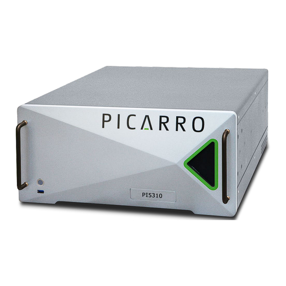
- Page 1 PI5310 Analyzer for N O, CO, H O User Manual Picarro Inc. 3105 Patrick Henry Drive Santa Clara, CA 95054, USA Phone: +1 408 962 3900 www.picarro.com Document Number 40-0103 Revision A...
-
Page 2: Picarro Notices
DISCLAIMER AND RESERVATION OF RIGHTS Picarro has prepared this manual solely for the information and use by its customers as a guide for the selection, installation, operation, and maintenance of the products described. -
Page 3: Table Of Contents
Rack Mount Instructions ................31 Electrical Connections ................34 Chiller Laser Cooling .................. 35 Analyzer Basic Operation .................. 40 Startup ......................40 Shutdown ....................42 Analyzer Restart after Electrical Power Outage .......... 44 Picarro Launch Pad ..................44 PI5310 UM P/N 40-0103 Rev. A... - Page 4 Discrete Input Register Map ............... 79 Holding Register Map ................. 80 Coil Register Map ..................81 10. Serial Communication ..................84 10.1 COM1 (Command Interface) Protocol ............85 10.2 COM2 (Data Manager) Data Streaming Protocol ........86 P/N 40-0103 Rev. A PI5310 UM...
- Page 5 APPENDIX G – External Valve Sequencer.............. 127 G.1 Introduction ....................127 G.2 A0311 16-Port Distribution Manifold ............127 G.3 A0311-S 16-Port Distribution Manifold (Silco) ..........128 G.4 Valve Control Configurations ............... 129 G.5 Setting Up Solenoid Valves ................. 129 PI5310 UM P/N 40-0103 Rev. A...
- Page 6 I.3 Converting Absorption Intensity to Concentration .......... 140 I.4 Spectral Precision and High Sensitivity Measurements ......... 141 APPENDIX J – SDS for Koolance LIQ-702 .............. 143 APPENDIX K – Limited Warranty ................159 About Picarro ......................161 Product Support....................... 161 P/N 40-0103 Rev. A PI5310 UM...
-
Page 7: List Of Figures
List of Figures Figure 1: PI5310 Front/Back Panels ................12 Figure 2: PI5310 LED Status Indicator ................. 13 Figure 3: A2000 Vacuum Pump – Side Views .............. 13 Figure 4: Laser Safety Label – Affixed to Outside Cover of Analyzer ......20 Figure 5: Laser Safety Label –... - Page 8 Figure 31: Clock Set Dialog ..................49 Figure 32: Clock Set Menu ................... 50 Figure 33: Clock Set Dialog ..................50 Figure 34: Layout of PI5310 Analyzer GUI ..............52 Figure 35: CRDS Toolbar Options ................53 Figure 36: Alarm Panel ....................54 Figure 37: Alarm Set Dialog ..................
- Page 9 Figure 77: Concatenated Output .h5 Filename............108 Figure 78: Time Series Selection Options ..............108 Figure 79: Picarro Data File Viewer – File Menu ............109 Figure 80: Picarro Data File Viewer – New Menu ............110 Figure 81: Select Variables Form ................111 Figure 82: Define Date Range Dialog ................
- Page 10 Figure 105: External Valve Sequencer UI ..............132 Figure 106: Example 15 Minute Sequence ..............134 Figure 107: Schematic of Picarro CRDS Analyzer Cavity........... 139 Figure 108: Light Intensity as Function of Time in CRDS System ......140 Figure 109: Absorption Spectral Curve ..............141 P/N 40-0103 Rev.
-
Page 11: List Of Tables
Table 12: Coil Register Map ..................81 Table 13: Alarm Status Bit Assignment ................ 96 Table 14: Alarm Status Definitions ................96 Table 15: PI5310 Data Log Columns ................97 Table 16: Analog Signal Output Settings ..............104 PI5310 UM... -
Page 12: Introduction
The PI5310 analyzer measures concentrations of N O, CO and H O using Picarro’s patented Cavity Ring-Down Spectroscopy (CRDS). The analyzer can be deployed for air monitoring applications in a lab or in the field, allowing in-situ analysis of trace and ambient amounts of N... -
Page 13: Analyzer Specifications
System Alarm Panel on the CRDS Data Viewer Screen. See Section 5 Analyzer Basic Operation. Figure 2: PI5310 LED Status Indicator A2000 Vacuum Pump The A2000 vacuum pump (Figure 3) is used to maintain cavity pressure inside the analyzer. - Page 14 100 – 240 VAC; 50 – 60 Hz (auto-sensing) 250 W Mains Supply Voltage Fluctuation 150 W (pump) ±10% of the nominal voltage Minimum Rated Circuit 10A @ 115 VAC Amperage 5A @ 230 VAC Liquid Ingress Protection None P/N 40-0103 Rev. A PI5310 UM...
-
Page 15: Acronyms
Electrostatic Discharge Length in feet;1 ft. = 12” or 12 inches (30.48 cm) Graphical User Interface Water, Water Vapor Hierarchical Data Format Hertz Inside Diameter (i.e., .5” ID) or Identification (i.e., Slave ID) Kilograms PI5310 UM P/N 40-0103 Rev. A... - Page 16 PSIG Pounds per Square Gauge Water vapor pressure Relative Humidity RJ-45 Registered Jack (physical network interface) RS232 Recommended Standard 232 (serial communication protocol) SCCM Standard cubic centimeters per minute SS / SST Stainless Steel P/N 40-0103 Rev. A PI5310 UM...
-
Page 17: Text Conventions
Bold Italic text identifies section reference links. • Bold text is for actions to take (such as clicking on a UI button), caution • and warning statements, and text you should type or select in screens. PI5310 UM P/N 40-0103 Rev. A... -
Page 18: Safety
WARNING HOT SURFACE alerts user to potential injury from hot surfaces. CAUTION REMINDER is a helpful hint for procedures listed in the text. REMINDER P/N 40-0103 Rev. A PI5310 UM... -
Page 19: General Safety
• requirements for electrical equipment for measurement, control, and laboratory use. Using this analyzer in a manner not specified by Picarro may result in damage to the analyzer and render it unsafe to operate. WARNING The analyzer is for indoor use only and has an ingress protection rating of IPx-0. -
Page 20: Laser Safety
WARNING The following Laser Safety Label is affixed to the outer cover of the analyzer. Figure 4: Laser Safety Label – Affixed to Outside Cover of Analyzer P/N 40-0103 Rev. A PI5310 UM... -
Page 21: Figure 5: Laser Safety Label - Affixed To Inside Of Analyzer
The following Laser Safety Label (Figure 5) is affixed to the inside of the analyzer: Figure 5: Laser Safety Label – Affixed to Inside of Analyzer Use of controls or adjustments or performance of procedures other than those specified herein may result in hazardous radiation exposure. CAUTION PI5310 UM P/N 40-0103 Rev. A... -
Page 22: Unpacking
Unpacking 3. Unpacking Inspect the Shipping Container Picarro products are inspected and tested before leaving the factory. Their packing containers have been designed to keep the equipment safe from damage during transit. Picarro SI5000 series shipping containers consist of: A wooden crate with metal clamps •... -
Page 23: Unpack Components
Keep the shipping materials to reuse when transporting the analyzer. • Contact Picarro for options on transporting systems to remote labs. The analyzer weighs 32.2 kg (71 lbs). Use the technique outlined on Page 20 when lifting or moving the analyzer. -
Page 24: Table 4: Pi5350: Shipping Container Contents
Nut (1) and Ferrules (2) For connecting input line to analyzer gas input. Coolant 1 bottle of Koolance 702 liquid coolant. Document Packet (1) Includes this user manual and certificate of compliance (not shown). P/N 40-0103 Rev. A PI5310 UM... -
Page 25: Hardware Setup
WARNING damage to the optics. Picarro sells certain USB enabled devices, such as GPS, which are approved for use. Do not connect USB hubs or unauthorized USB devices (except flash drives, mice, and keyboards) to the USB ports. Unauthorized USB devices may WARNING interfere with the normal functioning of the analyzer. - Page 26 WARNING Use the AC power cables supplied with the analyzer or a similarly rated cable. Check with Picarro technical support if you have questions about power cable replacement. An inadequately rated power cable can result in equipment CAUTION damage.
-
Page 27: Analyzer Preparation
Remove the analyzer and the external vacuum pump from the shipping container. Install the analyzer in a rack or place it on a cart or table. Place the external vacuum pump near the analyzer in a rack, or on a cart or table. PI5310 UM P/N 40-0103 Rev. A... -
Page 28: Connections - A2000 Pump And Gas Inlet
Unpack the analyzer accessories (vacuum line, cable kit, manual, and certificate of compliance). Store the certificate of compliance in a safe place. It may be required if you contact Picarro for service or questions. NOTE Remove the caps from the analyzer Sample inlet and Vacuum connection ports. -
Page 29: Figure 9: Analyzer Setup With A2000 Pump
Connect the provided vacuum line between the analyzer port labeled VACUUM and the pump vacuum inlet. If working with hazardous gases, see APPENDIX F – for instructions on directing the pump exhaust to a safe venting environment. PI5310 UM P/N 40-0103 Rev. A... -
Page 30: Figure 10: Orientation Of Inlet Nut And Ferrules (Sst Tubing)
When making a new PFA gas inlet connection: Use 1/4” OD PFA tubing and connector sets to connect from sample source to the sample inlet. Place the two PFA ferrules inside the PFA nut as shown in Figure 11. P/N 40-0103 Rev. A PI5310 UM... -
Page 31: Rack Mount Instructions
It must be supported by a shelf, or by user-provided “L” type support brackets. WARNING Remove the rack-mounting rails from shipping crate and remove packaging. Extend each rail. Press the blue PUSH HERE button and remove the narrow inner slide from the assembly. PI5310 UM P/N 40-0103 Rev. A... -
Page 32: Figure 12: Inner Rail Slide Removal
Repeat on the other side of the analyzer. Figure 13: Attaching Inner Slide Rails to Analyzer Attach a front panel restraint (Figure 14) to each side of the analyzer using two included M4 x 8 button-head screws. P/N 40-0103 Rev. A PI5310 UM... -
Page 33: Figure 14: Locking Bracket Installed
This may be necesssary to prevent clearance issues with adjacent instruments within the rack. This analyzer weighs 47 lbs (21.3 kg) When lifting the analyzer, use the technique described in the Safety section of this document (or follow your local regulations) . WARNING PI5310 UM P/N 40-0103 Rev. A... -
Page 34: Electrical Connections
7. Rocker power switch 16. Display Port 8. AC Line power receptacle 17. USB Ports (4 ea.) 9. Ethernet Ports – RJ-45 (2 ea.) 18. Audio In/Out Ports Figure 16: Annotated Rear Panel Diagram P/N 40-0103 Rev. A PI5310 UM... -
Page 35: Chiller Laser Cooling
Inspect the water level in the reservoir every six months; add or refresh • coolant in case of water loss or contamination. A bottle of coolant (manufacturer: Koolance, part number: LIQ-702CL-B) is • shipped with the analyzer. PI5310 UM P/N 40-0103 Rev. A... -
Page 36: Chiller Setup
Chiller Setup Inspect the water buffer tank for possible cracks, and external water tube breakage. If damage is observed, stop, and contact Picarro support to get the damage repaired before adding coolant. WARNING Figure 17: Reservoir Connections at Time of Shipment Rotate the black top lid counter-clockwise to open the tank as shown in Figure 18. -
Page 37: Figure 18: Reservoir Inspection
Hardware Setup Figure 18: Reservoir Inspection Fill the reservoir so that the coolant covers the sponge and reaches the last thread for the top lid. See Figure 19. Figure 19: Proper Coolant Level in Reservoir PI5310 UM P/N 40-0103 Rev. A... -
Page 38: Figure 20: Reservoir Connected And Ready To Run
Make sure bubbles are forming. Figure 21: Confirmation of Coolant Flow Replace the lid and tighten it clockwise. P/N 40-0103 Rev. A PI5310 UM... -
Page 39: Chiller Maintenance
The reference coolant flow rate is typically as 0.25 lpm (liter per minute). A minimal flow rate of 0.15 lpm or above is required for laser cooling. NOTE PI5310 UM P/N 40-0103 Rev. A... -
Page 40: Analyzer Basic Operation
This section explains how to operate the analyzer using the GUI. It describes system startup, shutdown, and recovery procedures, desktop features. GUI Functions are detailed in section Using this analyzer in a manner not specified by Picarro may result in damage to the analyzer and render it unsafe to operate. WARNING... - Page 41 (coordinator) is used to control the sample source and match the corresponding real time read out with the sample source. Depending on system configuration, coordinator programs may not be included. PI5310 UM P/N 40-0103 Rev. A...
-
Page 42: Shutdown
Shutdown This section describes how to safely shutdown the analyzer using dry gas, closing the CRDS application, and powering off the instrument from the Picarro Launch Pad. A flow of clean, dry gas should always be directed to the instrument for several minutes prior to shutting down. -
Page 43: Figure 23: Analyzer Shutdown Dialog
Leave any dry gas or desiccant attached to the inlet during this process. NOTE 11. From the Picarro Launch Pad select Power Off to tun off the hardware. 12. When the instrument fans audibly turn off, and when the green power button light on the front of the instrument turns off, shut off the pump manually from the rocker switch located on the pump. -
Page 44: Analyzer Restart After Electrical Power Outage
Picarro Launch Pad The Picarro Launch Pad is the entry point for starting and using the analyzer. It provides access to the CRDS Data Viewer, tools, configuration settings, and administrative controls for the instrument such as managing user accounts. This section provides an overview of the Picarro Launch Pad’s key features with... -
Page 45: Figure 25: Picarro Launch Pad/Home Menu
• File Manager The File Manager is accessible from the Picarro Launch Pad from the Home menu or directly from the CRDS Data Viewer Tools menu using the Files button. Follow the procedure to copy data to an external drive. -
Page 46: Figure 26: Transfer Files Dialog
From the home screen, click on the Config button to configure the analyzer. Log in with a user name and password. Note a user account with appropriate access is required. P/N 40-0103 Rev. A PI5310 UM... -
Page 47: Figure 27: The Config Login Dialog
Analyzer Basic Operation Figure 27: The Config Login Dialog The Configuration Menu displays. Figure 28: Configuration Menu PI5310 UM P/N 40-0103 Rev. A... -
Page 48: Figure 29: Login: Network Settings Tool
Quit button from the CRDS Data Viewer. Network Click the Network button to view the Network Settings Tool. Note requires login. Figure 29: Login: Network Settings Tool The Network Settings Tool displays. Figure 30: Network Settings Tool P/N 40-0103 Rev. A PI5310 UM... -
Page 49: Figure 31: Clock Set Dialog
Click on the Local Timezone drop-down and select the location you want. The Local Date/Time field changes to the date and time for the location you selected. Click Set to save the changes and return to the Config menu. PI5310 UM P/N 40-0103 Rev. A... -
Page 50: Figure 32: Clock Set Menu
Check the Set Time Manually check box. Click Set to save the changes and return to the Config menu. Figure 33: Clock Set Dialog P/N 40-0103 Rev. A PI5310 UM... -
Page 51: Service Menu
Chapter 9, Modbus Communication. Backup Restore Provides a mechanism for backing up and restoring system settings. Service Menu The service menu is password protected and allows for service tasks to be performed by trained Picarro personnel only. PI5310 UM P/N 40-0103 Rev. A... -
Page 52: List Of Gui Functions
9. Axis Auto Scaling 4. Alarm Panel 10. Reset Data Buffer 5. Quit Button 11. Data Buffer Level Meter 6. Data Log; Filename, and Path 12. Data Windows Figure 34: Layout of PI5310 Analyzer GUI P/N 40-0103 Rev. A PI5310 UM... -
Page 53: Users, View, Tools, And Help Menus
Analyzer User Manual – Opens the user manual in PDF format. • Show Valve Sequencer GUI – Toggle to display the external valve • sequencer window (use alt-tab to bring it to the front). Help Menu About: Displays the version number of the instrument. PI5310 UM P/N 40-0103 Rev. A... -
Page 54: Alarms Panel
• Green when within boundaries set by the user • Red when not within boundaries set by the user • Grey when alarm is disabled by the user (these are disabled by • default) P/N 40-0103 Rev. A PI5310 UM... -
Page 55: Digital Readouts
GUI graph. Digital Readouts Displays the latest value recorded for the selected Data Key for each Data Window. Changing the Data Key changes the Digital Readout as well as the Data Window view. PI5310 UM P/N 40-0103 Rev. A... -
Page 56: Instrument Status
View menu on the main toolbar, digital readouts for Warm Box temperature, Cavity Temperature, Cavity Pressure, and Box Pressure are displayed to the left of the main trend graphs. Figure 39: Instrument Status Panel P/N 40-0103 Rev. A PI5310 UM... -
Page 57: Shutdown And Stop User Log(S) Buttons
Data Source and Data Key pull down menus. The precision displayed can be adjusted using the Precision menu. Auto-Scaling of the Y-axis is also available. Clicking any Autoscale button autoscales its Y-axis if the plot hasn’t done this automatically. PI5310 UM P/N 40-0103 Rev. A... -
Page 58: Data Source And Data Key Pull Down Menus
Sensor Readings: If “Sensors” is selected, the analyzer’s optical cavity • pressure or temperature can be viewed, as well as the temperature of the electronics of the analyzer (“DASTemp”, not directly controlled), and the temperature of the analyzer’s wavelength monitor, indicated as “WarmBoxTemp.” P/N 40-0103 Rev. A PI5310 UM... -
Page 59: Precision Pulldown Menu
20, or as much as 60 minutes. Restart: If the instrument is only stopped briefly, this may take a few seconds to a few minutes. PI5310 UM P/N 40-0103 Rev. A... -
Page 60: Data Buffer Level Meter
Reset buffers button in the lower-right-hand corner of the GUI. Current Data Buffer Level Data Buffer Level Meter Reset Buffers Figure 46: Data Buffer Level Meter and Reset Buffers Button P/N 40-0103 Rev. A PI5310 UM... -
Page 61: Reset Buffers Button
Auto-Scale buttons below the graph as shown in Figure 48. To Zoom the X and Y axes: hold down the control button and move the cursor up/down or left/right using the right mouse button Figure 48: Auto-scale Buttons PI5310 UM P/N 40-0103 Rev. A... - Page 62 View menu, select Lock time axis when zoomed or Unlock time axis. Panning To pan the data in the X or Y axis: hold down the control button and drag the cursor using the left mouse button. P/N 40-0103 Rev. A PI5310 UM...
-
Page 63: User Management
Configure Data Viewer (full access) User Management User management settings are available from the Tools menu in the Data Viewer or by using the Picarro Launch Pad. Use one of the following procedures. From the Data Viewer: From the Users menu, select User Login. -
Page 64: Managing User Accounts
User Management From Picarro Launch Pad: Select the Config and Users button. From the User Management Tool login as an administrator (default user name is admin; default password is admin). The User Management window displays with the following tabs: User Accounts, User Policies, and User History. -
Page 65: Changing A User Password
In the New Password field, enter the new password. Passwords are case sensitive. Additional rules for passwords can be set in the User Policies tab. For more information, see 7.3 Setting User Policies. In the Confirm Password field, re-enter the password. PI5310 UM P/N 40-0103 Rev. A... -
Page 66: Figure 51: Change Roles
In the User Management window, click the User Accounts tab. From the list of users, click a user name. Click Disable User; this will prompt you to confirm your choice. Click OK to confirm the action. P/N 40-0103 Rev. A PI5310 UM... -
Page 67: Figure 52: Disable Users
User Management Figure 52: Disable Users Adding a User In the User Management window, click the User Accounts tab. Click Add User; this will display the Add User screen. Figure 53: Add User PI5310 UM P/N 40-0103 Rev. A... -
Page 68: Setting User Policies
Make any changes. For more information, see the following section User Policy Descriptions. Click Save. If you typed an incorrect value and want to undo any changes and revert back to the last saved configuration, click Revert. Figure 54: User Policies Tab P/N 40-0103 Rev. A PI5310 UM... -
Page 69: Table 7: User Policies
Allows user to change their email address. Change name Allows the user to change first and last name. Save user actions When enabled, user actions (such as logging in) will be saved in the User History. PI5310 UM P/N 40-0103 Rev. A... -
Page 70: Viewing User History
To copy the user history onto a USB drive, click Download. This laucnhes the File Manager, which will prompt to login. See File Manager on page 45 for details on copying files from the analyzer. P/N 40-0103 Rev. A PI5310 UM... -
Page 71: File Management
Certain instruments may contain additional sub-folders under: /Home/UserData relating to time synced file formats, soil flux, or GPS data, among others. If the user has any questions about this file structure, they can contact Picarro Support. There are complete data files which include additional information beyond the concentration data including parameters such as instrument temperatures and pressure, set points and spectroscopic information. -
Page 72: Data File Name
Raw data file archiving frequency and details can be modified in the file: Home/Picarro/I2000/AppConfig/Config/Archiver/Archiver.ini. To avoid losing data, discuss with Picarro support before attempting any changes to the Archiver.ini file. CAUTION P/N 40-0103 Rev. - Page 73 File Management For each file type, there are various items along with some recommended default settings which may vary by file type: Directory = /Home/Picarro/I2000/Log/Archive • Optionally specifies which directory to find files to archive. MaxCount = -1 • Specifies how many files to keep. A setting of -1 indicates that there is no maximum number of files.
-
Page 74: Modbus Communication
Modbus communication. Configuring Modbus Communication From the Picarro Launch Pad, select Config followed by the Modbus button to configure the Modbus server as shown in Figure 57. Note the Config menu requires login to access the configuration menu. Log in with a user name and password. -
Page 75: Figure 58: Modbus Settings Window
TCP Port – Designates the TCP port if TCP/IP is selected. Additionally, the window displays the CommandInterface Status. However, if Modbus Type is set to RTU, then the CommandInterface on COM 1 is disabled. PI5310 UM P/N 40-0103 Rev. A... -
Page 76: Modbus Data Registers Overview And Setup
Data returned is in big endian format if it utilizes more than one Modbus register. • If input register functionality is not available for a given analyzer type, the instrument will return value as “NaN” for float values and “False” for 1-bit registers. P/N 40-0103 Rev. A PI5310 UM... -
Page 77: Input Register Map
• Input Register Map Most of the readings in Picarro analyzer are the float type and need 32-bit data. Each parameter utilizes two registers, out of which the first one will be storing MSB and the second one will be storing the LSB of the float number. - Page 78 Unitless Float 229-230 Gas3_instrCal_slope Unitless Float 231-232 Gas3_instrCal_offset Unitless Float 233-234 Gas3_userCal_slope Unitless Float 235-236 Gas3_userCal_offset Unitless Float 237-238 Gas4_instrCal_slope Unitless Float 239-240 Gas4_instrCal_offset Unitless Float 241-242 Gas4_userCal_slope Unitless Float 243-244 Gas4_userCal_offset Unitless Float P/N 40-0103 Rev. A PI5310 UM...
-
Page 79: Discrete Input Register Map
All data unit are unitless unless otherwise noted. All data types are floats unless otherwise noted. • • All unused addresses are reserved. Table 9: Discrete Input Registers Address Description MasterSystemStatus Reserved CavityPressureStatus CavityTempStatus WarmBoxTempStatus 9-72 Reserved Incomplete_GAS1_spectrum Incomplete_GAS2_spectrum Incomplete_GAS3_spectrum Incomplete_GAS4_spectrum PI5310 UM P/N 40-0103 Rev. A... -
Page 80: Holding Register Map
Holding Register Map The following table describes the holding registers. Table 10: Holding Registers Address Description Type Comments Integer representing milliseconds SystemTime Integer from 1AD January 1st to now String UserName String 9-12 Password P/N 40-0103 Rev. A PI5310 UM... -
Page 81: Coil Register Map
Float 237-238 User data 19 Float 239-240 User data 20 Coil Register Map Table 11: Coil Register Map Address Description Type Function EnergizeSolenoidValve1 Float get_system_time 2-115 Reserved Float ShutDownHost Float MODBUS_ParkInstrument ShutDownInstrument Float MODBUS_ShutdownInstrument PI5310 UM P/N 40-0103 Rev. A... - Page 82 GetUserData_7 SetUserData_7 Float SetUserData_7 GetUserData_8 Float GetUserData_8 SetUserData_8 Float SetUserData_8 GetUserData_9 Float GetUserData_9 SetUserData_9 Float SetUserData_9 GetUserData_10 Float GetUserData_10 SetUserData_10 Float SetUserData_10 GetUserData_11 Float GetUserData_11 SetUserData_11 Float SetUserData_11 GetUserData_12 Float GetUserData_12 SetUserData_12 Float SetUserData_12 P/N 40-0103 Rev. A PI5310 UM...
- Page 83 “0” (for example reading address “0” for coil register). NOTE • If user tries to read address outside of maximum register memory map, request will be exception (for example reading address 156 for coil register). PI5310 UM P/N 40-0103 Rev. A...
-
Page 84: Serial Communication
COM1 (used for Command Interface, query-based data output) and COM2 (used for Data Streaming). Users need to set the COM port protocol by using the Serial Port Configuration feature located from the Picarro Launch Pad, Config, and selecting the Serial Port button. -
Page 85: Com1 (Command Interface) Protocol
Serial Communication 10.1 COM1 (Command Interface) Protocol The Command Interface defines query-based data communication through COM1. The default data list and serial port setting for the PI5310 are: /home/picarro/I2000/AppConfig/Config/CommandInterface/ CommandInterface_JKBDS.ini meas_label = N2O,N2O_dry,CO,CO_dry,H2O,c13o2,interval,ValveMask,OutletValve,Sp ectrumID,DasTemp,CavityPressure,CavityTemp,BoxPressure [SERIALINTERFACE] port = /dev/ttyS0 #COM1 baudrate = 19200... -
Page 86: Com2 (Data Manager) Data Streaming Protocol
DataBits = 8 StopBits = 1 Parity = N … The default list for PI5310 is as follows. Users may edit the list for desired output. Format ="%15.2f %10.4f %10.4f %10.4f %10.4f %10.4f %10.4f %10.4f %10.4f %10.4f %10.4f\r\n" time/N2O/CO/H2O/c13o2/interval/CavityPressure/CavityTemp/BoxPressure/DasT emp/ValveMask Output Frequency: About 2 seconds. -
Page 87: Troubleshooting
The corresponding step-by-step procedures provide resolution in most cases. If, after attempting these procedures, the problem remains unresolved, please contact Picarro Customer Service at (408) 962-3990 or support@picarro.com. 11.1 Power LED on Analyzer Does Not Illuminate Context: Turning on the analyzer by momentarily depressing its front panel power switch should apply power. -
Page 88: Maintenance
Troubleshooting Guide or contact Picarro Support (support@picarro.com). As described below, users may obtain preventive maintenance components as part of a service plan, as part of a designated PM kit, or individually from the Picarro store. 12.1 Service Plans In addition to basic telephone and email support and remote diagnostics, service plans include additional warranty, factory repairs, and parts. -
Page 89: Required Parts And Tools
Release the captive screws (Figure 62) and slide the filter assembly out of the analyzer filter bay. There may be some resistance as the filter is removed. This is due to the frictional resistance of the male quick- disconnect O-rings within the female receptacle. PI5310 UM P/N 40-0103 Rev. A... -
Page 90: Figure 62: Pressure Inlet Port
Captive Screw (2 ea.) Figure 63: Pressure Inlet Filter Assembly – Removed from Housing Remove the old filter from the bulkhead assembly by loosening the compression nut (Figure 64). Remove the ferrules and discard. P/N 40-0103 Rev. A PI5310 UM... -
Page 91: Figure 64: Removing Filter From Pressure Inlet Bulkhead
Also ensure the tube and ferrules are fully seated into the filter fitting before fully tightening the nut. Tighten the nut on the fitting until the final bit of thread is just showing past the nut (Figure 66). PI5310 UM P/N 40-0103 Rev. A... -
Page 92: Figure 66: Tightening The Filter Fittings
This is due to the frictional resistance of the male quick- disconnect O-rings within the female receptacle. Captive Screw Removable Inlet Bulkhead Removing Filter Captive Screw Sample Inlet Figure 67: Sample Inlet Port P/N 40-0103 Rev. A PI5310 UM... -
Page 93: Figure 68: Sample Filter Assembly - Removed From Housing
Figure 69: Removing Filter from Sample Inlet Bulkhead Compression Quick-disconnect Removed Gas Flow Direction Figure 70: Filter Removed from Sample Inlet Bulkhead Install the new ferrules onto the bulkhead compression fitting. Attach a new filter to the bulkhead compression fitting. PI5310 UM P/N 40-0103 Rev. A... -
Page 94: Cleaning And Decontamination
Clean the outside of the analyzer with a clean dry cloth. Users should never access or clean the inside of a Picarro analyzer. For decontamination, run clean dry air (CDA) through the analyzer. If the analyzer does not decontaminate after running CDA for several hours, contact Picarro. -
Page 95: Transportation And Storage
If shipping the pump, do the same for it. Pack the analyzer and pump in the original shipping containers ensuring that all the foam pieces are in place to protect the analyzer during shipping. PI5310 UM P/N 40-0103 Rev. A... -
Page 96: Appendix A - Alarm Status
O_dry concentration is over 1500 ppb. 0000110 CO_dry concentration is over 1500 ppb, and H concentration is over 22000 ppm. 0100000 Cavity Temperature is out of setting range. 1000000 Cavity Pressure is out of setting range. P/N 40-0103 Rev. A PI5310 UM... -
Page 97: Appendix B - Data Log Columns
Below is a table that describes all columns contained in the data log. The data log provides a complete set that has all outputs produced by the analyzer and includes the User Logs described above and found in: /home/picarro/I2000/Log/Archive/YYYY-MM-DD/DataLog_User/ Table 14: PI5310 Data Log Columns Data Key Units Definition... - Page 98 Pressure in measurement cavity Standard deviation of pressure in cavity Pcavitystd Torr over one measurement Number assigned to measurement of SpectrumID unitless species. 170 for PI5310. Binary valve mask of triggered solenoid ValveMask unitless valve P/N 40-0103 Rev. A PI5310 UM...
- Page 99 Duration for one-point measurement Maximal cavity pressure within last max_cavity Torr measurement interval Maximal cavity pressure difference with max_diff_cavity Torr last measurement max_fitter_latency seconds Duration to fit data to model PI5310 UM P/N 40-0103 Rev. A...
- Page 100 Residuals after fitter scheme #6 resb unitless (reference for CO peak fit) residuals unitless Residuals after fitter scheme #1 (pre-fit) shifta cm-1 Base shift after fitter scheme #3-5 shiftb cm-1 Base shift after fitter scheme #6 P/N 40-0103 Rev. A PI5310 UM...
- Page 101 Last good “str40_spec” without cavity str40_spec_raw unitless pressure burst Raw strength of peak#50 (CO) without str50 unitless any corrections Strength of peak#50 (CO) with temperature, interference, and dry str50_dry_TC unitless corrections. Converts to CO_dry with its scaling factor. PI5310 UM P/N 40-0103 Rev. A...
- Page 102 CO peak#50 Loss average of peak RD-group at CO tiptop ppb/cm peak#50 cm-1 Linewidth of N O peak cm-1 Linewidth of H O peak cm-1 Linewidth of peak cm-1 Linewidth of CO peak P/N 40-0103 Rev. A PI5310 UM...
-
Page 103: Appendix C - Enabling/Disabling Data Output
= 50120 # COM#1 by default, lower port of right-bottom of rear panel 4to20Server = 50290 # COM#4 by default, on motherboard QuickGui = # 50220 DataLogger = 50090 #Controller = 50050 ModbusServer BackupSupervisor FileEraserSimplified …… PI5310 UM P/N 40-0103 Rev. A... -
Page 104: Appendix D - Analog Current Signal Output
For example, channel#0 reading of 6.735 mA indicates: O (ppb) = 0 + (6.735-4.0) / 16 * (2000.0-0.0) = 341.875. Channel#3 reading of 7.805 mA indicates: O (ppm) = 0 + (7.805-4.0) / 16 * (500000.0-0.0) = 118,906.3. P/N 40-0103 Rev. A PI5310 UM... -
Page 105: Connecting The 4-20Ma Signal Output
Do not connect the shield to the ground pins of the 4–20 mA connector. Connect only one end of your shielded cable to the ground lug to NOTE avoid 99ground loops. PI5310 UM P/N 40-0103 Rev. A... -
Page 106: Appendix E - Data File Viewer
From File menu select Concatenate H5 Files (C) to combine the H5 files into a time series. Take care to select exactly the same folder in the file viewer window. In the Select Variables window, click All to move over all variables for concatenation. P/N 40-0103 Rev. A PI5310 UM... -
Page 107: Figure 76: Selecting Variables For Concatenation
Successful concatenation is indicated by the filename automatically being displayed in the main data file viewer window as shown in Figure 68. PI5310 UM P/N 40-0103 Rev. A... -
Page 108: Figure 77: Concatenated Output .H5 Filename
Deselect Autoscale y if the data stream has a large amount of variability in the Y-axis. Please read the following sections to learn more about features of the Data File Viewer. P/N 40-0103 Rev. A PI5310 UM... -
Page 109: Data File Viewer Overview
Open File File > Open File: Opens a Picarro data file (HDF5 format) for data analysis and visualization. After opening the data file, you can create a new time series plot. Refer to section C.4, New – Time Series Plot for more information. -
Page 110: New Menu
(as shown in Figure 72), and users can use the >> button to move variables to the right panel for concatenation. E.4 New Menu Use the New menu to create a time series plot up to three frames. Figure 80: Picarro Data File Viewer – New Menu P/N 40-0103 Rev. A PI5310 UM... -
Page 111: Figure 81: Select Variables Form
Data File Viewer can search data files within the desired date range and then concatenate such files into an H5 file. By default, TimeZone is set to your local time zone. However, if data were taken elsewhere, select the time zone where data was taken. PI5310 UM P/N 40-0103 Rev. A... -
Page 112: Figure 82: Define Date Range Dialog
Figure 73. Figure 82: Define Date Range Dialog Picarro software saves data in directories that are named by the creation year, month, and day as shown in Figure 74. Select Data files are saved in directory trees named by date and time option if the target folder has this file structure. - Page 113 (See the HDF5 Home Page on the HDF Group website https://www.hdfgroup.org for more information.) When converting DAT to HDF5 format, Data File Viewer creates a table named “results” to the contained data. PI5310 UM P/N 40-0103 Rev. A...
- Page 114 NOTE Because the data interval is normally not a constant (unless interpolation is performed), fluctuations in the data interval will affect block averaging if the block size is comparable to the average data interval. P/N 40-0103 Rev. A PI5310 UM...
-
Page 115: New - Time Series Plot
Series Viewer UI features and options. E.6 Time Series Viewer Menus This section describes the Time Series Viewer menu options. Time Series Viewer File Menu Use the File menu to save a configuration or take a screenshot. PI5310 UM P/N 40-0103 Rev. A... -
Page 116: Figure 85: Time Series Viewer - File Menu
Use File > Take ScreenShot to take a screenshot of the Time Series Viewer and save it as a .png to a specified file. Time Series Viewer Analysis Menu Use the Analysis menu to calculate statistics, generate a histogram, and to plot correlations and Allan Standard deviations. P/N 40-0103 Rev. A PI5310 UM... -
Page 117: Figure 87: Time Series Viewer - Analysis Menu
Figure 88: Histogram Window – CO Histogram Window Features: Red Line – A Gaussian function fitted to the histogram. Fitting results of μ • and σ are shown in the top-left corner of the plot. PI5310 UM P/N 40-0103 Rev. A... -
Page 118: Figure 89: Time Series Viewer - View Menu
The Time Series Viewer canvas (Figure 79 below) is comprised of interactive graphs and a variety of configuration options. Mouse Options and Graph Transform The following mouse actions can be used in the canvas graphs: P/N 40-0103 Rev. A PI5310 UM... -
Page 119: Figure 90: Time Series Viewer Canvas
Note: this screenshot is for example only. The species shown on your analyzer may vary. Figure 90: Time Series Viewer Canvas Right-click Menu Right-clicking on the canvas opens a pop-up menu: Figure 91: Canvas Right-click Pop-up Menu PI5310 UM P/N 40-0103 Rev. A... -
Page 120: Figure 92: Image Editor Form
Time zone – Sets the time zone for date/time variables. This defaults to • the local time zone. Label – Specify labels for the X-axis and the Y-axis. • y-Axis – Min and Max: Specifies the minimum and maximum of data • displayed on the Y-axis. P/N 40-0103 Rev. A PI5310 UM... -
Page 121: Figure 93: Time Series Viewer Dataset Options
For a block average, Size specifies block size in unit of a minute. For a moving average, Size specifies subset size in unit of data points. Averaging is performed after the filter and expression are performed. REMINDER PI5310 UM P/N 40-0103 Rev. A... -
Page 122: Figure 94: Correlation Xy Plot
Analysis. For details about the File menu, see Save Configuration on page 116. The canvas in this plot is interactive. For details about the plot canvas, see The The Time Series Viewer Canvas on page 118. REMINDER Figure 94: Correlation XY Plot P/N 40-0103 Rev. A PI5310 UM... -
Page 123: Figure 95: Fitting Menu
Figure 96: Analysis Menu Integration – Calculates area under the curve using the composite • trapezoidal rule. Statistics – Calculates mean, standard deviation, and peak to peak for • data in the current view. PI5310 UM P/N 40-0103 Rev. A... -
Page 124: Figure 97: Results Of Quadratic Fitting
After applying any of the above Analysis options, the results, statistics, or fitting function with coefficients are displayed in the lower portion of the Correlation Plot window (Figure 88). Figure 97: Results of Quadratic Fitting P/N 40-0103 Rev. A PI5310 UM... -
Page 125: Appendix F - Setting Up Contained Exhaust Flow
F.2 Tools and Parts Required • Long flathead screwdriver (6” x 5/16” recommended) 9/16” open end wrench • Swagelok ISO parallel thread adaptor 1/4"-1/8” SS-400-1-2RS (Picarro PN • 22928) • Swagelok gasket SS-2-RS-2V (Picarro PN 22929) 1/4" tubing and stainless-steel ferrule set •... -
Page 126: Directions
Slide the 1/4” exhaust tubing into the Swagelok nut and ferules until the tubing is fully seated, then using a 9/16" wrench, tighten the nut approximately seven flats (420 degrees). A guide to this process can be found on the Picarro Video Gallery here: https://mktg.picarro.com/acton/media/39674/picarro-video-gallery Adapter Fitting... -
Page 127: Appendix G - External Valve Sequencer
The A0311 and External Valve Sequencer GUI makes it easy to program the sequence and duration of sample intake from various attached sampling lines, flasks, or bags. The manifold is controlled using either the Picarro analyzer GUI or an external hand-pad (included with the A0311). -
Page 128: A0311-S 16-Port Distribution Manifold (Silco)
Figure 101: A0311 – 16-port Distribution Manifold G.3 A0311-S 16-Port Distribution Manifold (Silco) Compatibility The A0311-S (Figure 93) is broadly compatible with all Picarro analyzers but is optimized for use with sticky and reactive gases in the following platforms, nominally: G2103, SI2103, SI2108, SI2104, SI2205, G2307, G2509, and PI2114 •... -
Page 129: Valve Control Configurations
Figure 102: A0311-S – 16-Port Sequencer – Fast Multiport Gas Sampler G.4 Valve Control Configurations For all models of Picarro analyzers, the rotary valve control is disabled in the factory default setting. The solenoid valve control, however, is enabled by default for all solenoid valve connectors. -
Page 130: Setting Up A Rotary Selector Valve
From the CRDS Data Viewer, Users dropdown menu login using your username and password. Then, from the Tools drop-down menu, select Show Valve Sequencer GUI. The Picarro valve sequencer window displays (Figure 94), but typically sitting behind the main GUI. Hitting alt-tab brings the Valve Sequencer GUI to the front. -
Page 131: Figure 103: Launching The Valve Sequencer Gui
External Valve Sequencer Figure 103: Launching the Valve Sequencer GUI Valve Sequencer UI Menus The sequencer GUI provides the dropdown menu choices shown here. Figure 104: Valve Sequencer UI Dropdown Menus PI5310 UM P/N 40-0103 Rev. A... -
Page 132: Figure 105: External Valve Sequencer Ui
If a user wishes to perform a set of steps only once, they may set a final step with a very long duration, or wait until the sequence is finished, and at the end of the last step, click Stop Sequence from the Action menu. P/N 40-0103 Rev. A PI5310 UM... -
Page 133: Programming And Saving A Valve Sequence
Valve 3 Powered = 2(Valve number-1) = 2(3-1)= 4 Valve 4 Powered = 2(Valve number-1) = 2(4-1) = 8 Valve 5 Powered = 2(Valve number-1) = 2(5-1)= 16 Valve 6 Powered = 2(Valve number-1) = 2(6-1)= 32 PI5310 UM P/N 40-0103 Rev. A... -
Page 134: Figure 106: Example 15 Minute Sequence
This Valve Code value active at a particular point in time can be shown in the main Picarro software GUI as SolenoidValves or sometimes ValveMask (this may require going to Settings > Service Mode > password picarro). The Rotary valve code can be displayed as MPVPosition. -
Page 135: Loading And Running A Saved Sequence
(However, the timing of the sequence will be offset relative to the intended cadence.) To bring the sequencer interface back into view, from the main Picarro GUI, go to Tools > Show/hide Valve Sequencer again. Skipping Steps or Advancing to a Particular Step If desired, the valve sequence can be forwarded to the next step of the sequence by clicking the Run Next Step button on the UI. -
Page 136: Scheduling A Sequence
Start Date, and the desired time under Start Time. When both values are in the future, the Schedule Sequence button will become active, and the user may click it. When the scheduled time arrives, the sequence will start automatically. P/N 40-0103 Rev. A PI5310 UM... -
Page 137: Appendix H - Relative Humidity Conversion
A dry concentration of 1.5% at 18.0 °C and 760.0 Torr yields a relative humidity of 72.7%. [1] Sonntag D.: Important New Values of Physical Constants of 1986, Vapour Pressure Formulations based on the ITS-90 and Psychrometer Formulae; Z. Meteorol.70 (1990) 5, 340-344 PI5310 UM P/N 40-0103 Rev. A... -
Page 138: Appendix I - Introduction To Crds Technology
In the cavity, a series of mirrors reflects the infrared light through the sample, increasing the path length. For a Picarro cavity of only 25 cm in length, the effective path length of the cavity can be over 20 kilometers. -
Page 139: Relating Ring-Down Time To Absorption Intensity
Introduction to CRDS Technology Figure 107: Schematic of Picarro CRDS Analyzer Cavity When the laser is on, the cavity quickly fills with laser light. A small amount of laser light is transmitted through the mirror closest to the photodetector, which turns the incident light into a signal that is directly proportional to the light intensity in the cavity. -
Page 140: Converting Absorption Intensity To Concentration
Picarro instruments gather measurements from an “empty” cavity by switching the light to wavelengths that are not absorbed by the target molecules. The analyzer subsequently measures ring-down times at wavelengths that are absorbed by the target gas. -
Page 141: Spectral Precision And High Sensitivity Measurements
Picarro analyzers calculate the baseline underneath a poorly resolved peak by modeling the absorption peaks from other surrounding molecules and subtracting contributions from neighboring peaks to the absorption intensity. - Page 142 For precise pressure control, the cavity pressure is monitored using a high- linearity pressure transducer. The system computer uses this pressure data in a feedback loop to control proportional valves that adjust the inlet and outlet gas flow of the cavity. P/N 40-0103 Rev. A PI5310 UM...
-
Page 143: Appendix J - Sds For Koolance Liq
SDS for Koolance LIQ-702 APPENDIX J – SDS for Koolance LIQ-702 A PDF copy of this SDS from Koolance is available at koolance.com. PI5310 UM P/N 40-0103 Rev. A... - Page 144 SDS for Koolance LIQ-702 P/N 40-0103 Rev. A PI5310 UM...
- Page 145 SDS for Koolance LIQ-702 PI5310 UM P/N 40-0103 Rev. A...
- Page 146 SDS for Koolance LIQ-702 P/N 40-0103 Rev. A PI5310 UM...
- Page 147 SDS for Koolance LIQ-702 PI5310 UM P/N 40-0103 Rev. A...
- Page 148 SDS for Koolance LIQ-702 P/N 40-0103 Rev. A PI5310 UM...
- Page 149 SDS for Koolance LIQ-702 PI5310 UM P/N 40-0103 Rev. A...
- Page 150 SDS for Koolance LIQ-702 P/N 40-0103 Rev. A PI5310 UM...
- Page 151 SDS for Koolance LIQ-702 PI5310 UM P/N 40-0103 Rev. A...
- Page 152 SDS for Koolance LIQ-702 P/N 40-0103 Rev. A PI5310 UM...
- Page 153 SDS for Koolance LIQ-702 PI5310 UM P/N 40-0103 Rev. A...
- Page 154 SDS for Koolance LIQ-702 P/N 40-0103 Rev. A PI5310 UM...
- Page 155 SDS for Koolance LIQ-702 PI5310 UM P/N 40-0103 Rev. A...
- Page 156 SDS for Koolance LIQ-702 P/N 40-0103 Rev. A PI5310 UM...
- Page 157 SDS for Koolance LIQ-702 PI5310 UM P/N 40-0103 Rev. A...
- Page 158 SDS for Koolance LIQ-702 P/N 40-0103 Rev. A PI5310 UM...
-
Page 159: Appendix K - Limited Warranty
Picarro repair or replace such defective Product or credit the Purchaser’s account, whichever Picarro may elect in its sole discretion. If it is found that any Product has been returned which is not defective, the Purchaser will be notified, and such Product returned at the Purchaser’s expense. - Page 160 (12) months from date of shipment of the product. Replacement parts are warranted for the remaining portion of the original warranty period. There will be no charge for repair of products under warranty where the repair work is done by Picarro, Inc.
-
Page 161: About Picarro
Our patented Cavity Ring-Down Spectroscopy (CRDS) is at the heart of all Picarro instruments and solutions, enabling the detection of target molecules at part per billion or better resolution.
Need help?
Do you have a question about the PI5310 and is the answer not in the manual?
Questions and answers