Sign In
Upload
Manuals
Brands
PICARRO Manuals
Measuring Instruments
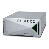
PI5310
PICARRO PI5310 Manuals
Manuals and User Guides for PICARRO PI5310. We have
2
PICARRO PI5310 manuals available for free PDF download: User Manual
PICARRO PI5310 User Manual (174 pages)
For N2O, CO, H2O
Brand:
PICARRO
| Category:
Measuring Instruments
| Size: 14 MB
Table of Contents
Revision History
2
Table of Contents
4
List of Figures
9
List of Tables
12
Introduction
13
System Overview
13
Analyzer
13
Figure 1 - PI5310 Front/Back Panels
13
Front Panel Operating Status
14
A2000 Vacuum Pump
14
Analyzer Specifications
14
Figure 2 - LED Status Indicator
14
Figure 3 - A2000 Vacuum Pump - Side Views
14
Table 1 - PI5310 Specifications
14
Acronyms
16
Table 2 - Acronyms, Formulas, Units, and Symbols
16
Text Conventions
19
Safety
20
Warning Symbols
20
General Safety
21
CDRH Certification
21
CE Certification
21
Laser Safety
23
Figure 4 - Laser Safety Label - Affixed to Outside Cover of Analyzer
23
Figure 5 - Laser Safety Label - Affixed to Inside of Analyzer
24
Unpacking
25
Inspect the Shipping Containers
25
Unpack Components
25
Figure 6 - Shipping Container with Clamps Installed/Removed
25
Contents
26
Table 3 - Shipping Contents
26
Hardware Setup
29
Required Components and Tools
29
Installation Safety
29
Analyzer Preparation
32
Ventilation Considerations
32
Positioning
32
Set A2000 Pump Input Voltage
33
A2000 Pump and Gas Inlet Connections
33
Pump Connections
33
Figure 7 - Vacuum Pump Voltage Selection
33
Sample Gas Inlet Connections
34
Figure 8 - Analyzer Setup with A2000 Pump
34
Sample Gas Inlet Connection (SST Tubing)
35
Sample Gas Inlet Connection (PFA Tubing)
35
Figure 9 - Orientation of Inlet Nut and Ferrules (SST Tubing)
35
Figure 10 - Orientation of Inlet Nut and Ferrules (PFA Tubing)
35
Rack Mount Instructions
36
Rack Mount (Slide Rails)
36
Figure 11 - Inner Rail Slide Removal
37
Figure 12 - Attaching Inner Slide Rails to Analyzer
37
Figure 13 - Front Panel Restraint Installed
38
Figure 14 - Outer Rail Mounted to Rack
38
Rack Mount (Mount Kit)
39
Electrical Connections
40
Figure 15 - Front Panel Restraint Installed
40
Figure 16 - Rear Panel Diagram
41
Chiller Laser Cooling
42
Chiller Setup
42
Figure 17 - Reservoir Connections at Time of Shipment
43
Figure 18 - Reservoir Inspection
44
Figure 19 - Reservoir Coolant Level
44
Figure 20 - Reservoir Connected and Ready to Run
45
Figure 21 - Confirmation of Coolant Flow
45
Chiller Maintenance
46
Analyzer Basic Operation
48
Startup
48
Shutdown
49
Figure 22 - CRDS Data Viewer Screen
49
Figure 23 - Stop Data Acquisition Confirmation
50
Analyzer Restart after Electrical Power Outage
51
Picarro Launch Pad
51
Home Menu
51
Figure 24 - Picarro Launch Pad/Home Menu
52
Tools Menu
53
Figure 25 - Picarro Launch Pad/Tools Menu
53
Settings Menu (Setup Tools)
54
Administration Menu
54
Figure 26 - Transfer Files Dialog
54
Language Selector
55
Figure 27 - Picarro Launch Pad/Administration Menu
55
Zoom Level
56
Figure 28 - Language Selector
56
Figure 29 - Language Change Confirmation
56
Figure 30 - Picarro Launch Pad - Zoom Level
57
GUI Functions
58
GUI Overview
58
Figure 31 - CRDS Data Viewer GUI
58
Users, View, Tools, and Help Menus
59
User Menu
59
View Menu
59
Figure 32 - CRDS Toolbar Options
59
Tools Menu
60
Help Menu
60
Alarms Panel
60
Figure 33 - Configure Graph Window
60
Figure 34 - Alarm Panel
61
Digital Readouts
62
Figure 35 - Alarm Set Dialog
62
Instrument Status
63
Quit Button
63
Figure 36 - Digital Readouts Panel
63
Figure 37 - Instrument Status Panel
63
Figure 38 - CRDS Quit Button
63
Restart User Log(S) Button
64
Data Log Filename and Path
64
Data Window
64
Figure 39 - Restart User Logs Button
64
Figure 40 - Data Log Filename and Path Panel
64
Data Source and Data Key Pull down Menus
65
Figure 41 - Data Window Panel
65
Figure 42 - Data Source and Data Key Pull down Menus
65
6.10 Precision Pulldown Menu
66
6.11 Measurement Status Log
66
6.11.1 Common Status Log Messages
66
Figure 43 - Precision Pull-Down Pane
66
Figure 44 - Measurement Status Log
66
6.12 Reset Buffers Button
67
6.13 Graph Zooming and Panning
67
6.13.1 Zooming In/Out
67
Figure 45 - Data Graph Zoom Function
67
6.13.2 Lock/Unlock Time Axis
68
6.13.3 Panning
68
Figure 46 - Auto-Scale Buttons
68
User Management
69
Overview
69
Table 4 - User Accounts and Functions
69
Managing User Accounts
70
Figure 47 - User Management Window
70
Changing a User Password
71
Figure 48 - Change Password
71
Changing a User's Role
72
Figure 49 - Change Roles
72
Disabling a User Account
73
Adding a User
73
Figure 50 - Disable Users
73
Setting User Policies
74
Figure 51 - Add User
74
User Policy Descriptions
75
Figure 52 - User Policies Tab
75
Table 5 - User Policies
75
Viewing User History
76
Figure 53 - User History Tab
76
Viewing My Profile
77
Figure 54 - My Profile Tab
77
File Management
78
Data Archive
78
Data File Name
78
File Archiving
79
Figure 55 - Example Data File Name
79
Modbus Communication
81
Configuring Modbus Communication
81
Figure 56 - Settings/Modbus Configuration
81
Modbus Data Registers Overview and Setup
82
Figure 57 - Modbus Settings Window
82
Table 6 - MODBUS Register Types
82
Modbus TCP Setup Notes
83
Modbus RTU Setup Notes
83
Modbus Register Maps
83
Input Register Map
83
Table 7 - Input Registers
83
Discrete Input Register Map
86
Table 8 - Discrete Input Registers
86
Holding Register Map
88
Table 9 - Holding Registers
88
Coil Register Map
89
Table 10 - Coil Register Map
89
Troubleshooting
92
10.1 Power LED on Analyzer Does Not Illuminate
92
Sample Pressure Not Controlled to Appropriate Value for Concentration Measurements
92
Maintenance
93
11.1 Service Plans
93
11.2 Particulate Filter Replacement
93
11.2.1 Symptoms of a Clogged Filter
94
11.2.2 Solutions for Water Incursion
94
11.2.3 Required Parts and Tools
94
11.2.4 Pressure Inlet Port Particulate Filter Replacement
94
Figure 58 - Pressure Inlet Port
95
Figure 59 - Pressure Inlet Filter - Removed
95
Figure 60 - Removing Filter from Pressure Inlet Bulkhead
96
Figure 61 - Filter Removed from Pressure Inlet Bulkhead
96
11.2.5 CPU Fan
97
11.2.6 A2000 Pump Rebuild Kit
97
Figure 62 - Tightening the Filter Fittings
97
11.3 Cleaning and Decontamination
98
Transportation and Storage
99
12.1 Shutdown and Preparation
99
Figure 63 - Stop Data Acquisition/Shutdown
99
12.2 Packing
100
Figure 64 - Reduce Moisture Content/Shutdown
100
A Setup Tools and Communication
101
Analyzer Settings and Tools
101
Figure 65 - Analyzer Setup Tools
101
Serial Port
102
Figure 66 - Serial Port Settings
102
Port Manager
103
Command Interface - Specifying Digital Data Output
103
Figure 67 - Serial/Socket Port Manager Settings
103
Command Interface - Specifying Digital Data Output
104
Figure 68 - Command Interface Settings
104
Data Logger
105
Figure 69 - Data Streaming Settings
105
Figure 70 - Data Logger Setup Settings
106
Serial Communication
107
Remote Data Access
107
Ntp
108
Email
108
B Alarm Status
109
Table 11 - Alarm Status Bit Assignment
109
Table 12 - Alarm Status Definitions
109
C Data Log Columns
110
Table 13 - PI5310 Data Log Columns
110
D Enabling/Disabling Data Output
116
E Analog Current Signal Output
117
Connecting the 4-20Ma Signal Output
117
Figure 71 - 4-20 Ma Output with Terminal Connector
117
Table 14 - Signal Output Settings
117
Figure 72 - Removing the Terminal Connector
118
Figure 73 - Terminal Connector Retaining Screws
118
Data File Viewer
119
Quick Start Guide
119
Figure 74 - Batch Convert DAT to H5 - Navigation
119
Figure 75 - Selecting Variables for Concatenation
120
Figure 76 - Concatenated Output .H5 Filename
120
Data File Viewer Overview
121
Figure 77 - Time Series Selection Options
121
File Menu
122
Figure 78 - Picarro Data File Viewer - File and New Menus
122
Figure 79 - Select Variable Form
123
Figure 80 - Define Date Range Dialog
124
Figure 81 - File Structure of Data File Viewer
125
New - Time Series Plot
127
Figure 82 - Time Series Viewer
127
Time Series Viewer Menus
128
Save Configuration
128
Figure 83 - Time Series Viewer Menus
128
Figure 84 - Time Series Viewer - File Menu
128
Figure 85 - Time Series Viewer - Feature Capture
128
Take Screenshot
129
Time Series Viewer Analysis Menu
129
Figure 86 - Time Series Viewer - Analysis Menu
129
Time Series Viewer View Menu
130
Figure 87 - Histogram Window
130
The Time Series Viewer Canvas
131
Figure 88 - Time Series Viewer - View Menu
131
Figure 89 - Time Series Viewer Canvas
132
Figure 90 - Canvas Right-Click Pop-Up Menu
133
Figure 91 - Time Series Viewer Image Editor
133
Figure 92 - Time Series Viewer Dataset Options
134
Fitting Menu
135
Figure 93 - Correlation XY Plot
135
Analysis Menu
136
Figure 94 - Fitting Menu
136
Figure 95 - Analysis Menu
136
Figure 96 - Results of Quadratic Fitting
136
G Setting up Contained Exhaust Flow
137
Tools and Parts Required
137
Directions
137
Figure 97 - A2000 Pump Vacuum and Exhaust Ports
137
Figure 98 - Pump Noise Dampener Removal
138
Figure 99 - Pump Exhaust Line Adapter Fittings
138
H External Valve Sequencer
140
Introduction
140
A0311 16-Port Distribution Manifold
140
Compatibility
140
Function
140
A0311-S 16-Port Distribution Manifold (Silco)
141
Compatibility
141
Function
141
Figure 100 - A0311 - 16-Port Distribution Manifold
141
Figure 101 - A0311-S - 16-Port Sequencer - Fast Multiport Gas Sampler
141
Setting up Solenoid Valves
142
Setting up a Rotary Selector Valve
142
External Valve Sequencer Software Overview
142
Opening the Sequencer
142
Valve Sequencer UI Menus
143
Figure 102 - Launching the Valve Sequencer GUI
143
Figure 103 - Valve Sequencer UI Dropdown Menus
143
Figure 104 - External Valve Sequencer UI
144
Programming and Saving a Valve Sequence
145
Figure 105 - Example 15 Minute Sequence
146
Loading and Running a Saved Sequence
147
Loading a Saved Sequence
147
Running a Sequence
147
Skipping Steps or Advancing to a Particular Step
147
Stopping the Sequencer
147
Resetting Valves
148
Valve Sequencer Data Records
148
Figure 106 - Data Logger Service Mode
149
Scheduling a Sequence
150
I Introduction to Technology
151
Cavity Ring-Down Spectroscopy (CRDS)
151
Relating Ring-Down Time to Absorption Intensity
152
Figure 107 - Schematic of the Picarro CRDS Analyzer Cavity
152
Converting Absorption Intensity to Concentration
153
Figure 108 - Light Intensity as a Function of Time in a CRDS System
153
Spectral Precision and High Sensitivity Measurements
154
Figure 109 - Absorption Spectral Curve
154
JSDS for Koolance LIQ-702
156
Limited Warranty
172
Product Support
174
Advertisement
PICARRO PI5310 User Manual (161 pages)
Analyzer for N2O, CO, H2O
Brand:
PICARRO
| Category:
Measuring Instruments
| Size: 9 MB
Table of Contents
Picarro Notices
2
Table of Contents
3
List of Figures
7
List of Tables
11
Introduction
12
Intended Use
12
System Overview
12
Figure 1: PI5310 Front/Back Panels
12
Analyzer Specifications
13
Figure 2: PI5310 LED Status Indicator
13
Figure 3: A2000 Vacuum Pump - Side Views
13
Table 1: PI5310 Specifications
13
Acronyms
15
Table 2: Acronyms, Formulas, Units, and Symbols
15
Text Conventions
17
Safety
18
Warning Symbols
18
Table 3: Warning/Information Icon Types
18
General Safety
19
Laser Safety
20
Figure 4: Laser Safety Label - Affixed to Outside Cover of Analyzer
20
Figure 5: Laser Safety Label - Affixed to Inside of Analyzer
21
Unpacking
22
Inspect the Shipping Container
22
Figure 6: Shipping Container with Clamps Installed/Removed
22
Unpack Components
23
Figure 7: PI5310 Shipping Box Contents
23
Table 4: PI5350: Shipping Container Contents
24
Hardware Setup
25
Items/Tools Required
25
Installation Safety
25
Analyzer Preparation
27
Ventilation Considerations
27
Connections - A2000 Pump and Gas Inlet
28
Figure 8: Vacuum Pump Voltage Selection
28
Figure 9: Analyzer Setup with A2000 Pump
29
Figure 10: Orientation of Inlet Nut and Ferrules (SST Tubing)
30
Rack Mount Instructions
31
Figure 11: Orientation of Inlet Nut and Ferrules (PFA Tubing)
31
Figure 12: Inner Rail Slide Removal
32
Figure 13: Attaching Inner Slide Rails to Analyzer
32
Figure 14: Locking Bracket Installed
33
Figure 15: Outer Rail Mounted to Rack
33
Electrical Connections
34
Figure 16: Annotated Rear Panel Diagram
34
Chiller Laser Cooling
35
Chiller Setup
36
Figure 17: Reservoir Connections at Time of Shipment
36
Figure 18: Reservoir Inspection
37
Figure 19: Proper Coolant Level in Reservoir
37
Figure 20: Reservoir Connected and Ready to Run
38
Figure 21: Confirmation of Coolant Flow
38
Chiller Maintenance
39
Analyzer Basic Operation
40
Startup
40
Shutdown
42
Figure 22: Gui/Data Viewer Screen
42
Figure 23: Analyzer Shutdown Dialog
43
Analyzer Restart after Electrical Power Outage
44
Picarro Launch Pad
44
Figure 24: Picarro Launch Pad/Loading Screen
44
Figure 25: Picarro Launch Pad/Home Menu
45
Figure 26: Transfer Files Dialog
46
Figure 27: the Config Login Dialog
47
Figure 28: Configuration Menu
47
Figure 29: Login: Network Settings Tool
48
Figure 30: Network Settings Tool
48
Figure 31: Clock Set Dialog
49
Figure 32: Clock Set Menu
50
Figure 33: Clock Set Dialog
50
Service Menu
51
List of GUI Functions
52
GUI Overview
52
Figure 34: Layout of PI5310 Analyzer GUI
52
Users, View, Tools, and Help Menus
53
Figure 35: CRDS Toolbar Options
53
Alarms Panel
54
Figure 36: Alarm Panel
54
Digital Readouts
55
Figure 37: Alarm Set Dialog
55
Instrument Status
56
Figure 38: Digital Readouts Panel
56
Figure 39: Instrument Status Panel
56
Shutdown and Stop User Log(S) Buttons
57
Figure 40: Shutdown/Stop User Log
57
Quit Button
57
Figure 41: Data Log Filename and Path Panel
57
Data Window
57
Data Source and Data Key Pull down Menus
58
Figure 42: Data Window Panel for N O, CO, and H O
58
Precision Pulldown Menu
59
Analyzer Status Log
59
Figure 43: Data Source and Data Key Pull down Menus
59
Figure 44: Precision Pull-Down Pane
59
Data Buffer Level Meter
60
Figure 45: Analyzer Status Log
60
Figure 46: Data Buffer Level Meter and Reset Buffers Button
60
Reset Buffers Button
61
Graph Zooming and Panning
61
Zooming In/Out
61
Figure 47: Data Graph Zoom Function
61
Figure 48: Auto-Scale Buttons
61
User Management
63
Overview
63
Table 6: User Accounts/Functions
63
Managing User Accounts
64
Figure 49: User Management/User Accounts Tab
64
Changing a User Password
65
Figure 50: Change Password
65
Figure 51: Change Roles
66
Disabling a User Account
66
Figure 52: Disable Users
67
Adding a User
67
Figure 53: Add User
67
Setting User Policies
68
Figure 54: User Policies Tab
68
Table 7: User Policies
69
Viewing User History
70
Figure 55: User History Tab
70
File Management
71
Data Archive
71
Data File Name
72
File Archiving
72
Figure 56: Example Data File Name
72
Modbus Communication
74
Configuring Modbus Communication
74
Figure 57: Settings/Modbus Configuration
74
Figure 58: Modbus Settings Window
75
Modbus Data Registers Overview and Setup
76
Modbus Register Maps Overview
76
Table 8: MODBUS Register Types
76
Input Register Map
77
Table 9: Input Registers
77
Discrete Input Register Map
79
Table 10: Discrete Input Registers
79
Holding Register Map
80
Table 11: Holding Registers
80
Coil Register Map
81
Table 12: Coil Register Map
81
Serial Communication
84
Figure 59: Default Serial Port Configuration
84
COM1 (Command Interface) Protocol
85
Figure 60: Data Output Example
85
COM2 (Data Manager) Data Streaming Protocol
86
Figure 61: Data Streaming Output
86
Troubleshooting
87
Power LED on Analyzer Does Not Illuminate
87
Sample Pressure Not Controlled to Appropriate Value for Concentration Measurements
87
Maintenance
88
Service Plans
88
Particulate Filter Replacement
88
Required Parts and Tools
89
Figure 62: Pressure Inlet Port
90
Figure 63: Pressure Inlet Filter Assembly - Removed from Housing
90
Figure 64: Removing Filter from Pressure Inlet Bulkhead
91
Figure 65: Filter Removed from Pressure Inlet Bulkhead
91
Figure 66: Tightening the Filter Fittings
92
Figure 67: Sample Inlet Port
92
Figure 68: Sample Filter Assembly - Removed from Housing
93
Figure 69: Removing Filter from Sample Inlet Bulkhead
93
Figure 70: Filter Removed from Sample Inlet Bulkhead
93
Cleaning and Decontamination
94
Transportation and Storage
95
Shutdown and Preparation
95
Packing
95
Figure 71: Stop Data Acquisition/Shutdown
95
APPENDIX A - Alarm Status
96
Table 13: Alarm Status Bit Assignment
96
Table 14: Alarm Status Definitions
96
APPENDIX B - Data Log Columns
97
Table 15: PI5310 Data Log Columns
97
APPENDIX C - Enabling/Disabling Data Output
103
APPENDIX D - Analog Current Signal Output
104
Figure 72: 4-20 Ma Output with Terminal Connector in Place
104
Connecting the 4-20Ma Signal Output
105
Figure 73: Removing the Terminal Connector
105
Figure 74: Terminal Connector Retaining Screws
105
APPENDIX E - Data File Viewer
106
Quick Start Guide
106
Figure 75: Batch Convert DAT to H5 - Navigation
106
Figure 76: Selecting Variables for Concatenation
107
Figure 77: Concatenated Output .H5 Filename
108
Figure 78: Time Series Selection Options
108
Data File Viewer Overview
109
Figure 79: Picarro Data File Viewer - File Menu
109
File Menu
109
Load Config
109
New Menu
110
Figure 80: Picarro Data File Viewer - New Menu
110
Figure 81: Select Variables Form
111
Figure 82: Define Date Range Dialog
112
Figure 83: File Structure of Data File Viewer
112
New - Time Series Plot
115
Time Series Viewer Menus
115
Figure 84: Time Series Viewer
115
Figure 85: Time Series Viewer - File Menu
116
Save Configuration
116
Figure 86: Time Series Viewer - Feature Capture
116
Take Screenshot
116
Figure 87: Time Series Viewer - Analysis Menu
117
Figure 88: Histogram Window - CO
117
Figure 89: Time Series Viewer - View Menu
118
Figure 90: Time Series Viewer Canvas
119
Right-Click Menu
119
Figure 91: Canvas Right-Click Pop-Up Menu
119
Figure 92: Image Editor Form
120
Figure 93: Time Series Viewer Dataset Options
121
Figure 94: Correlation XY Plot
122
Figure 95: Fitting Menu
123
Figure 96: Analysis Menu
123
Figure 97: Results of Quadratic Fitting
124
APPENDIX F - Setting up Contained Exhaust Flow
125
Introduction
125
Tools and Parts Required
125
Figure 98: A2000 Pump Vacuum and Exhaust Ports
125
Directions
126
Figure 99: Pump Noise Dampener Removal
126
Figure 100: Pump Exhaust Line Adapter Fittings
126
APPENDIX G - External Valve Sequencer
127
Introduction
127
A0311 16-Port Distribution Manifold
127
A0311-S 16-Port Distribution Manifold (Silco)
128
Figure 101: A0311 - 16-Port Distribution Manifold
128
Valve Control Configurations
129
Setting up Solenoid Valves
129
Figure 102: A0311-S - 16-Port Sequencer - Fast Multiport Gas Sampler
129
Setting up a Rotary Selector Valve
130
External Valve Sequencer Software Overview
130
Figure 103: Launching the Valve Sequencer GUI
131
Figure 104: Valve Sequencer UI Dropdown Menus
131
Figure 105: External Valve Sequencer UI
132
Programming and Saving a Valve Sequence
133
Figure 106: Example 15 Minute Sequence
134
Loading and Running a Saved Sequence
135
Scheduling a Sequence
136
APPENDIX H - Relative Humidity Conversion
137
APPENDIX I - Introduction to CRDS Technology
138
APPENDIX I - Introduction to CRDS
138
Cavity Ring-Down Spectroscopy (CRDS)
138
Relating Ring-Down Time to Absorption Intensity
139
Figure 107: Schematic of Picarro CRDS Analyzer Cavity
139
Converting Absorption Intensity to Concentration
140
Figure 108: Light Intensity as Function of Time in CRDS System
140
Spectral Precision and High Sensitivity Measurements
141
Figure 109: Absorption Spectral Curve
141
APPENDIX J - SDS for Koolance LIQ
143
APPENDIX K - Limited Warranty
159
About Picarro
161
Product Support
161
Advertisement
Related Products
PICARRO PI5000 Series
PICARRO PI2114
PICARRO PI2000 Series
PICARRO G2000 Series
PICARRO G2103
PICARRO G2106
PICARRO G2107
PICARRO G2108
PICARRO G2114
PICARRO G2123
PICARRO Categories
Measuring Instruments
Laboratory Equipment
Water Pump
Digital Manifolds
Samplers
More PICARRO Manuals
Login
Sign In
OR
Sign in with Facebook
Sign in with Google
Upload manual
Upload from disk
Upload from URL