Do you have a question about the Xe-50M and is the answer not in the manual?
Questions and answers
Mark
March 27, 2025
is there a way to test this controller mine is not functioning
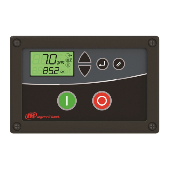
Xe-50m
is there a phone to call I'm old and prefer phone calls to emailing
1 comments:
Mr. Anderson
March 27, 2025
To test an Ingersoll-Rand Xe-50M controller that is not functioning, follow these steps using the available information:
1. Check Power Supply: Ensure the controller is receiving power. If not, inspect the voltage transformer and power connections.
2. Verify Motor Rotation: If the controller shows "Ck Motor Rot", check that the motor is rotating correctly. Correct rotation is confirmed when the sump pressure reaches 1 psi or more within 3 seconds of starting (6 seconds for soft starters or if the temperature is below 50°F).
3. Check for Overload: If the display shows "Overload", inspect the motor and fan overload relays. A trip occurs if the relay is open for at least 3 seconds.
4. Remote Stop Issue: If "Rem Stop Fail" appears, confirm that the remote stop/start option is properly configured and the stop button is not stuck in the open position.
5. Inspect Communication Connections: If connecting to a MODBUS network, ensure RS-485 cables are correctly connected to port X04 and properly shielded and routed to avoid electrical interference.
If these checks do not identify the issue, further diagnostics or professional service may be needed.


Need help?
Do you have a question about the Xe-50M and is the answer not in the manual?
Questions and answers
is there a way to test this controller mine is not functioning Xe-50m is there a phone to call I'm old and prefer phone calls to emailing
To test an Ingersoll-Rand Xe-50M controller that is not functioning, follow these steps using the available information:
1. Check Power Supply: Ensure the controller is receiving power. If not, inspect the voltage transformer and power connections.
2. Verify Motor Rotation: If the controller shows "Ck Motor Rot", check that the motor is rotating correctly. Correct rotation is confirmed when the sump pressure reaches 1 psi or more within 3 seconds of starting (6 seconds for soft starters or if the temperature is below 50°F).
3. Check for Overload: If the display shows "Overload", inspect the motor and fan overload relays. A trip occurs if the relay is open for at least 3 seconds.
4. Remote Stop Issue: If "Rem Stop Fail" appears, confirm that the remote stop/start option is properly configured and the stop button is not stuck in the open position.
5. Inspect Communication Connections: If connecting to a MODBUS network, ensure RS-485 cables are correctly connected to port X04 and properly shielded and routed to avoid electrical interference.
If these checks do not identify the issue, further diagnostics or professional service may be needed.
This answer is automatically generated