Table of Contents
Advertisement
Advertisement
Table of Contents

Related Manuals for Ingersoll-Rand Xe-90M


Summary of Contents for Ingersoll-Rand Xe-90M
- Page 1 Control Systems Xe-90M/145M R & RS Series Fixed Speed Technician’s Pocket Guide...
- Page 2 About this Pocket Guide This pocket guide was created to assist Field Service Technicians when troubleshooting warnings, alarms within the R-Series/RS-Series machines. For detailed information of the controller, such as: navigation keys, controller display layout, installation info, and basic operation download in Passport the following PDF files: Product information manuals: R37-160kW: CCN 80446164...
-
Page 3: Table Of Contents
Table of Contents Description Pages Controller Introduction Main Customer’s Power Supply Fuse Designation for R & RS-Series T1 Transformer & Control Voltage 115 VAC Quick Disconnect Plugs/Connectors 9-10 P1 Triac Outputs 11-30 P2 Relay Outputs 31-32 P3 Digital Inputs 33-38 P4 Outputs Digital-Analog Outputs 39-40 P5 Analog Pressure Sensor Inputs... -
Page 4: Controller Introduction
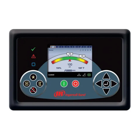
CONTROLLER INTRODUCTION The Xe-90M/145M control system provides efficient and reliable compressor operation. The controller supports thirty languages, independently configurable units of measure as well as enhanced network and communication capabilities. This microprocessor-based controller uses a finger touch membrane for operation of the compressor and setting control parameters. - Page 5 The major components of the control system include the controller, voltage transformer, and solenoid valves to control compressor operation. A series of pressure sensors, temperature sensors, relays, and switches make up the instrumentation that provides feedback to the controller. Operating and navigating the controller is easy and intuitive through a series of folders and pages within the graphical user interface (GUI).
-
Page 6: Main Customer's Power Supply
Customer’s Main Power Supply The customer is responsible for correctly sizing and installing the Main Fuse Protection. This is intended to protect the machine during an overcurrent condition. These fuses should be time-delay in order to accommodate the inrush current at machine startup. For an instant, the inrush current drawn by the machine can be several times greater than the full-load rating. -
Page 7: Fuse Designation For R & Rs-Series
Fuse Designation for R & RS-Series Always use local electrical code or National Electrical Code manual (NEC) to size fuses. FU 1, 2, 3 RS-Series Fan Drive Fuses Fuses are required when the Low ambient option is installed in the machine. FU1, 2, & 3 Fast Acting Class- J fuses protect the Fan Drive (FD) in single stage units. - Page 8 575VAC/60Hz. Dryer option at 208VAC/60HZ and 575VAC/60Hz. RS200-250kW FU 4, 5, 6: This machine uses two Fan Drives FD1 and FD2 when the Low Ambient Option is installed. The Fast Acting Class-J fuses protecting FD2 are FU4, 5, 6. FU7, 8, 9 R-Series Dryer Fuses (S-S) Fuses are required when the Dryer option is installed.
-
Page 9: T1 Transformer & Control Voltage 115 Vac
T1 Transformer & Control Voltage 115 VAC T1 - Control Transformer T1 is the schematic designation of the control transformer. A step-down transformer (T1) reduces the incoming line voltage to levels suitable for use with the Xe control system. The reduced voltage sources are called secondary circuits. -
Page 10: Quick Disconnect Plugs/Connectors
Quick Disconnect Plugs/Connectors *Also known as Phoenix connector A group of differently sized terminal plugs is used to connect control and instrument wires to the controller. These connectors are female Phoenix type (5.08mm spacing) and plug into matching male receptacles on the controller. - Page 11 How can I check the quick disconnect plugs? *Ensure cables are properly installed in the terminals before replacing components Perform a quick test with a paper clip if faulty signals are suspected. Replace quick disconnect plug if the tension retainer is defective when tested.
-
Page 12: P1 Triac Outputs
P1 –Triac Outputs Terminal plug strip P1 is dedicated to outputs that provide control of solenoid valves and starter contactors. These outputs are powered by 115VAC located at P1‐ 1.The 115VAC circuit passes through MCB3 circuit breaker and ES-1 contact with “hot” wire 102 connecting to P1‐1 and the Neutral wire connecting to P1‐10. - Page 13 R-Series P1 Triac...
- Page 14 RS-Series P1 Triac 115VAC...
- Page 15 Terminal Description & Terminal Connection Terminal Description R-Series RS-Series Control Voltage 110-120 VAC P1-1 P1-1 Contactor KM1 & KM2 P1-2 P1-2 Contactor KM3 P1-3 P1-3 Fan Motor Contact KM4 P1-4 P1-4 Load Solenoid 1SV P1-5 P1-6 Modulation Solenoid 5SV P1-6 P1-7 Isolation Solenoid Valve 7SV P1-6...
- Page 16 The following section explains the components of the Starter System: Contactors KM1 & KM2 The controller provides power to KM1 and KM2 main motor starter coils to load and unload the unit under normal operation. The controller applies 115VAC to the coil of the contactors at A1-A2 terminals, causing the contactor to "pull in"...
- Page 17 Fan Motor Contactor KM4 Connected to P1-4, the controller provides 115VAC to KM4 fan motor starter coil at start up. KM4 provides control of the cooling fan motor starting circuit. The Fan Motor Protection (FMP) is explained next. FMP – Fan Motor Protection The Fan Motor Protection overload is a normally open contact that closes when the Fan...
- Page 18 1SV Load Solenoid Valve (N.C) Connected to P1, the controller provides power to the 1SV load solenoid valve. When energized, 1SV opens and applies pressure to the load cylinder, allowing the inlet valve to open and the compressor to load. 1SV remains closed/de-energize when the machine is unloaded, auto restart, or OFF.
- Page 19 7SV Isolation Solenoid Valve for RS-series 7SV assists the load solenoid 1SV to overcome the modulation pressure regulator output and allow the inlet valve load cylinder to actuate. TR Timing Relay for RS-Series TR creates a 2-second delay when powering the 5SV modulation solenoid.
- Page 20 CDE1 Condensate No Loss Drain Connected to P1 Triac 115 VAC to release the condensate water from the moisture separator. The No-Loss Drain valve is also capable to send a warning status to the controller P3 terminal under abnormal conditions. Note: CDE2 &...
- Page 21 K2 Phase Monitor Relay (Optional) An optional phase monitor can be installed to protect the motor and control system against phase imbalance. The phase monitor is connected to the Incoming Power feed through circuit breaker MCB2 (designated as K2‐1 in the Electrical Schematic). The phase monitor will open cables 102 and 105 (K2-1) removing power from P1-1 Triac voltage.
- Page 22 K3 Blower Drive Control Relay At startup, the machine energizes K3 relay through P1 terminal closing the run signal for the Blower Drive (FD) terminals 12, 18 and 27 (K3-1). *K3-1 run signal for the Blower Drive or Dryer option.
- Page 23 K3 Dryer Run Relay R-Series The run signal is also used as the dryer run contact for R-series machines with the Dryer option installed (for RS-Series, the run signal of the Dryer energizes through K5 relay). K5 Dryer Run relay for RS-Series At start-up, the controller energize K5 relay closing the run signal K5-1 allowing the Dryer Main Contactor KM5 &...
- Page 24 RTD Main Motor Monitor for RS-Series (option) RTD main motor monitoring is an optional feature connected to the PSU Power supply 24VDC. The main purpose is to monitor the temperatures of the motor bearings and the stator windings via the Modbus port in P9 7-8.
- Page 25 K6 PORO relay for RS-Series A relay connected to P4 1- 2 terminals controls the PORO horn in the Triac 115 VAC cables 121 hot/150 common-ground. Note: the function of the PORO horn for R & RS- Series are explain in “PORO Power Outage Restart Option”...
- Page 26 R-Series PORO: energized by P1-9 Triac voltage. Option needs to be install in the controller Tech Note 207. RS-Series PORO: close by K6 relay in P4 terminal allowing P1 Triac voltage to energize the PORO horn. explain in this section) *PORO Field Installation Kit found in Passport.
- Page 27 MCB2 Phase Monitor Main Circuit Breaker MCB2 protects K2 Phase Monitor and, in case of a low voltage condition, opens the control voltage to the controller terminal P1-1. Cables used to open the connections are 102-105. MCB3 Control Voltage Circuit Breaker MCB3 is a circuit breaker in the 110/120 VAC secondary side of the control transformer circuit to provide a degree of...
- Page 28 display and logic at terminal P10 1(N)-2(L). The PSU must be grounded to the starter box chassis. *Green LED light indicates Power available to PSU Arc Suppressors (RC) Suppress the arc created when the contactor coils are energized. If not installed, the arc created by the coils can create nuisance faults in the 5 VDC circuits.
- Page 29 ES-2) that open when the red E- Stop button is pressed. Refer to the electrical schematics for the correct terminal location. ES-1 contact (red wires) is located just after MCB3 in the 115 VAC circuit and connects to terminal P1-1 ES-2 contact (blue wires) is located in the 24 VDC logic circuit at P3 7-8 for R-Series or P3 1-2 for RS-Series.
- Page 30 Main Motor Overload Relay (FR1) Connected to the bottom of KM1, the main motor overload relay provides protection in the event of an overcurrent condition in the motor windings. It is adjustable per the nominal current and service factor values found on the motor data tag. For Settings see Tech Note FR1 is normally closed and sends a trip signal to the controller P3 terminal, opening the digital signal at...
- Page 31 the compressor down alarming in “Control Power Loss”, if Control Power Loss set point is enabled in Factory Settings. Note: A shorted 1ATS switch can cause the MCB3 breaker to open when power is applied to the machine or start button is pressed. *Switch available for 2-stage units...
-
Page 32: P2 Relay Outputs
P2 Relay Outputs Terminal plug strip P2 is dedicated to outputs that provide dry contacts for remote warning and trip notification. P2 contains 2 outputs rated at 250VAC, 48-62Hz, 3 Amps. Relay outputs (P2) information found on the back of the controller. *Electrical Schematic for R &... - Page 33 CWO-Common Warning Outputs N.O connected at P2‐4 Common P2-2 N.C connected at P2‐6. What is a dry contact? Also called voltage free contact. The purpose is to close or open P2 terminals, without changing the primary voltage applied to the controller, allowing the customer to monitor the running status of the machine.
-
Page 34: P3 Digital Inputs
P3 Digital Inputs Terminal plug strip P3 is dedicated to digital inputs that provide remote control and feedback from various switches installed on the package, like motor overload/fan motor overload. R-Series RS-Series... - Page 35 LED 12 serves as a digital input short notification. See Tech Note 8089 for more information. P3 also has Red LED (LED12) that comes on if any of the digital input connections from P3 are shorted to earth ground. The LED is at lower left corner just to left of "1"...
- Page 36 P3 Inputs Terminal Description R-Series RS-Series *Inputs to controller and normal state of components. Emergency Stop Close P3 7-8 Close P3 1-2 Main Motor Overload Close P3 11- Close P3 3-4 Fan Motor Protector Close P3 13- Close P3 5-6 Dryer High Pressure Switch Close P3 15- Close P3 21-...
- Page 37 *Emergency Stop, Main Motor Overload, and Fan Motor Protection devices are explained in section P1 Triac Outputs. Dryer High Pressure Switch (DHP) On units with an integrated dryer, if the dryer high pressure switch opens while the dryer is running, a fault is sent to the controller P3 terminal.
- Page 38 Remote Stop (RSP) The remote stop button is intended to stop the compressor remotely. The normally closed contact is connected to P3 terminal. The switch must be closed when the unit is attempted to start remotely. This is an option that can be installed by the customer. Remote Start (RST) The remote start button is intended to start the compressor remotely.
- Page 39 from a remote location. The normally closed contact is connected to the controller P3 terminal. This is an option that can be installed by the customer. Remote Load/Unload (RLU) The remote Load/Unload is a normally open switch used control the Load/Unload function for the compressors from a remote location.
-
Page 40: P4 Outputs Digital-Analog Outputs
P4 – Digital and Analog Outputs Digital and Analog outputs are used for a variety of Reasons. Two example are the stepper motor and variable speed drive control. Depending on the machine type, one or more outputs can be connected to the controller. The controller has four digital and two analog outputs located at terminal plug strip P4. - Page 41 Test on blower speed signal Tech Tube 10968. *Machines with Low Ambient option installed.
-
Page 42: P5 Analog Pressure Sensor Inputs
P5 Analog Pressure Sensor Inputs Pressure transducers are used to convert air pressure signals to voltage signals between 0.5 and 4.5 Volts How a pressure transducer work? The transducer contains a metal diaphragm connected to a small piece of steel called the beam. The beam is attached to a strain gauge. - Page 43 directly proportional to pressure and follows a linear path throughout its range. The output signal is processed by an analog to digital converter within the controller. Depending on the voltage level, the controller may change the pressure reading displayed, load/unload the compressor, or possibly shut the compressor down.
- Page 44 Pressure Transducer Voltage Signals Note: The signal terminal takes the DC feedback from the pressure transducer and calculates the corresponding psi/bar value to be shown on the controller display.
- Page 45 P5 Pressure Inputs R-Series New RS-Series Terminal Description 1AVPT (0-15 PSIG/1.03 P5- 1, 2, 3 P5- 1, 2, 3 Bar) Inlet Vacuum 2APT (0-225 PSIG/15.51 P5- 19,20,21 P5 4,5,6 Bar) Inter stage Air Pressure (2-Stage) 3APT (0-225 PSIG/15.51 P5 4,5,6 P5 7,8,9 Bar) Sump Pressure 4APT (0-225 PSIG/15.51...
- Page 46 P5 Electrical Schematic Connection R-Series RS-Series 1AVPT Inlet Vacuum Connected to P5, 1AVPT has a range of 0 to 15 psi (0 - 1.03 Bar). The output signal to the controller is 0.5 VDC at 0 psi (0 Bar) and 4.5 VDC at 15 psi (1.03 Bar). Inlet vacuum differential pressure is monitored to ensure the inlet air filter health and the butterfly valve in the inlet valve assembly is open when the machine...
- Page 47 loads it will create a higher differential pressure at 1AVPT sensor causing the alarm High Inlet Vacuum). 2APT – Inter stage Air Pressure (Two-stage Only) Mounted between the first and second stage of the compressor Air End, 2APT ensures the male rotor of the second stage Air End is rotating when the machine is running loaded/unloaded.
- Page 48 3APT has an output signal range of 0 psi (0 Bar) at 0.5 VDC to 225 psi (15.51 Bar) at 4.5 VDC. 4APT - Package Discharge Pressure The controller monitors package discharge pressure in order to load or unload the compressor. 4APT is compared with the sump pressure to calculate separator element differential.
- Page 49 6CPT has an output signal range of 0 psi (0 Bar) at 0.5 VDC to 225 psi (15.51 Bar) at 4.5 VDC. 7APT – Package A/C Pressure (Dryer option) Mounted in the air system, just downstream of the aftercooler. Package A/C pressure is used with integrated dryers and monitors air pressure entering the dryer.
-
Page 50: P6 Analog Temp Sensor Inputs
P6 Analog Temp Sensor Inputs Temperature sensitive resistors called, thermistors, are used to monitor temperature changes at various points within the compressor package. They operate on a 5 volt DC circuit. How a thermistor work? As the temperature of the sensor changes the resistance through the sensor changes by a corresponding amount. - Page 51 How can I check a thermistor? Place the thermistor in cold water (of known temperature) and take an Ohm reading across the 2 wires. Do the same with hot water and compare the 2 values with the Thermistor Resistance Chart. *If the thermistor Ohm value does not match the expected value, it is defective.
- Page 52 P6 Thermistor Description & Connection Thermistor R-series RS-series Description 1ATT Package Inlet P6 17-18 P6 1-2 Temperature 2ATT Air End Discharge P6 3-4 P6 3-4 Temperature 2CTT Injected Coolant P6 1-2 P6 5-6 Temperature 3CTT Oil Cooler Out Temp P6 7-8 (Option) 4 ATT Package Discharge P6 5-6...
- Page 53 Thermistor Resistance Chart Temp Temp Temp Ohms Ohms Ohms ⁰F ⁰F ⁰F 33631 5241 1194 25988 4276 1014 20244 3507 865.2 15889 2894 12562 2400 636.9 10000 2001 549.7 8013 1677 476.1 6461 1412 413.9 *Chart not applicable for Oil Free RTD sensors (see Nirvana Oil Free/Sierra Manual).
- Page 54 *5DTT and 6DTT (option)
- Page 55 1ATT – Package Inlet Temperature Sensor Mounted at the inlet air ducting of the package, 1ATT monitors the temperature of the incoming air to the package. 1ATT has a range between -10°F (-23.33°C) and 250°F (121.1°C). The output voltage is 0.5 volts DC at 0°F to 4.5V DC at 246°F (118.9°C).
- Page 56 Air End. 2ATT has a range between -10°F (-23.3°C) and 250°F (121.1°C). The output voltage is 0.5 volts DC at 0°F (-17.8°C) to 4.5V DC at 246°F (118.9°C). 3CTT Coolant Cooler‐Out Temperature Sensor (Option) Mounted to the discharge of the coolant cooler (cold side), 3CTT monitors the temperature of the coolant at the cooler output.
- Page 57 4ATT has a range between -10°F (23.3°C) and 250°F (121.1°C). The output voltage is 0.5 volts DC at 0°F (-17.8°C) to 4.5V DC at 246°F (118.9°C). *If another sensor fails, 4ATT can be swapped with that sensor for troubleshooting purposes. 5DTT Dryer Dew Point Sensor (TAS only) Mounted at the moisture separator of the dryer, 5DTT monitors the dew point of the dryer.
-
Page 58: P7 Usb Service Tool
P7 USB Service Tool Port The Xe controller has one USB B service port that provides access to the file system and allows programming through the Field Service Tool. Controller Connection Electrical Schematic Terminal *A standard USB Type‐A to B cable (commonly a USB printer cable) is required for access through this port. -
Page 59: P8 Rj45 Ethernet Port
P8 RJ45 Ethernet Port The Xe‐M controller has one RJ45 Ethernet port that provides access to the controller’s web pages through a TCP/IP network and web browser. This port also provides remote service tool capabilities as well as remote monitoring and compressor control through a Modbus TCP type system controller. -
Page 60: P9 Rs485 Communication (Com1-4)
P9 RS485 Communication (COM1‐4) In addition to USB and Ethernet communication, the Xe has four RS-485 serial ports located at terminal plug strip P9. COM1 Airbus (RS485-1 Network) P9-3 = L1 (+) P9-4 = L2 (-) COM2 Modbus P9-1 = L1 (+) P9-2 = L2 (-) COM3 VSD (Nirvana Only) - Page 61 For Serial Communication to work, all components wired into the system must be using the same serial protocol at the same speed, or be "speaking the same language". If any one component wired in does not use the same protocol, it can cause communication difficulties.
-
Page 62: P10 24Vdc Power Supply
P10 – 24VDC Power Supply 12-24VDC power required for controller logic, display, analog and digital signals. P10-2= Negative P10-1= Positive *Supply Input P10 = 10.9-26.4 VDC at 0.45 Amps Electrical Schematic R & RS-Series *Both machines require an external DC voltage source to power the controller. -
Page 63: Warnings & Alarms Troubleshooting Tips
Warnings & Alarms Troubleshooting Tips Important note: Every warning, alarm, or compressor model have a letter close to the fault. Example: R = R-Series models RS = New RS-Series models W = Warning A = Alarm Change Inlet Filter Xe Software Logic for R &... - Page 64 Is 1AVPT reading 0 psi (0 Bar) when the machine is not running (calibration is required). Is the 1AVPT sensor range 0-15 psi (0-1.03 Bar)? Ensure sensor and tubing are clean. Is the high dust filter option in the controller disabled for a High Dust Filter element? Change Separator Element Xe Software Logic for R &...
- Page 65 Is the inlet filter housing sealing tight on top of the inlet valve preventing access of dirt and debris? Is the machine using Ingersoll Rand OEM parts and coolant? Ensure 3APT sump pressure and 4APT package discharge sensors are reading 0 when the machine is not running.
- Page 66 Ensure the sensors 5CPT and 6CPT are reading 0 psi (0 Bar) when the machine is not running. How many hours are on the coolant filter? Compare to with the machine PM table for reference. Check inside the coolant filter for metal debris, or foreign material.
- Page 67 Check for the correct connection of the sensor according to the Electrical Schematic. If multiples sensor failure alarms are present, it is possible a sensor is shorting the DC voltage of the controller. Troubleshoot to isolate the sensor. ...
- Page 68 A sensor failure 4APT will be issued if the sump pressure is over 100 psi (6.89 Bar) and the Package Discharge Pressure (4APT) is 50 psi (3.44 Bar) less than the sump pressure. Check for clogged separator, or broken sensor. ...
- Page 69 High Sump Pressure Xe Software Logic for R & RS machines: W: If the compressor is running loaded, has been loaded for at least 8 seconds and the sump pressure is more than 25 psi (1.72 Bar) above the rated pressure for the compressor.
- Page 70 Check the hours on the separator. Replace if exceeds PM schedule time. Is the sump pressure 3APT and package discharge pressure 4APT reading zero psi (0 Bar) when the machine is not running? Calibrate. Replace faulty sensor. Check wiring. Test quick connector. ...
- Page 71 Recommended Checks Is the cooler clean front and back? Ensure blower drives are running at max speed. If the injected coolant temperature is above 180°F ensure thermal control valve is operating. When the machine is up to temperature, the airend discharge temperature should be only a few degrees higher than the cooler in temperature.
- Page 72 Recommended Checks Check device or component connected to P3 terminal “AW1” in the Electrical Schematic of the machine. The connection is normally open, so whatever is connected issuing the warning must be closed. Ask customer what is connected to the terminal AW1 to troubleshoot the warning.
- Page 73 closed. Ask customer what is connected to the terminal AW2 to troubleshoot the warning. Ensure control voltage is available to the main contactors and solenoids if Control Power Loss setting is disabled in Factory Settings. Service Xe Software Logic for R & RS machines: Service warnings occur when the compressor has operated a certain number of hours, based on the total hours.
- Page 74 Service Level-1 Xe Software Logic for R & RS machines: If service level-1 has been selected for the compressor, a “SERVICE REQUIRED” warning will be issued on hour intervals equal to the service time period set point. This warning can be reset the same as any other warning.
- Page 75 time or date. The service complete can be reset before a service warning occurs. The initial “SERVICE REQUIRED” warning will occur at total hour intervals equal to the service time period set point. However, 100 hours before this a “100 HOURS TO SERVICE”...
- Page 76 Recommended Checks Add factory pass code to reset the alarm in factory settings. Select service warnings according to customer needs/options installed. (High dust filter or EL Coolant) Communication Failure Xe Software Logic for R & RS machines: W: This will occur if the compressor is the lead compressor in integral sequencing and is unable to communicate with another compressor.
- Page 77 Be sure comm cable is the minimum required (Belden 9841) or equivalent RS485 cable ISC can have up to 4 compressors daisy-chained together Be sure all comm cable have good end-to-end continuity Sensor Failure 10APT – Remote Sensor Xe Software Logic for R &...
- Page 78 Broken/loose connection. Is the sensor connected to the right terminal according to Electrical Schematic? Strip the wire of the sensor and re-connect. Ensure the ground cable of the sensor measure 0.2Ω to 0.4Ω to the ground of the starter box. If not, correct issue.
- Page 79 Recommended Checks For Dryer/TAS units, ensure the inline filters are clean. If piping is installed, bypass the dryer and re-test Check the sequencer such as X8i is programmed correctly. See Tech Note ID 11293. Install a manual pressure gauge. Is the pressure sensor reading accurately? ...
- Page 80 Recommended Checks The condensate drain has a normally open switch that receives 24 VDC from the controller. If the condensate drain tries to release the condensate water and the piping is clogged/dirty, the normally open switch closes to allow the controller to see the fault.
- Page 81 condition must exist for at least 180 seconds before the warning will occur. NOTE: If this warning is reset while the conditions for running the dryer exist, the dryer can restart. Also, the dryer can restart if the evaporator value rises to 709 (about 5 C). However, the warning will still be displayed.
- Page 82 If this warning is reset while the conditions for running the dryer exist, the dryer can restart. However, this switch is a locking switch. The switch must be reset before the dryer can run. Resetting the warning on the display does not reset the switch. Recommended Checks ...
- Page 83 dryer will continue to run. The condition must exist for at least 180 seconds before the warning will occur. Recommended Checks High ambient temperature (if air cooled). Dirty condenser (if water cooled). High inlet air temperature. High airflow rate. ...
- Page 84 Check temperature probe with a cup of ice. Ensure metering device is not damaged. Check refrigerant charge. Calculate superheat and subcooling. Change HE Filter Xe Software Logic for R & RS machines: The HE filter is located between the aftercooler discharge and the inlet to the dryer and is only on compressors with an integrated dryer.
- Page 85 Recommended Checks Change HE filter Verify wiring and instrumentation Low Sump Pressure Xe Software Logic for R & RS machines: Will occur if the compressor is running unloaded or loaded and 3APT is less than 13 psi (.9 Bar) for 15 seconds.
- Page 86 Verify the main contactors are not opening when the machine is loaded/unloaded Overridden when Control Power Loss is unchecked Check to make sure K2 relay is working Check Motor Rotation Xe Software Logic for R & RS machines: This will occur if 3APT is less than 1 psi (.07 Bar) on a compressor, 3 seconds after starting (6 seconds if the compressor is equipped with a soft starter or airend...
- Page 87 Possible shorted coil in contact. Measure Ohms of the contactor coil and compare to the other 2 contactors. If shorted coil or open coil replace contactor or coil. Check auxiliaries of the contact. A N.C auxiliary will open and a N.O will close if pressed when testing (ensure to LOTO/disconnect power to test the auxiliaries/contact coils).
- Page 88 Check Tech Flash ID 11103 to help you troubleshoot incoming power problems. The overload opens/breaks the circuit to P3 terminal. Ensure wires are connected. Is the motor pulling more current than the motor data tag calculation? Measure with an amp meter for accuracy.
- Page 89 Is the overload set properly according to the motor amperage found in the motor data tag? See Tech Note 8557. Are the running amps balanced according to Tech Note 2297? The wires of the fan overload are connected to P3 terminal.
- Page 90 cables of the remote stop means a good closed circuit. A 24 VDC across the remote stop in P3 terminal shows an open circuit. Fix wiring + E-stop switch. Check quick connect plug If the remote stop box in the status menu of the controller is not selected, the controller is not receiving the signal from the remote stop switch.
- Page 91 Ensure the momentary remote start switch is not stuck closed. To start a machine press the remote start switch for no more than 2 to 5 seconds. Emergency Stop Xe Software Logic for R & RS machines: This will occur when the emergency stop button is engaged.
- Page 92 has a change coolant filter warning, and the coolant filter pressure drop (5CPT - 6CPT) is greater than 35 psi (2.41 Bar). Recommended Checks Replace oil filter according to PM schedule. Are the sensors reading 0 psi (0 Bar) when the machine is not running? Correct/calibrate sensors.
- Page 93 Recommended Checks Ensure the inlet valve opens when the machine is loaded. Check control air signal to cylinder. Perform PM in the inlet valve/blowdown block. Ensure software revision is greater than 3.1.0.4 for machine changing from On/Offline to Modulation. ...
- Page 94 Recommended Checks For machines in low ambient conditions, offer the customer the Low Ambient Kit. Search in Passport for low ambient kits or contact Parts ID. Ensure 2ATT is reading more than 35°F. Check for loose/broken sensor. For machines with low ambient kits ensure the heat trace option is connected and the thermostat is set no less than 50°F.
- Page 95 If 2APT is reading more than 75 psi (5.17 Bar) and the sump pressure is very low, check for blockage. The 2nd stage gear is loose spinning on the 2 stage male rotor shaft. Split motor/ Air End. Invalid Calibration Xe Software Logic for R &...
- Page 96 once in a 30-day period and can be immediately reset. Please contact Ingersoll Rand for guidance to remedy excessive cycles. Recommended Checks Install modulation. Protect the inlet valve piston/blowdown block from cycling constantly. Check for blockage at the discharge/customer air piping causing the compressor to cycle all the time.
- Page 97 Check for blockage at the discharge/customer air piping causing the compressor to cycle all the time. Install modulation. Protect the inlet valve piston/blowdown block from cycling constantly. Increase the air receiver capacity. Verify that pressure sensors are reading correctly. ...
- Page 98 If the differential temperature between the coolant injection and the Air End discharge greater than 40°F (4.44°C) check for clogged oil filter/clogged piping (Air End needs more oil in the rotors to cool down compression). For units with a blower drive ensure the blower is running at 100% (50 HZ or 60 HZ depending on the drive parameter/motor data plate).
- Page 99 Clean cooler. Check for ductwork restriction. Ensure blower is running. Check 1ATT and 4ATT sensor readings. Check connections/calibrate sensors. Low Ambient Xe Software Logic for R & RS machines: Will occur if the Enable Ambient Monitoring set point is ON, low ambient enable set point is OFF, and the package inlet temperature is less than 40°F (4.44°C) for a period of 30 minutes.
- Page 100 For machine with Low Ambient option check if louvers stuck open/louver motor stuck open or not working. High Motor Winding Temperature Xe Software Logic for RS machines: Will occur if any enabled Motor Winding RTD temperature reading exceeds 302°F (150°C). Recommended Checks ...
- Page 101 with the overload setting. Is the motor pulling more amps than normal? Check incoming power for low voltage condition affecting high amps in the line. Cool down motor and monitor with an infrared temperature gun. High Motor Bearing Temperature Xe Software Logic for RS machines: Will occur if any enabled Motor Bearing RTD temperature reading exceeds...
- Page 102 Ensure all wires are connected properly to the RTD Monitor option installed in the machine. Cool down motor and monitor with an infrared temperature gun. Motor Winding Temperature Failure Xe Software Logic for RS machines: Will occur for each motor winding temperature if the corresponding Motor Temperature Enable set point is set to ON and the RTD monitor shows an open circuit condition for a given channel for 10 consecutive reads.
- Page 103 Will occur for each motor bearing temperature if the corresponding Motor Temperature Enable set point is set to ON and the RTD monitor shows an open circuit reading for a given channel for 10 consecutive reads. Recommended Checks Ensure the RTD monitor is connected to the 24 VDC power supply and to the controller P9 COM3.
- Page 104 Ensure the RTD monitor is connected to the 24 VDC power supply and to the controller P9 COM3. Disconnect the 6 winding and 2 bearing temperature sensors to clear the alarm in case one sensor is shorting/grounding the RTD monitor. If alarm persists, the RTD monitor module is bad.
- Page 105 Ensure sump and package discharge sensors are reading correctly with machine off. Check sensor/reconnect sensors. Check ground. Check for inlet filter assembly properly seating on the inlet valve. Check for dirt and debris. Take oil sample. Blower Fault Xe Software Logic for R &...
- Page 106 Recommended Checks Read the alarm from the blower drive (not the general alarm in the Xe controller) and troubleshoot according to the fault code/number found in Tech Direct. Is the blower drive incoming voltage balanced to ground? If not, correct. ...
- Page 107 sensor reads a value greater than 125°F (51.7°C) (High Ambient OFF) or 135°F (57.2°C) (High Ambient ON). Recommended Checks Compare 1ATT thermistor sensor to resistance chart. Is the ambient temp higher than 125°F? Is the package exhaust air recirculating back to the compressor inlet? Improve airflow to package.
- Page 108 case the power quickly returns. A phase monitor is something that can cause this trip. Recommended Checks Check/reset MCB3 circuit breaker. If trips again there is a shorted/grounded component. Remove all the components from P1 terminal with the exception of the hot 120 VAC and ground cable. Re connect the components to see which one is causing the trip (troubleshoot by elimination technic)
-
Page 109: Start Inhibit Trip Guide
Start Inhibit Trip Guide High Air End Discharge Temperature This will occur if 2ATT is greater than 95% of 228°F (108.9°C). Alarm clears when 2ATT falls below 217°F (102.8°C). High Sump Pressure This will occur if the sump pressure (3APT) is 25 psi (1.72 Bar) or higher than the rated pressure of the compressor. -
Page 110: Tips To Test The Triac P1 Terminal
Tips to Test the Triac P1 Terminal *Ensure to isolate a shorted/grounded solenoid, sensor, or component before testing the Triac. - Page 111 Triac Test 1...
- Page 112 Triac Test 2...
- Page 113 Triac Test 3...
- Page 114 Triac Test 4...
- Page 115 Triac Test 5...
- Page 116 Triac Test 6...
Need help?
Do you have a question about the Xe-90M and is the answer not in the manual?
Questions and answers