Table of Contents
Advertisement
Quick Links
Compressor Control System
Model Xe-145M Reciprocating Compressors
Instruction Manual
Instruction Manual
EN
Ръководство за употреба
BG
Návod k obsluze
CS
Instruktionsmanual
DA
Instructiehandleiding
NL
Kasutusjuhend
ET
Käyttöopas
FI
Manuel d'instructions
FR
Anleitungshandbuch
DE
Εγχειρίδιο Οδηγιών
EL
Kezelői kézikönyv
HU
Manuale di istruzioni
IT
Ekspluatācijas rokasgrāmata
LV
LT
NO
PL
PT
RO
RU
SK
SL
ES
SV
TU
ZH
Save These Instructions
Instrukcijų vadovas
Instruksjonsmanual
Instrukcja obsługi
Manual de Instruções
Manual de utilizare
Инструкция по эксплуатации
Návod na použitie
Priročnik z navodili
Manual de instrucciones
Instruktionsmanual
Kullanım Kılavuzu
说明手册
80448905
Revision A
January 2016
Advertisement
Table of Contents

Related Manuals for Ingersoll-Rand Xe-145M


Summary of Contents for Ingersoll-Rand Xe-145M
- Page 1 80448905 Revision A January 2016 Compressor Control System Model Xe-145M Reciprocating Compressors Instruction Manual Instruction Manual Instrukcijų vadovas Ръководство за употреба Instruksjonsmanual Návod k obsluze Instrukcja obsługi Instruktionsmanual Manual de Instruções Instructiehandleiding Manual de utilizare Kasutusjuhend Инструкция по эксплуатации Käyttöopas Návod na použitie...
-
Page 2: Table Of Contents
Xe-145M ........ - Page 3 CONTENTS (CONTD . .) NAVIGATION ......... . .34 TAB NAVIGATION .
-
Page 4: Safety Information
Only allow Ingersoll Rand trained technicians to perform and increased maintenance and will invalidate all warranties. maintenance on these products. For additional information “Original instructions are in English. Other languages are a contact Ingersoll Rand or nearest Distributor. translation of the original instructions. ” The use of other than genuine Ingersoll Rand replacement Refer all communications to the nearest Ingersoll Rand parts may result in safety hazards, decreased performance,... -
Page 5: Safety Information
Avoid the use of any authorized service provider. substances containing corrosive acids or alkalis. Lethal voltages are used within the product. Use Do not paint any of the Xe-145M modules or obscure • • extreme caution when carrying out electrical any indicators, instructions, warnings, or data labels. -
Page 6: Interface Data & Keys
Navigation mode and the Can be in a Ready or Not Edit mode. Ready state. This icon will flash when the machine is Xe-145M Command Keys Running Unloaded Illuminates when an Warning (flashes) or Trip (constant on) Alert is sensed. Can be in a Ready (Warning) or Tripped state. -
Page 7: Navigation Keys
On-board graphing of system Graphing path. Pressing the opposite key will move the user through data. (Xe-145M Only) the navigation path in the opposite direction. Once the Status and notification setup for Maintenance beginning is reached, pressing the opposite key will take the compressor maintenance items. -
Page 8: Accessing Parameters
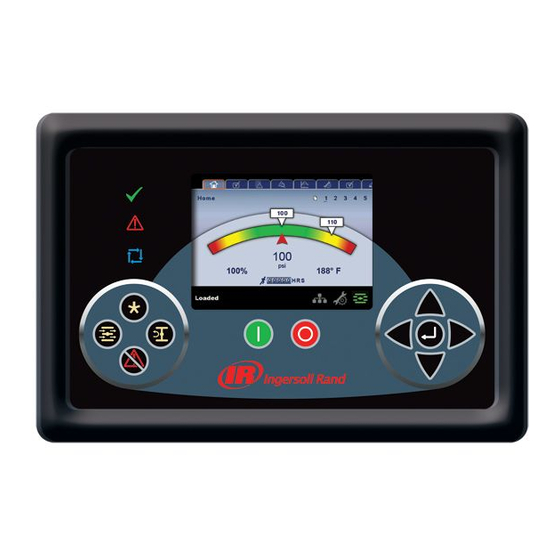
(i.e.: an air or oil filter needs to be changed). Unloaded Compressor is in the unloaded state. Compressor is in the loaded state. Loaded • SYSTEM OVERVIEW This is the factory default display after powering up the Xe-145M Dashboard Icons system. 80448905 Rev A... -
Page 9: Counters
RECIPROCATING COMPRESSORS Load Pressure - indicated in the white box and by the Starts - Indicates the number of times a start is attempted on white arrow, which is always left of center on the gauge. The the compressor. compressor will load when package discharge pressure falls Date &... -
Page 10: Operator Settings Folder
RECIPROCATING COMPRESSORS Package Discharge Temperature - The temperature of the Range (in degF): 150 - 500 air as delivered to the plant. Compressors Present: Two Stage Atmospheric, Three Stage 1st Stage Discharge Temperature - The temperature of the Atmospheric air as it leaves the first stage of the compression module. High 3rd Stage Discharge Temperature Trip - Determines 2nd Stage Discharge Temperature- The temperature of the the trip point for the 3rd Stage Discharge Temperature... -
Page 11: Operator Options
RECIPROCATING COMPRESSORS • OPERATOR OPTIONS Compressors Present: Two Stage Atmospheric, Three Stage Atmospheric, Two Stage Booster High 2nd Stage Discharge Pressure Trip - Determines the trip point for the 2nd Stage Discharge Pressure reading Range (in psi): 100 - 400 Compressors Present: Three Stage Atmospheric Low Frame Oil Presure Trip - Determines the trip point for the Frame Oil Pressure reading... -
Page 12: Calibrate Sensors
RECIPROCATING COMPRESSORS • CALIBRATE SENSORS • Power On • Power Off • Press the Start Key • Press the Stop Key • Press the Load Key • Press the Unload Key • Starting the compressor remotely • Stopping the compressor remotely •... -
Page 13: Over Pressure
RECIPROCATING COMPRESSORS before being recorded High Frame Oil Temperature On Screen Text: High Frame Oil Temperature High Suction Pressure Compressors Present: ALL On Screen Text: High Suction Pressure Will occur if the compressor has been running for at least Compressors Present: ESV Booster, Two Stage Booster, Two Start Time + 10 seconds (Star/Delta) or for 15 seconds (Other Airend Booster starter types) and the Frame Oil temperature reading is... - Page 14 RECIPROCATING COMPRESSORS High 1st Cylinder Discharge Temperature High Package Discharge Temperature On Screen Text: TBD On Screen Text: TBD Compressors Present: Two Airend Booster Compressors Present: ALL Will occur if the compressor has been running for at least Start Will occur if the compressor has been running for at least Time + 10 seconds (Star/Delta) for 15 seconds (Other starter Start Time + 10 seconds (Star/Delta) or for 15 seconds (Other types) and the 1st Cylinder Discharge Temperature reading...
-
Page 15: Sensor Failure
RECIPROCATING COMPRESSORS • Sensor Failure Will occur if the compressor is running and the high vibration switch opens for at least three seconds On-Screen Text: 3AVPT Failure High Package Discharge Pressure Compressors Present: ESV Atmospheric, Two Stage On-Screen Text: High Pkg Discharge Press Atmospheric, Three Stage Atmospheric. - Page 16 RECIPROCATING COMPRESSORS starter types) and the high package inlet temperature switch starter types) and the 3rd Stage Inlet temperature is greater opens for at least three seconds than or equal to the high 3rd stage inlet temperature setpoint High 1st Stage Discharge Temperature High 3rd Stage Discharge Temperature On Screen text: High 1st Stg DischT On Screen text: High 3rd Stg DischT...
-
Page 17: Sensor Failure
RECIPROCATING COMPRESSORS starter types) and the water inlet pressure is less than or equal condensate level switch opens for at least three seconds. to the low water inlet pressure setpoint. Note that this trip is High Aftercooler Condensate Level ignored if a closed loop water system is selected. On Screen text: High Aftercooler Condensate High Water Inlet Pressure Compressors Present: ALL... -
Page 18: Start Inhibit List
RECIPROCATING COMPRESSORS • Start Inhibit List TRIP HISTORY High 1st Stage Discharge Temperature • PAGES 1 TO A MAX OF 3 On Screen text: High 1st Stg DischT Compressors Present: ALL Will occur if the compressor is in a Ready to Start state and the 1st stage discharge temperature is greater than or equal to 97% of the high 1st stage discharge temperature setpoint High 1st Cylinder Discharge Temperature... -
Page 19: Graphing Selections
RECIPROCATING COMPRESSORS • PAGE 2 – MAINTENANCE STATUS X-Axis (Read Only - The time duration is selectable from page six. The sample rate varies, based on the selected duration. The graph plots a minimum of 255 readings • PAGE 6 – GRAPHING SELECTIONS This page displays the time until the unit should be serviced. -
Page 20: Units Of Measure Settings
RECIPROCATING COMPRESSORS • PAGE 4 – TIME & DATE SETTINGS Language (< >) is selectable from the following 30 selections: English (default) Finish Latvian Slovak Bulgarian French Lithuanian Slovenian Chinese, simplified German Maltese Spanish Croatian Greek Norwegian Swedish Czech Hungarian Polish Thai Danish... -
Page 21: Serial Port Address Settings
RECIPROCATING COMPRESSORS Subnet Mask Actual – Current reading/setting for the subnet mask NOTICE MAC Address – This is the unique hardware MAC address for THE START, STOP, LOAD, UNLOAD, RESET, AND the controller. This can not be changed. ACKNOWLEDGE KEYS ON THE X -145M REMAIN Enable DHCP –... -
Page 22: Status Folder
RECIPROCATING COMPRESSORS • PAGES 1 AND 2 – ANALOG INPUTS Integral Sequencing – Enabling Integral Sequencing selects this compressor to be the leader of the integral sequencing system. It is important that only one compressor in the sequence be selected as the lead compressor Unload Pressure –... -
Page 23: Compressor Data
RECIPROCATING COMPRESSORS • PAGES 4 THRU 5 – DIGITAL INPUTS • 2nd Stage Inlet Pressure - The pressure of the air at the intake of the 2nd stage of the compression module • 2nd Stage Discharge Temperature - The temperature of the air at the discharge of the 2nd stage of the compression module •... -
Page 24: Factory Settings Folder
RECIPROCATING COMPRESSORS • Condensate Solenoid of atmospheric and booster machines depending on standard equipment. Selections are ESV Atmospheric, Two Stage • Load Solenoids Atmospheric, Three Stage Atmospheric, ESV Booster, Two • Stopped in Auto-Restart Stage Booster, and Two Airend Booster •... -
Page 25: Commissioning Procedures
WEB ACCESS Ingersoll Rand Xe-90M/ X -145M web pages are a visualization application which offers a window using a web browser on your PC. The web pages allows the user to monitor air system at a glance or take a more detailed look into system operation, equipment status and setup through an intuitive web-page based user interface. -
Page 26: Connecting To A Pc
WEB ACCESS CONNECTING TO A PC In order to configure your computer to communicate point-to-point with the Xe-90M/ X -145M controller, you must first set the IP address range of your computer to the default IP address range of the controller. To do this, please follow the instructions listed below to configure the computer IP address. - Page 27 WEB ACCESS 2. Right click on the “Local Area Connection” and select “Properties”. 3. Scroll down the connection list to find the “Internet Protocol (TCP/IP)”. Select the “Internet Protocol (TCP/IP)” and click on “Properties”. 80448905 Rev A...
- Page 28 WEB ACCESS 4. Click on the “Alternative Configuration” tab. 5. Click on “User Configured” Button. 80448905 Rev A...
- Page 29 WEB ACCESS 6. Enter IP address for the computer (192.168.2.221), Enter the Subnet mask for the computer (255.255.255.0) and leave all other field boxes blank. 7. Click on “OK” button when it is complete. 80448905 Rev A...
-
Page 30: Ethernet Configuration
WEB ACCESS 8. Connect an Ethernet cable to your computer and to the controller. Within a minute, the computer will make a connection to the controller. Once connected, you will be able to log into and configure the controller. ETHERNET WIRES Wiring the network is accomplished by connecting the user computer to the controller using Category 5 (or better) cables. -
Page 31: Login Process
WEB ACCESS LOGIN PROCESS The server is accessed either by host name or by IP. Accessing by name requires that a router be in the network. During the installation and commissioning process a network address was assigned to the CONTROLLER by your IT department. This address may be a static IP (e.g. - Page 32 WEB ACCESS The login screen requires the user to enter their username, password and select the language for the web pages. This login screen will authenticate the user against the type of account. After log in the user can view/modify the data as per the available access to the user account.
-
Page 33: Default Accounts
WEB ACCESS DEFAULT ACCOUNTS The web page software comes with default administrator account. The system administrator can assign users one of three levels of access (view only, user and administrator) which will determine which functions will be available. For example, only users with administrator access will be able to create a new user account and view or modify the configuration overview parameters. -
Page 34: Navigation
WEB ACCESS NAVIGATION Each of the main segments is represented by a tab on the top of web pages. Clicking on the tab will bring you to the screen for that particular segment. TAB NAVIGATION The components of the tab navigation are as follows: Clicking this tab will bring the user to the HOME page. -
Page 35: Dashboard Icons
WEB ACCESS DASHBOARD ICONS “Dashboard Icons” are intended to be a quick at-a-glance view of system status. These icons are always visible regardless of the folder/page selected. The following table lists standard dashboard icons and their definition. Note that the color of these icons changes based on the state set by the application while running. -
Page 36: Home Page
WEB ACCESS HOME PAGE The “HOME” tab shows information about the compressor operating parameters, total power consumption, running hours, loaded hours, number of starts, etc Click on the pressure set point value in the white box, to change the “Pressure Set Point” value. Enter the new pressure set point value and click on “Confirm”... -
Page 37: Event Log Utility
WEB ACCESS EVENT LOG UTILITY The “EVENT LOG” tab shows the event log from the controller. This tab contains the event log details for the system events, warnings and trips that have occurred and provides first-out indication. It also provides controls for filtering the list of events as shown. - Page 38 WEB ACCESS The “Event Type” dropdown allows the user to filter the list of events by event type. The user can select the type of event from the list by clicking the dropdown control. The events recorded and placed into one of three categories: Warnings, Trips/ Shutdowns, and System Events.
-
Page 39: Performance Log Utility
WEB ACCESS PERFORMANCE LOG UTILITY The “PERFORMANCE LOG” tab shows the performance details and system data for the compressor including Average system pressure, hour meters, number of trips and warnings. The Performance log report provides a summary of the compressed air system’s performance for the selected time period. - Page 40 WEB ACCESS The “PERFORMANCE LOG” provides two dropdown controls that allow the user to select sampling of reporting and reporting settings. The user can change the frequency of reporting and monitoring interval by clicking on the dropdown controls. The time period of the performance report is selected based on the “Frequency of Reporting”. Click on the dropdown control and select the “Frequency of Reporting”...
-
Page 41: Graphing Utility
WEB ACCESS Whenever the user changes the “Frequency of reporting” and/or “Monitoring Interval”, a “Submit” button will appear on the screen. Click on “Submit” button to save the changes. GRAPHING UTILITY Click on “GRAPHING” tab to view the data in a graphical format for the selected analog input variable and time duration. The GRAPHING UTILITY allows the user to plot a graph on hour, day or week basis. - Page 42 WEB ACCESS When “Weeks” has been selected, the X axis will be scaled such that the span on graph represents duration of 1 week. The drop down menu allows the user to choose a variable to view data on the graph. Click on the dropdown menu and select the variable to monitor on the graph.
- Page 43 WEB ACCESS By moving the mouse over graph will display the determined value at the position of cursor with the date and time. Due to performance requirements the data on the real time chart cannot be interacted with directly so this allows the user to determine the approximate value of any data point.
-
Page 44: Inspection Log Utility
WEB ACCESS INSPECTION LOG UTILITY The “INSPECTION LOG” tab is intended to record machine data over a fixed period of time and a fixed rate. Inspection log contains the controller logged data for the variables at the time of download. The controls section of the “INSPECTION LOG” shows the user name currently set to receive inspection logs via email, as per the specified time interval and time of the day for instantaneous data. - Page 45 WEB ACCESS Click on the “Submit” button to save the changes into the report settings. The user will receive the INSPECTION LOG as per the selected time interval and time of the day. If the interval is “Daily” and time of day is “09:00” then the web page application will send inspection logs via email, everyday at 9:00 AM.
-
Page 46: Compressor Information
WEB ACCESS COMPRESSOR INFORMATION The “COMPRESSOR INFORMATION” tab contains the compressor name, compressor model number, compressor serial number, rated capacity, rated pressure, rated voltage, running current, starting current, power requirement, motor service factor, measuring units and Email (SMTP) settings. COMPRESSOR IDENTIFICATION The “Host Name”... -
Page 47: Email (Smtp) Settings
WEB ACCESS EMAIL (SMTP) SETTINGS If email notifications are to be used, the SMTP server settings must be obtained from IT and entered in this location. Enter the “SMTP Server” & “SMTP Account” and then click on “Submit” button to save the SMTP settings. User account with access level “Admin”... -
Page 48: Compressor Details
WEB ACCESS COMPRESSOR DETAILS Enter the rated capacity, rated pressure, rated voltage, running current, starting current, nominal power in kW and main motor service factor as per the data available in the compressor datasheet. Click on the “Submit” button to save the compressor details. UNIT TYPE Click on the dropdown control and select the measurement unit type for the compressor parameters. -
Page 49: Account Management
WEB ACCESS ACCOUNT MANAGEMENT The administrator can create any number of users desired and assign each user one of three levels of access, as well as assigning email notifications to various events that may occur. ADD ACCOUNT The “ACCOUNT” tab shows the list of accounts that currently exist which are listed by user name and access rights. Clicking on an account will highlight that account in blue color. - Page 50 WEB ACCESS To generate a new user account; enter the unique username, password and select the user access rights. Click on “Add Account” button will add the new user account into the list of user accounts. Only a user with “ADMIN” rights will be able to make a new account or remove the existing accounts.
- Page 51 WEB ACCESS MODIFY THE ACCESS LEVEL User account with access level “ADMIN” can also change the access level of existing user accounts. To change the access level or password of an existing user account, select the user account from the list and click the Change PW/AL button. Click on the dropdown control and choose the new access level for selected user account.
- Page 52 WEB ACCESS User account with access level “Admin” can only have an access to make a new account or modify the access level of these accounts. User account with access level “User” and “VIEW” can’t have an access to make a new account or modify the user accounts.
-
Page 53: Modbus Connection And Control
MODBUS CONNECTION AND CONTROL CONNECTION TO THE MODBUS NETWORK The Xe-145M controllers are designed to interface to any Modbus master capable device using Belden 9841 or equiv- alent RS-485 cable. In order to connect to the network, the cable must be connected to port COM2 on the controller as... -
Page 54: Modbus Table
MODBUS TABLE REGISTER VARIABLE READ/ RANGE NOTES (40XXX) WRITE Status/Control See FIGURE 1 Oil Pressure Water In Pressure Water Out Pressure Package Discharge Pressure 1st Stage Discharge Pressure 2nd Stage Discharge Pressure 3 Stage Units Only Suction Pressure Booster Units Only Inlet Vacuum Air Filter Press Drop Option Oil Temperature... - Page 55 MODBUS TABLE REGISTER VARIABLE READ/ RANGE NOTES (40XXX) WRITE Starter Time (seconds) 10 – 30 Auto Start/Stop (AS/S) Time (minutes) 2 – 20 Condensate Time (seconds) 3 – 60 Condensate Interval (seconds) 60 – 300 Auto Start Delay Time (seconds) 0 –...
- Page 56 MODBUS TABLE Bit 0: Host/Local (R/W) Bit 6: Alarm (R) 0 = Local 0 = No Alarms 1 = Host 1 = Alarms Bit 1: Run/Stop (R/W) Bit 7: Warning (R) 0 = Stop 0 = No Warnings 1 = Run 1 = Warnings Bit 2: Load/Unload (R/W) Bit 8: Constant Speed Mode (R)
- Page 57 MODBUS TABLE Register 94: Pressure - Modbus Register 95: Temperature - Modbus 0 = psi 0 = Degrees F 1 = kPa 1 = Degrees C 2 = bar 3 = kg/cm2 Register 098: Recip Type Register 104: Regulation 0 = ESV 0 = 2 Step 1 = ESV Booster 1 = 3 Step...
- Page 58 MODBUS TABLE Code Description Code Description Sensor Failure 1APT Low Suction Pressure Sensor Failure 2APT High Suction Pressure Sensor Failure 3APT Air Filter Pressure Drop Sensor Failure 4OPT High Discharge Pressure by Host Sensor Failure 5WPT Motor Not Synchronized Sensor Failure 6WPT Invalid Calibration Sensor Failure 7APT Closed Loop Water System...
- Page 61 .com © 2014 Ingersoll-Rand...
Need help?
Do you have a question about the Xe-145M and is the answer not in the manual?
Questions and answers
Controller cant be reset
To reset the Ingersoll-Rand Xe-145M controller, press the Reset command key on the membrane interface. If resetting an alarm in factory settings, add the factory passcode.
This answer is automatically generated
@Mr. Anderson Initiated reset on controller but no response
my display screen is running Dianostic how do i get the display to go back to normal
To reset the display screen on an Ingersoll-Rand Xe-145M from diagnostic mode and return to normal operation, you must acknowledge any trip condition by pressing the reset button. Once the trip is acknowledged, the compressor can start, and the display will return to normal operation.
This answer is automatically generated