Table of Contents
Advertisement
Quick Links
¨
¨
PRECISION INSTRUMENTS FOR TEST AND MEASUREMENT
1864-1644
Positive Polarity
Megohmmeter
User and Service Manual
Copyright © 2022 IET Labs, Inc.
Visit www.ietlabs.com for manual revision updates
1864-1644 im/May 2022
www.ietlabs.com
IET LABS, INC.
Email: info@ietlabs.com
TEL: (516) 334-5959 • FAX: (516) 334-5988
Advertisement
Table of Contents

Related Manuals for IET Labs 1864-1644


Summary of Contents for IET Labs 1864-1644
- Page 1 ¨ PRECISION INSTRUMENTS FOR TEST AND MEASUREMENT 1864-1644 Positive Polarity Megohmmeter User and Service Manual Copyright © 2022 IET Labs, Inc. Visit www.ietlabs.com for manual revision updates 1864-1644 im/May 2022 www.ietlabs.com IET LABS, INC. Email: info@ietlabs.com TEL: (516) 334-5959 • FAX: (516) 334-5988...
- Page 2 ¨ ¨ PRECISION INSTRUMENTS FOR TEST AND MEASUREMENT www.ietlabs.com IET LABS, INC. Email: info@ietlabs.com TEL: (516) 334-5959 • FAX: (516) 334-5988...
-
Page 3: Warranty
WARRANTY We warrant that this product is free from defects in material and workmanship and, when properly used, will perform in accordance with applicable IET specifi cations. If within one year after original shipment, it is found not to meet this standard, it will be repaired or, at the option of IET, replaced at no charge when returned to IET. -
Page 4: Safety Symbols
Safety Symbols General defi nitions of safety symbols used on the instrument or in manuals are listed below. Caution symbol: the product is marked with this symbol when it is necessary for the user to refer to the instruction manual. Hazardous voltage symbol: the product is marked with this symbol when high voltage maybe present on the product and an electrical shock hazard can exist. -
Page 5: Table Of Contents
1864-1644 Positive Polarity Megohmmeter Contents Condensed Operating Instructions ............iv Specifi cations .....................v 1864-1644 Specifi cations ....................v Chapter 1: INTRODUCTION ...............1 1.1 Description ....................... 1 1.2 Opening and Tilting the Cabinet ................1 1.3 Controls, Connectors and Indicators ................ 1 1.4 Symbols........................ - Page 6 1864-1644 Positive Polarity Megohmmeter Chapter 4: APPLICATIONS ................15 4.1 Insulation Testing ..................... 15 4.2 Test Sample Resistivity Measurements ..............16 4.3.1 General ......................16 4.3.2 Charging Time Constant ................16 4.3.3 Measurement Time Constant ................. 17 4.3.4 Discharge Time ....................17 4.3.5 Large Capacitors, Very High Resistance ............
- Page 7 1864-1644 Positive Polarity Megohmmeter CONTENTS, FIGURES, AND TABLES...
-
Page 8: Safety Summary
DEGREE 2 as defi ned in IEC61010-1. Voltages of up to 1090 Vdc maybe present at measurement terminals of the 1864-1644 Megohmmeter If an instrument is marked CAT I (IEC Measurement Category I), or it is not marked with a... - Page 9 To avoid the danger of introducing additional hazards, do not install substitute parts or perform unauthorized modifi cations to the instrument. Return the instrument to an IET Labs for service and repair to ensure that safety features are maintained in operational condition.
-
Page 10: Specifi Cations
1864-1644 Positive Polarity Megohmmeter Specifi cations 1864-1644 Specifi cations Fuse: Resistance Accuracy (min reading 0.5): For 100 to 125 V operation: Range 1-5: ±2 (meter reading+1)% Fuse: T 0.25A, 250V (PN 0034.3111) Where meter reading is the actual number indicated at the scale; e.g. for a reading of For 200 to 250 V operation: 900 kΩ... - Page 11 SWITCH POWER-OFF SWITCH TEST-VOLTAGE SWITCHES 1864-1644 Front-panel Controls, Connectors and Indicators 4. Connect the unknown to the UNKNOWN termi- 1. Determine which ground link connection is to be nals. used (paragraph 3.1.1 ). 5. Measure the unknown with either the search (para- 2.
- Page 12 1864-1644 Positive Polarity Megohmmeter This page intentionally left blank. viii CONTENTS, FIGURES, AND TABLES...
-
Page 13: Chapter 1: Introduction
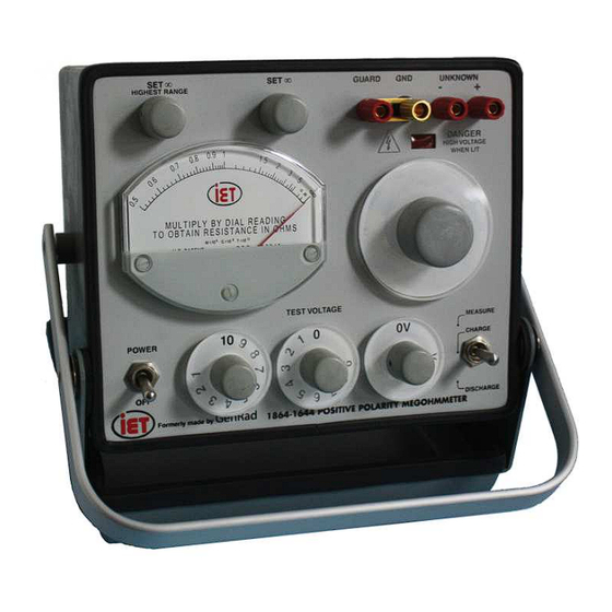
INTRODUCTION WARNING High voltage is applied to the measurement terminals of 1864-1644 Megohmmeters at all times, except when the function switch is set to DISCHARGE. While the current is limited to a value that is not dangerous under most conditions, the energy stored in a capacitor connected to the terminals may be LETHAL. - Page 14 1864-1644 Positive Polarity Megohmmeter Figure 1-1. Type 1864-1644 Front-panel Controls, Connectors and Indicators INTRODUCTION...
- Page 15 1864-1644 Positive Polarity Megohmmeter Figure 1.1 Name Type Function Reference POWER 2-position toggle Turn power on and off. switch Indicates the value to be 4-in. meter with Meter multiplies by the multiplier plastic cover switch. Adjusts high end of meter SET ¥...
- Page 16 1864-1644 Positive Polarity Megohmmeter Figure 1-2. Type 1864-1644 rear-panel controls and connectors Table 1.2. Figure 1-2 Name Type Function Reference Power Input IEC Standard Power input Power input and circuit protection receptacle. Output Phone jack Provides a dc voltage output for recorder...
-
Page 17: Controls, Connectors And Indicators
1864-1644 Positive Polarity Megohmmeter 1.3 Controls, Connectors and 1.4 Symbols Indicators These instruments indicate the resistance of the un- known in multiples of ohms. The relationship between Figure 1-1 shows the front-panel controls, connec- ohms (Ω), kilohms (kΩ), megohms (MΩ), gigaohms tors and indicators of the 1864. - Page 18 1864-1644 Positive Polarity Megohmmeter This page intentionally left blank. INTRODUCTION...
-
Page 19: Chapter 2: Installation
2.1 Initial Inspection 2.3 Repackaging for Shipment IET instruments receive a careful mechanical and If the instrument is to be returned to IET Labs, contact electrical inspection before shipment. Upon receipt, the Service Department at the number or address, verify that the contents are intact and as ordered. -
Page 20: Storage
Hz power line. The 1864-1644 Megohmmeters is for indoor use only. B e f o r e c o n n e c t i n g t h e 3 - w i r e I E C power cord to the line, set the slide switch on the There are no special requirements for ventilation. -
Page 21: Safety Considerations
MEAS/CHARGE/DISCHARGE toggle switch. See Chapter 6 for more information on calibration and service. 10. The 1864-1644 should be located on a bench or other surface so as not to make the equipment dif- 2.12 Cautions Regarding Use of Instrument fi... -
Page 22: Instrument Return
Service Lab and will serve as a reference number for the time your unit is at IET Labs. It will be necessary to include a Purchase Order Num-... -
Page 23: Chapter 3: Operation
3.1.2 Test Voltage Selection The TEST VOLTAGE switch(es) should be set to the desired measurement voltage. The 1864-1644 Megohmmeter has a selection of 10 to 109 Vdc in 1-V steps or 100 to 1090 Vdc in 10-V steps. On the... -
Page 24: Measurement Procedure
Every precaution has been taken in the design of depending on whether or not the correct resistance- 1864-1644 Megohmmeter to reduce the possibility multiplier range is known. If the range is not known, of shock. However, high voltage must be present at the search procedure (paragraph 3.2.2) should be... -
Page 25: Output Jack
1864-1644 Positive Polarity Megohmmeter 3.3 Output Jack The OUTPUT jack (J105) on the rear panel makes accessible a dc voltage that is directly proportional to the reciprocal of the meter reading, that is, the highest value is at the 0.5 scale reading and the lowest value is at ∞. - Page 26 1864-1644 Positive Polarity Megohmmeter This page intentionally left blank. OPERATION...
-
Page 27: Chapter 4: Applications
A com- plete charge-current-vs-time plot will provide more useful information. The 1864-1644 Megohmmeters can be used for ei- ther true leakage measurements or for measurements at 1-or 10-minute intervals following the operating procedure described in Section 3. -
Page 28: Test Sample Resistivity Measurements
1864-1644 Positive Polarity Megohmmeter WARNING Capacitors being measured may be charged and may contain lethal energy. Always set the function switch to DISCHARGE before connecting or disconnecting the capacitor under test. 4.3.2 Charging Time Constant The time constant for charging a capacitor in the CHARGE position is determined by the value of Figure 4-1. -
Page 29: Measurement Time Constant
1864-1644 Positive Polarity Megohmmeter Dielectric absorption (dipole and interfacial polariza- 4.3.4 Discharge Time tion) is present in many capacitors and insulators, With the function switch set at DISCHARGE, the especially those with a laminated structure. When UNKNOWN terminals are connected through 470 W... -
Page 30: Resistance Measurements
1864-1644 Positive Polarity Megohmmeter 1. Dielectric absorbtion. (paragraph 4.3.2). This is 4.5 Measurement of Voltage Coeffi cient the main cause of erroneous readings. Besides the diffi culty in deciding what charging period should be The 1864 Megohmmeter may be used to measure used, the previous history of the capacitor will greatly voltage coeffi... -
Page 31: Guarded 3-Terminal Measurements
1864-1644 Positive Polarity Megohmmeter 4.6 Guarded 3-Terminal Measurements 4.8 Measurements Under Humid Conditions In many cases it is necessary to measure the resistance between two points in the presence of resistance from The 1864 Megohmmeter has been designed to operate each of these points to a third point. - Page 32 1864-1644 Positive Polarity Megohmmeter This page intentionally left blank. APPLICATIONS...
-
Page 33: Chapter 5: Theory
1864-1644 Positive Polarity Megohmmeter Chapter 5 THEORY 5.2.2 Type 1863 Megohmmeter (Figure 7.6) 5.1 General The voltage supply section (RECT.) of the 1863 The 1864 Megohmmeter basically consists of a regu- consists of fi ve diff erent circuits, three dc and two ac. - Page 34 1864-1644 Positive Polarity Megohmmeter Figure 5-1 Megohmmeter block diagram A unity-gain FET-input amplifi er (+1) follows the 5.2.3 Type 1864 Megohmmeter (Figure 7.9) standard resistors in the circuit confi guration. R210 The circuit of the 1864 Megohmmeter is basically and C203 comprise a low-pass fi lter input to FET the same as that of the 1863 (paragraph 5.2.2).
-
Page 35: Chapter 6: Service And Maintenance
1864-1644 Positive Polarity Megohmmeter Chapter 6 SERVICE AND MAINTENANCE WARNING Dangerous voltages are present inside this case. When troubleshooting, a ground strap should be connected between GUARD and GROUND on panel to keep the subpanel (Guard) at ground potential. Refer all servic- ing to qualifi... - Page 36 1864-1644 Positive Polarity Megohmmeter 16. Set the POWER/OFF switch to OFF and disconnect the decade resistor. 17. Connect the Digital Multimeter between the GUARD and -UNKNOWN terminals with two single banana plug patch cords. 18. Connect the two ground terminals together with a third patch cord (Figure 6.1).
-
Page 37: Cabinet Removal
1864-1644 Positive Polarity Megohmmeter 6.3 Cabinet Removal To remove the instrument from the cabinet, remove the two screws on the rear of the instrument cabinet and pull the instrument out of the cabinet. Warning Be careful when troubleshooting the instrument when it is out of its cabinet and connected to the power line. -
Page 38: Troubleshooting
1864-1644 Positive Polarity Megohmmeter 6.4 Troubleshooting 6.4.1 General The following information is designed to assist in troubleshooting the 1863 and 1864 Megohmmeters. An understanding of the theory involved in these instruments (Section 5) makes the instrument easy to analyze because the problem can usually be located quickly in either the voltage regulator or in the meter circuit. -
Page 39: Coarse ∞ Adjustment
1864-1644 Positive Polarity Megohmmeter If all the voltages are out of tolerance in the same 6.5.4 Range-Resistor Accuracy direction, they can be set within the tolerance by adjusting R140 located on etched-circuit board P/N The range resistors can be checked by performing 1864-2701 (common to both the 1863 and 1864 Meg- procedure steps in of section 6.2. -
Page 40: Knob Removal
1864-1644 Positive Polarity Megohmmeter 6.6 Knob Removal If it should be necessary to remove the knob on a front-panel control, either to replace one that has been damaged or to replace the associated control, proceed as follows: 1. 1. Grasp the knob fi rmly with the fi ngers,... -
Page 41: Knob Installation
1864-1644 Positive Polarity Megohmmeter As supplied by IET, the meter should return to zero 6.7 Knob Installation reading within 30 seconds, immediately following the placement of a static charge, as by rubbing the To install a knob assembly on the control shaft: outside surface. - Page 42 1864-1644 Positive Polarity Megohmmeter This page intentionally left blank. SERVICE AND MAINTENANCE...
-
Page 43: Chapter 7: Parts Lists And Diagrams
1864-1644 Positive Polarity Megohmmeter Chapter 7 PARTS LISTS AND DIAGRAMS PARTS LIST AND DIAGRAMS... - Page 44 1864-1644 Positive Polarity Megohmmeter PARTS LIST AND DIAGRAMS...
-
Page 45: Replaceable Parts List
1864-1644 Positive Polarity Megohmmeter Figure 7-1. Replaceable mechanical parts on the 1864-1644 Replaceable parts list Model Ref IET Pt No Description 7910-1300-02 Power switch 5730-1412-01 Meter assembly 5520-5220-AS Knob assembly for 1863/64 potentiometers 3770-2 Red binding post 01-1008-1-0310 Gold binding post... - Page 46 1864-1644 Positive Polarity Megohmmeter Figure 7-2. Regulator and amplifi er circuits etched-board assembly Figure 7-3. Type 1864 rectifi er circuit etched-board assembly (P/N 1864-2720) PARTS LIST AND DIAGRAMS...
- Page 47 1864-1644 Positive Polarity Megohmmeter PARTS LIST AND DIAGRAMS...
- Page 48 1864-1644 Positive Polarity Megohmmeter PARTS LIST AND DIAGRAMS...
- Page 49 1864-1644 Positive Polarity Megohmmeter Figure 7-6. Complete cabinet assembly PARTS LIST AND DIAGRAMS...
- Page 50 1864-1644 Positive Polarity Megohmmeter PARTS LIST AND DIAGRAMS...
Need help?
Do you have a question about the 1864-1644 and is the answer not in the manual?
Questions and answers