Table of Contents
Advertisement
Quick Links
¨
¨
PRECISION INSTRUMENTS FOR TEST AND MEASUREMENT
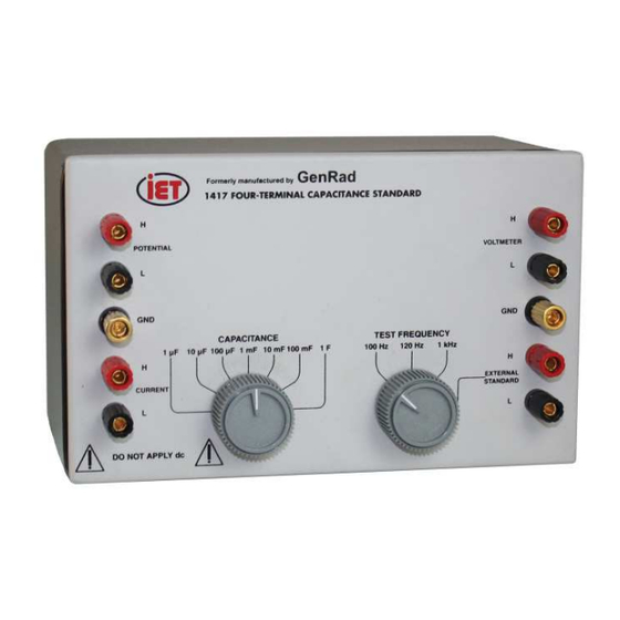
1417 FOUR-TERMINAL
CAPACITANCE STANDARD
User and Service Manual
Copyright © 2024 IET Labs, Inc.
Visit www.ietlabs.com for manual revision updates
IET/GenRad 1417-im August 2024
www.ietlabs.com
IET LABS, INC.
Email: info@ietlabs.com
TEL: (516) 334-5959 • FAX: (516) 334-5988
Advertisement
Table of Contents

Subscribe to Our Youtube Channel
Related Manuals for IET Labs 1417


Summary of Contents for IET Labs 1417
- Page 1 ¨ ¨ PRECISION INSTRUMENTS FOR TEST AND MEASUREMENT 1417 FOUR-TERMINAL CAPACITANCE STANDARD User and Service Manual Copyright © 2024 IET Labs, Inc. Visit www.ietlabs.com for manual revision updates IET/GenRad 1417-im August 2024 www.ietlabs.com IET LABS, INC. Email: info@ietlabs.com TEL: (516) 334-5959 • FAX: (516) 334-5988...
- Page 2 ¨ ¨ PRECISION INSTRUMENTS FOR TEST AND MEASUREMENT www.ietlabs.com IET LABS, INC. Email: info@ietlabs.com TEL: (516) 334-5959 • FAX: (516) 334-5988...
- Page 3 WARRANTY We warrant that this product is free from defects in material and workmanship and, when properly used, will perform in accordance with applicable IET specifi cations. If within one year after original shipment, it is found not to meet this standard, it will be repaired or, at the option of IET, replaced at no charge when returned to IET.
- Page 4 WARNING OBSERVE ALL SAFETY RULES WHEN WORKING WITH HIGH VOLTAGES OR LINE VOLTAGES. Dangerous voltages may be present inside this instrument. Do not open the case Refer servicing to qualifi ed personnel HIGH VOLTAGES MAY BE PRESENT AT THE TERMINALS OF THIS INSTRUMENT WHENEVER HAZARDOUS VOLTAGES (>...
-
Page 5: Table Of Contents
2.2.2 Terminal Impedances ............................8 2.2.3 Connecting Leads ..............................8 2.2.4 Mutual Inductance In Leads ..........................8 2.3 Accuracy ..................................9 2.3.1 Accuracy of the 1417 ............................9 2.3.2 Required Accuracy ..............................9 2.3.3 Direct-Reading Measurements ........................10 2.4 Calibration Corrections for Better Accuracy ....................10 2.4.1 The 1 μF Calibration ............................ - Page 6 Figure 2-2. Changes in capacitance vs voltage at VOLTMETER terminals..........10 Figure 2-1. Methods of connection to binding-post terminals ..............10 Figure 2-3. Connection diagram for 1417 calibration checks................ 13 Figure 2-4. Typical capacitance with frequency. Note corrections are made at 100 Hz and 120 Hz. 1 4 Figure 4-1.
- Page 7 Tables Table 2-1 ................................... 14 Table 3-1 ................................... 15 Table 3-2 ................................... 16 Table 3-3 ................................... 16 Table 3-4 ................................... 16 Table 3-5 ................................... 17 Table 3-6 ................................... 17 Table 3-7 ................................... 17 Table 3-8 ................................... 17 Table 3-9 ................................... 17 Table 3-10 ..................................
- Page 8 Weight: 2.7 kg (6 lb.) net, 5 kg (11 lb.) shipping. Dissipation Factor: 0.01 at 100 Hz, 120 Hz and 1 kHz. For D accuracy, see table. Capacitance Change versus Voltage Capacitance Change versus Frequency Order Number 1417-9700 Four-Terminal Capacitance Standard...
-
Page 9: Chapter 1
Most instruments that measure high capacitance do accuracy of the 1 mF calibration, with the latter being so at 100 Hz, 120 Hz or 1 kHz; the 1417 is compen- more important as long as the ratio remains constant. sated to have good direct-reading accuracy at these frequencies. -
Page 10: Controls And Connections
1.3 Controls and Connections The pairs of terminals on the left are those that should be connected to the measuring instrument. They are labeled POTENTIAL AND CURRENT, common There are 2 panel knobs driving rotary switches. The nomenclature for a 4-terminal standard. Generally, CAPACITANCE switch selects the capacitance value these are connected to bridge terminals with similar as indicated when the internal standard is used. -
Page 11: Chapter 2
OPERATION 2.2.2 Terminal Impedances 2.1 General The 1417 has impedance in series with each of its terminals as shown in Figure 4-4 and Table 4-2. The manner in which the 1417 should be used depends These have no eff ect on a perfect 4-terminal measure- on many factors: the accuracy required, the test fre- ment. -
Page 12: Accuracy
Mutual inductance between the current circuit and At 1 kHz, the level eff ect is negligible (less than the potential circuit occurs in the 1417, the con- 0.004%), but (see paragraph 2.2.4) mutual induc- necting leads, and inside the measuring instrument. -
Page 13: Direct-Reading Measurements
± 5°C and 1-kHz values of the 1417 so long as it is below 20 V. 4.At 100 Hz or 120 Hz, the level at the VOLTMETER terminals is less than 5 V (or the voltage at the CURRENT terminals is less than 0.25%... -
Page 14: Approximate Level Corrections
1417. These Figure 2-2, determine the approxi- bridges normally apply a low voltage to the unknown. -
Page 15: The Capacitance Vs Level Corrections
1417 used, to measure the the eff ect of errors in the main bridge adjustment. voltage at the VOLTMETER terminals at each setting of the 1417 during use, and to apply the previously Since the 1656 is only 0.1 % accurate and because determined correction. -
Page 16: Use Of An External Standard
Figure 2-3. Connection diagram for 1417 calibration checks. and the instrument. If the voltage at, these terminals The larger the external capacitance, the less (percent) exceeds about 27 V rms, these diodes will clip and error will occur. This error can be quite large at low fre-... -
Page 17: Applicaton Of Other Frequencies
2.8 Two-Terminal Measurements or increasing the value to 1 μF, by adding pad- The lower values of the 1417 may be used as a 2-ter- ding capacitors at the VOLTMETER terminals. minal standard at low frequencies. The D is increased... -
Page 18: Section 3
1417 is usually adequate, but a single caused by hum pickup. This error can and should calibration of the 1417 at 1 μF (see para 2.4.1) is be removed by making two measurements with the nevertheless suggested as a precaution. The volt-... -
Page 19: Use With 1657 Digibridge
1 mF at 1 kHz. Note that the maximum reading is 999.99 mF at 1 kHz and 99.999 mF at 120 Hz. It would be preferable to use an external standard with the 1417, of say 0.9 μF to check these range extremes. -
Page 20: With 2230 Systems
Table 3-5 Table 3-6 Table 3-7 Table 3-8 Table 3-9... -
Page 21: Use With Iet Digibridges
Digibridge accuracy is as electrolytic capacitor). If dc current fl ows there will good as the 1417 ratio accuracy so that a true accuracy be an error in the capacitance measurement so use verifi cation is not possible but nevertheless, tests with of this blocking capacitor is always recommended. -
Page 22: Zeroing And Minimizing Mutual Inductance
2.2.4), even though the position of the 1 F so that there is no point in checking accuracy terminals on the 1417 minimizes this eff ect. It is above that value. The actual accuracy will be well also suggested that the free ends of the test cable... - Page 23 These instruments have such tight tolerances that particularly if several measurements are averaged, the changes in the 1417 values with signal level are so that the specifi ed averaged, so that the specifi ed important. This leads to a somewhat paradoxical...
- Page 24 Table 3-17...
-
Page 25: Chapter 4
4-terminal device (see Paragraph 2.8). 4.2 Basic Circuit The basic circuit of the GR 1417 is shown in Figure The first two factors are the reciprocals of the 4-1. C is the internal 1µF and the two autotransform- open-circuit divider ratios α... -
Page 26: Terminal Impedances
CT is the 4-terminal transfer capacitance. This value has an error that depends on frequency Usually the coupling internal to the 1417 is sub- squared, as shown. It also depends on signal level stantially less than the coupling in the external because of the nonlinearity of inductance L. -
Page 27: Dissipation Factor
50 Hz. 4.5 Dissipation Factor The dissipation factor of the 1417 is intentionally which can be written as: set to be 0.01 at 100 Hz, 120 Hz and 1 kHz (at the appropriate switch setting). - Page 28 Table 4-2...
-
Page 29: Chapter 5
Chapter 5 SERVICE AND MAINTENANCE 5.1 IET Field Service 5.3 Calibration Procedure Our warranty attests the quality of materials and If the low-level value of the 1 µF CAPACITANCE workmanship in our products. When difficulties setting for any TEST FREQUENCY position is do occur, our service engineers will assist in any found to be outside limits at 23°... -
Page 30: Determination Of Other Parameters
1000 to a.Set the 1417 TEST FREQUENCY switch to EX- 1 ratio to this precision. One should note that the 1417 TERNAL STANDARD. b.With the oscillator at low level, connect it to the 1417 could have applications as a precision divider. -
Page 31: Knob Installation
5.5.3 Knob Installation NOTE To install a knob assembly on the control shaft: Make sure that the end of the shaft does not protrude through the bushing or the a.Place the black Nylon thrust washer over the control knob won’t set properly. shaft, if appropriate. - Page 32 Table 5.1 Replacement List Model Ref IET Pt No Description 01-1033-8-0312 Binding Post, Red 01-1033-8-0310 Binding Post, Black 01-1008-1-0310 Binding Post, Gold 5500-5421-01 Knob, IET Style Not Shown 5331-3100 Gasket...
-
Page 33: Figure 5-2. Test Frequency Switch (S2) Details Showing Padding Capacitors
Figure 5-2. TEST FREQUENCY Switch (S2) details showing padding capacitors.
Need help?
Do you have a question about the 1417 and is the answer not in the manual?
Questions and answers