Table of Contents
Advertisement
Quick Links
♦
♦
PrEcision insTrumEnTs For TEsT And mEAsurEmEnT
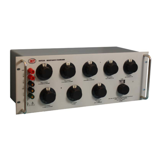
RS-925D
Resistance Standard
User and Service Manual
Copyright © 2014 IET Labs, Inc.
Visit www.ietlabs.com for manual revision updates
RS-925D Sept. 2014
IET LABS, INC.
www.ietlabs.com
Email: info@ietlabs.com
TEL: (516) 334-5959 • (800) 899-8438 • FAX: (516) 334-5988
Advertisement
Table of Contents

Subscribe to Our Youtube Channel
Related Manuals for IET Labs RS-925D


Summary of Contents for IET Labs RS-925D
- Page 1 ♦ ♦ PrEcision insTrumEnTs For TEsT And mEAsurEmEnT RS-925D Resistance Standard User and Service Manual Copyright © 2014 IET Labs, Inc. Visit www.ietlabs.com for manual revision updates RS-925D Sept. 2014 IET LABS, INC. www.ietlabs.com Email: info@ietlabs.com TEL: (516) 334-5959 • (800) 899-8438 • FAX: (516) 334-5988...
- Page 2 ♦ PrEcision insTrumEnTs For TEsT And mEAsurEmEnT IET Model RS-925D This rs-925d is the iET Labs version of the original esi rs 925d decade resistance standard. The iET unit is updated and features a number of significant performance improvements. Among these are: -sealed resistors for better stability and imperviousness to moisture.
-
Page 5: Table Of Contents
Contents Chapter 1 Introduction ................1 1.1 Introduction ......................1 Chapter 2 Specifications ................2 Specifications ........................ 2 Chapter 3 Installation ................4 3.1 Initial Inspection ....................4 3.2 Installation ......................4 3.3 Repackaging for Shipment ..................4 3.4 Storage ........................4 Chapter 4 Operation ..................5 4.1 Initial Inspection and Setup .................. - Page 6 Figures and Tables Figure 1-1: RS-925D Decade Resistance Substituter .........1 Figure 2-1: Typical Operating Guide Affixed to Unit ........3 Figure 4-1: Rheostat Dial ................6 Figure 4-2: Rheostat Schematic ..............6 Figure 4-3: Kelvin Bridge Connections ............7 Table 5-1: Trimming Potentiometers ............11 Figure 5-1: Typical Trimmer Board ...............11...
-
Page 7: Chapter 1 Introduction
With a resolution as low as 20 ΩΩ and a maximum to develop the best stability characteristics. Actual available resistance of over 12.1 MΩ, the RS-925D- experience has shown them to exhibit a storage sta- 11-0.001-RH may be employed for exacting precision... -
Page 8: Chapter 2 Specifications
RS-925D Chapter 2 SpECIfICaTIOnS For convenience to the user, the pertinent specifications are given in a typical OPERATING GUIDE, like the one shown in Figure 2.1, affixed to the case of the instrument. SpECIfICaTIOnS Total Temperature Power Resistance Stability current... -
Page 9: Figure 2-1: Typical Operating Guide Affixed To Unit
RS-925D Specifications... -
Page 10: Chapter 3 Installation
3.1 Initial Inspection 3.3 Repackaging for Shipment IET instruments receive a careful mechanical and If the instrument is to be returned to IET Labs, contact electrical inspection before shipment. Upon receipt, the Service Department at the number or address, verify that the contents are intact and as ordered. -
Page 11: Chapter 4 Operation
CURRENT HI, CURRENT LO, SENSE HI, and The highest quality low emf components are used in SENSE LO provide two current and two potential the RS-925D Series. In particular, the terminals are terminals, respectively, for 4-terminal measurement. made of gold plated tellurium copper, which exhibits 2-terminal measurements may be made by shorting low emf and low resistance. -
Page 12: Dial Setting
In order to eliminate contact resistance and thermal 1 0 0 0 0. 0 0 0 emf, the RS-925D integrates the rheostat as shown in 1 0 0 0. 0 0 0 Figure 4-2. This way, the wiper is in the low potential 1 0 0. -
Page 13: Environmental Conditions
For maximum protection and accuracy, limit power To perform this “breaking in,” simply rotate each input to RS-925D to 1Watt. This may be accom- plished by placing a resistor in series with the bridge switch seven to ten times in each direction. -
Page 14: Chapter 5 Maintenance
5.2 preventive Maintenance If the RS-925D is employed as a stand alone device, the following should be observed: Keep the unit in a clean environment. This will help •... -
Page 15: General Considerations
RS-925D unit, and/or the 5.3.4 Calibration procedure uncertainty of the measurement instrumenta- tion has to be considered in the calibration To calibrate the RS-925D unit, proceed as follows: Test Uncertainty Ratio (TUR). 1. Set up the calibration equipment in the re- •... -
Page 16: Adjustments
If the minimum 10 mΩ needs to be adjusted, consult 4. Rotate all knobs approximately 10 times. IET Labs. For other resistors, adjust the resistors Breaking in the switches helps elimi- from lowest to highest. The order of decades does nate any residual contact corrosion not matter. -
Page 17: Figure 5-1: Typical Trimmer Board
RS-925D Potentiometer Designation Potentiometer Designation Switch Position All decades but 1 k Ω 1 kΩ decade T10 (1 M steps only) Table 5-1: Trimming Potentiometers Trim Pots Figure 5-1: Typical Trimmer Board Maintenance... -
Page 18: Replaceable Parts List
10 kΩ/step Decade Switch Assembly Not Shown HARS-4000-LX-100k 100 kΩ/step Decade Switch Assembly Not Shown HARS-4000-LX-1M 1 MΩ/step Decade Switch Assembly Not Shown HARS-4000-LX-10M 10 MΩ/step Decade Switch Assembly Table 5-2: Replaceable Parts List Figure 5-2: RS-925D Replaceable Parts Maintenance...
Need help?
Do you have a question about the RS-925D and is the answer not in the manual?
Questions and answers