Table of Contents
Advertisement
Quick Links
♦
♦
PRECISION INSTRUMENTS FOR TEST AND MEASUREMENT
1920
Precision LCR Meter
User and Service Manual
Copyright © 2012 IET Labs, Inc.
Visit www.ietlabs.com for manual revision updates
1920 im/February 2012
IET LABS, INC.
www.ietlabs.com
534 Main Street, Westbury, NY 11590
TEL: (516) 334-5959 • (800) 899-8438 • FAX: (516) 334-5988
Advertisement
Table of Contents

Related Manuals for IET Labs 1920


Summary of Contents for IET Labs 1920
-
Page 1: Introduction - Section
♦ PRECISION INSTRUMENTS FOR TEST AND MEASUREMENT 1920 Precision LCR Meter User and Service Manual Copyright © 2012 IET Labs, Inc. Visit www.ietlabs.com for manual revision updates 1920 im/February 2012 IET LABS, INC. www.ietlabs.com 534 Main Street, Westbury, NY 11590... - Page 2 ♦ ♦ PRECISION INSTRUMENTS FOR TEST AND MEASUREMENT IET LABS, INC. www.ietlabs.com 534 Main Street, Westbury, NY 11590 TEL: (516) 334-5959 • (800) 899-8438 • FAX: (516) 334-5988...
-
Page 3: Table Of Contents
Contents Warranty ......................7 Specifications ......................9 Accessories ......................11 Safety Precautions ....................15 Condensed Operating ....................17 Installation and Power Up Selecting Test Conditions Zeroing Connection to Device Under Test Initiating Tests Introduction - Section 1 Unpacking/Inspection ..................31 Product Overview ..................31 Front Panel Description .................32 Rear Panel Description ..................34 Installation ......................35 1.5.1 Dimensions ..................35... - Page 4 Contents (continued) 2.3.13 Load Correction .................60 2.3.14 Primary Load Correction ..............61 2.3.15 Secondary Load Correction ..............61 Program/Sequence (Test S1-S9) ..............62 Utility Functions ....................64 2.5.1 Perform Calibration ................65 2.5.2 Keypad Lockout .................69 2.5.3 Display Type ..................72 2.5.4 Numeric Format .................73 2.5.5 Trigger Source ..................74 2.5.6 Source Impedance ................74 2.5.7 RS-232 Baud Rate ................75 2.5.8 IEEE488 Address ................75...
- Page 5 Contents (continued) Theory - Section 4 Introduction ....................95 4.1.1 Description of 1920 Precision LCR Meter ........95 4.1.2 Block Diagram ...................97 Principle Functions ..................99 4.2.1 Fundamental Measurement ..............99 4.2.2 Sine Wave and Sampling Pulse Generator ........100 4.2.3 Digitization ..................100 Service & Calibration - Section 5 General ......................103...
- Page 6 Page 6 of 109...
-
Page 7: Warranty
WARRANTY We warrant that this product is free from defects in material and workmanship and, when properly used, will perform in accordance with applicable IET specifi cations. If within one year after original shipment, it is found not to meet this standard, it will be repaired or, at the option of IET, replaced at no charge when returned to IET. - Page 8 WARNING OBSERVE ALL SAFETY RULES WHEN WORKING WITH HIGH VOLTAGES OR LINE VOLTAGES. Dangerous voltages may be present inside this instrument. Do not open the case Refer servicing to qualifi ed personnel HIGH VOLTAGES MAY BE PRESENT AT THE TERMINALS OF THIS INSTRUMENT WHENEVER HAZARDOUS VOLTAGES (>...
-
Page 9: Specifications
Specifications Measure Parameters: Parameter Range Basic Accuracy Medium High ±0.5% ±-0.25% ±0.1% Ls, Lp 0.001nH to 99.999kH ±0.5% ±0.25% ±0.1% Cs, Cp 0.01pF to 9.9999F ±0.005 ±0.0025 ±0.001 .00001 to 99.999 ±0.005 ±0.0025 ±0.001 .00000 to 9999.9 ±0.5% ±0.25% ±0.1% Y, Gp, Bp 10nS to 9999.9S 0.00001mΩ... - Page 10 Specifications (continued) Results Format: Engineering Numeric Deviation from Nominal of Primary Parameter % Deviation from Nominal of Primary Parameter No Display (for maximum throughput) Interfaces: IEEE-488, RS-232, Handler I/O Measurement Delay: 0 to 100s, programmable in 10 ms steps Averaging: 1 to 1000, programmable Mechanical: Bench Mount (optional rack mount flanges available, 2000-16)
-
Page 11: Accessories
Accessories Accessories Included Item Quantity QuadTech P/N AC Power Cord 4200-0300 Power Line Fuse (installed in instrument) 520049 Instruction Manual 150566 Calibration Certificate Accessories/Options Available Item Quantity QuadTech P/N Axial/Radial Component Test Fixture 1700-01 Axial/Radial Remote Test Fixture 1700-02 4 BNC Connectors to 2 Kelvin Clip Lead Set 1700-03 4 BNC Connectors to 4 Banana Plugs, w/alligator clips 1 1700-04... - Page 12 Accessories (Continued) QuadTech 1700-02 TEST FIXTURE HIGH Axial Lead Adaptors Short Rotated 90 degrees as shown Figure A-2: 1700-02 Axial/Radial Remote Test Fixture Black Black Black Black Figure A-3: 1700-03 BNC (4) Connectors to 2 Kelvin Clip Lead Set Black Black Black Black...
- Page 13 Accessories (Continued) Black Black Figure A-5: 1700-05 BNC (4) Connectors to 2 Kelvin Clip Lead Set Rd/Wh Rd/Wh Bk/Wh Bk/Wh Figure A-6: 7000-01 BNC (4) to BNC (4) Cable Set, 1 meter 7000-02 BNC (4) to BNC (4) Cable Set, 2 meters Figure A-7: 7000-07 Low Voltage Chip Component Test Fixture Page 13 of 109...
- Page 14 The 2000-16 Rack Mount Flanges (quantity 2, left and right) are used as dress panels to adapt the 1920 to the standard 482.6 mm (19 inch) rack width. THESE FLANGES SHOULD NOT BE USED AS SOLE MOUNTING SUPPORT OF THE 1920 in rack mount applications.
-
Page 15: Safety Precautions
Safety Precautions The 1920 Precision LCR Meter can provide an output voltage to 1.0V AC and 2.0V DC to the device under test (DUT). Although the 1920 unit is designed with full attention to operator safety, serious hazards could occur if the instrument is used improperly and these safety instructions are not followed. - Page 16 Safety Symbols The product is marked with the following safety symbols. Product will be marked with this symbol (ISO#3864) when it is necessary for the user to refer to the instruction manual in order to prevent injury or equipment damage. Product marked with this symbol (IEC417) indicates presence of direct current.
-
Page 17: Condensed Operating
Condensed Operating Instructions Start-Up The 1920 Precision LCR Meter can be operated from a power source between 90 and 250 VAC at a power line frequency of 50 to 60 Hz. The unit is shipped with a 2.5A fuse in place for 90 to 250 V operation. - Page 18 Condensed Operating Instructions Programming Test Conditions Press the UP or DOWN arrow to select test # (location where test conditions are stored). Test # (1 - 30) 1.000kHz Sequence Test # (S1 - S10) 1.000V No Bias Auto High Refer to paragraph 2.4 Press PROGRAM to enter programming mode Press [PROGRAM] at any 1 Prim Param...
- Page 19 Condensed Operating Instructions Amplitude Press theRIGHT arrow to selectamplitude of voltage Right Amplitude Program 20.00 mV Press theUP or DOWN arrow to changeamplitude value 20.00mV - 1.0000V Amplitude Program 1.0000 V in 5mV steps Bias Voltage Press theRIGHT arrow to selectbias voltage Not shown if Primary Right...
- Page 20 Condensed Operating Instructions Delay Press the RIGHT arrow to select delay time Right Delay Program 0.00 ms Press the UP or DOWN arrow to change delay time value 0msec to 100.00sec Delay Program 100.00 sec in 10msec steps Averaging Press the RIGHT arrow to select number to average Right No.
- Page 21 Condensed Operating Instructions Binning (Primary Parameter) Press the RIGHT arrow to select type Not shown if Primary Right Bin Type Program Parameter is set to Automatic Press the UP or DOWN arrow to change type Absolute, Percent Deviation Bin Type Program Absolute or Off...
- Page 22 Condensed Operating Instructions Secondary Nominal Press the RIGHT arrow to select secondary nominal value Not shown if Primary Right Sec Nominal Program Parameter is set to Automatic Press the UP or DOWN arrow to change secondary nominal value Off, or range of values and Sec Nominal Program units that depend on...
- Page 23 Condensed Operating Instructions Load Correction Press the RIGHT arrow to select load correction Not shown if Primary LoadCorrect (START = GET) Right parameter is set to Automatic Press the UP or DOWN arrow to change load correction value LoadCorrect (START = GET) Off, On Measure Press [START] to measure Load Correction based on primary and secondary nominals...
- Page 24 Condensed Operating Instructions Programming Tester Utility Functions Tester functions are accessed through the UTILITY mode. Cal with 1M Cable Press [UTILITY] at any time to [UTILITY] Cal Due: 1/10/2001 exit programming mode. Perform Calibration/Zeroing Press the RIGHT arrow to skip Open/Short and go to Keypad Lockout with indicated cable length Indicates due date of next Cal with 1M Cable Right...
- Page 25 Condensed Operating Instructions Remove Open. Connect SHORT standard. Press START to continue. Connect Test Leads in SHORT configuration to 1930 SHORT Kelvin Leads Clipped Together Press the [START] to initiate short calibration measurement [START] Short Correction factor C: 1 9: F1 I5 Short correction Calibration Complete Press START to continue...
- Page 26 Condensed Operating Instructions RS-232 Baud Rate Press the RIGHT arrow to select RS-232 baud rate Right RS232 Baud Rate Util 9600 Press the UP or DOWN arrow to change RS-232 baud rate value 9600, 19200, 9600Auto, RS232 Baud Rate Util 19200 19200Auto, or Disabled IEEE-488 Address...
- Page 27 Condensed Operating Instructions Leveling Press the RIGHT arrow to select leveling Right Leveling Util Press the UP or DOWN arrow to change leveling value Leveling Util Off or On Cable Compensation Press the RIGHT arrow to select cable compensation Cable Comp. Util Right Front Panel Connect...
- Page 28 Condensed Operating Instructions Median Press the RIGHT arrow to select median Median Util Right Single Meas. Press the UP or DOWN arrow to change median type Single Measurement or Median Util Median of 3 Median of 3 measurements Distortion Press the RIGHT arrow to select distortion Distortion Util...
-
Page 29: Connection To Device Under Test
Condensed Operating Instructions Connection to Device Under Test (DUT) Figure COI-1 illustrates the connection of the 1920 LCR Meter to a device under test using the 4-BNC to 2-Kelvin Clip lead set (QT P/N 1700-03). 1920 Precision LCR Meter QuadTech... - Page 30 Condensed Operating Instructions Make sure the device under test (DUT) is connected to the instrument as previously described. To initiate a test on the device press the START key. The LCD display shows the measured results depending on the operator programming of Display Type and Numeric Format.
-
Page 31: Unpacking/Inspection
% deviation from a programmed nominal value. The 1920’s AC test signal is programmable from 20 mV to 1 V and DC bias voltage programmable from 0 to 2 V. -
Page 32: Front Panel Description
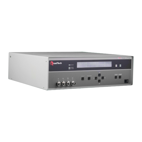
Front Panel Description Figure 1-1 illustrates the controls and indicators on the front panel of the 1920 Precision LCR Meter. Table 1-1 identifies them with description and function. 1920 Precision LCR Meter QuadTech QuadTech Bias On Model 1920 V1.4 Remote... - Page 33 Table 1-1 (continued) Front Panel Controls and Indicators BNC female connector Current high connection to DUT BNC female connector Potential high connection to DUT BNC female connector Potential low connection to DUT BNC female connector Current low connection to DUT LOCKOUT Green LED Indicator Indicates front panel keypad lockout is enabled...
-
Page 34: Rear Panel Description
Input/Output connections for handler interface IEEE-488 24 pin connector Input/Output connections for IEEE-488 interface Note User cable specifications for use with CE Mark 1920 RS-232 Shielded cable required Remote I/O Cable must be double shielded (inner braid and outer foil) -
Page 35: Installation
Installation 1.5.1 Dimensions The 1920 Precision LCR Meter is supplied in a bench configuration, i.e. in a cabinet with resilient feet for placement on a table or bench. Figure 1.3 illustrates the 1920 instrument dimensions. The unit can be configured for rack mount applications using the 2000-16 optional Rack Mount Flanges. - Page 36 Procedure for changing fuse WARNING MAKE SURE THE UNIT HAS BEEN DISCONNECTED FROM ITS AC POWER SOURCE FOR AT LEAST FIVE MINUTES BEFORE PROCEEDING. NO USER SERVICEABLE PARTS INSIDE TO PREVENT ELECTRICAL SHOCK DO NOT OPEN COVERS REFER TO QUALIFIED PERSON CAUTION: FOR CONTINUED PROTECTION AGAINST FIRE HAZARD REPLACE ONLY...
-
Page 37: Safety Inspection
Do not expose the instrument to direct sunlight, extreme temperature or humidity variations, or corrosive chemicals. When the 1920 is used in a rack installation (using the QuadTech 2000-16 Rack Mount Flanges) make sure the unit is secured using rack cabinet mounting rails, and not secured solely by these front panel flanges. -
Page 39: Terms And Conventions
Section 2: Operation/Programming Terms and Conventions Table 2-1 Measurement Unit Prefixes Multiple Scientific Engineering Symbol 10 15 1000000000000000 Peta 10 12 1000000000000 Tera 10 9 1000000000 Giga 10 6 1000000 Mega 10 3 1000 Kilo 10 -3 .001 milli 10 -6 .000001 micro 10 -9... - Page 40 Capacitance: The ratio of charge on either plate of a capacitor to the Potential difference (voltage) across the plates. When a voltage is applied, current flows immediately at a high rate then exponentially decays toward zero as the charge builds up. If an AC voltage is applied, an AC current appears to flow continuously because the polarity of the voltage is reversed at the frequency of the applied voltage.
-
Page 41: Power Up
Power Up Once the 1920 is powered up it is ready for immediate testing if test conditions have been previously stored in one of the internal memory locations (user tests 1 thru 30). Any of these test conditions and other instrument settings can be changed by easy-to-use menu functions. -
Page 42: Primary Parameter
Any combination of two AC parameters, or two DC parameters, can be measured and displayed simultaneously on the 1920, one referred to as the Primary (displayed first) and the other the Secondary (see paragraph 2.3.2). The instrument can be set for a primary parameter selection of Auto, a feature which enables any passive component to be measured without knowing what type of component it is. - Page 43 The following selections are possible and discussed in more detail below. Ls - Inductance in henries P – Phase Angle in degrees Lp - Inductance in henries |ESR|-Equivalent series resistance in ohms Rs - Resistance in ohms Gp - Conductance in siemens Rp - Resistance in ohms Xs - Reactance in ohms Cs - Capacitance in farads...
- Page 44 Impedance is the parameter used to characterize electronic components, materials and circuits. Impedance |Z| is defined as the opposition a device or circuit offers to the flow of ac current at a particular frequency and generally represented as a complex quantity consisting of a real part (resistance, R) and imaginary part (reactance, jX).
-
Page 45: Secondary Parameter
Quality factor (Q) is used as a measure of a reactance's purity (how close it is to being a pure reactance, i.e. no resistance) and defined as the ratio of the energy stored in a device to the energy dissipated by the device. Q is dimensionless and is expressed as Q = X/R = B/G. -
Page 46: Frequency
DUT is never more than the programmed voltage, and depends on the DUT impedance and source resistance of the 1920, which can be 5Ω, 25Ω 50Ω or 100Ω. Refer to Utility functions, paragraph 2.5.6 for information on the source impedance. The instrument source resistance must be taken into consideration especially when measuring low values of impedance (low inductance or high capacitance). -
Page 47: Bias Voltage
DC voltage is applied to the device under test. When selected for AC Coupled a large value blocking capacitor is switched in to protect the 1920 measurement circuit from DC voltages. This mode of operation is intended primarily for battery impedance measurement applications. -
Page 48: Range Select
1 Bias Voltage Program Up or Down arrow key to change bias voltage 1 Bias Voltage Program 1.00 mV 1 mV to 2 V 1 Bias Voltage Program 2.0000 V Right arrow key to program next parameter PROGRAM key to exit Program Mode and return to Ready mode. - Page 49 1 Range Select Program Up or Down arrow key Auto to change range 1 Range Select Program Hold 1 Range Select Program Lock 200 mA, any F 1.0V 27 ranges (45 for DC) 1 Range Select Program Lock 2.6 µ A F<=10K 62 mV Right arrow key to program next parameter...
- Page 50 V (AC voltage across the device), secondary parameter to I (current through the device), and initiate a test. The voltage and current measured can be compared to the previous table where the appropriate range is determined with the measured values falling below the maximums listed. 1920 Source Resistance PROGRAM MEASURE...
-
Page 51: Accuracy
Remote I/O interface. The instrument will make a more precise measurement when programmed for High, but there is a tradeoff in measurement speed as indicated below. Table 2-3: 1920 Accuracy Accuracy Setting Measure Time... - Page 52 The 1920 has three basic levels of accuracy Basic For AC High 0.10% Medium 0.25% Low & Low No Display 0.5% The actual accuracy at a given test condition is defined by the following formula: ...
-
Page 53: Delay
For Inductors if Q < 10 Accuracy Accuracy 1 Accuracy Accuracy Note: Due to the large time constants involved in measurements of high value inductors, additional inaccuracies may result. This will be indicated by reduced display resolution. Temperature: Error doubles for every 10 ° C from 23 ° C 2.3.8 Delay This function allows the user to program a delay time between 0 and 100s in 10ms steps. -
Page 54: To Average
2.3.9 No. to Average This function allows the user to program the number of measurements to average between 1 and 999. If the entered value is 1, averaging is disabled and the display is updated with each individual measurement. If the entered average is 10 the instrument will make 10 measurements and then display the average value. -
Page 55: Primary Nominal
Refer to paragraph 2.5.3. 3) The nominal value (or actual known value) when implementing the load correction feature of the 1920. Refer to paragraph 2.3.13. This function allows the user to select a nominal value for the primary displayed parameter, selection of nominal value for the secondary parameter is discussed in paragraph 2.3.12. -
Page 56: Bin Type
A group of similar components can be measured and categorized according to operator programmed limits. For example, the 1920 can be used to sort a group of nominally- valued 100 kΩ resistors into assigned bins of 1%, 2%, 5%, etc., around a nominal value, or sorted by absolute limits which are independent of any nominal value. - Page 57 Fail Fail Bin 3 Bin 2 Bin 1 Bin 3 75.00 kΩ 85.00 kΩ 95.00 kΩ 105.00 kΩ 125.00 kΩ 1 Bin Type Program Up or Down arrow key to change bin type 1 Bin Type Program Pct. Deviation Right arrow key to 1 Bin 1 HiLim Program...
- Page 58 Right arrow key to 1 Bin 2 HiLim Program select bins 2 thru 10 Hi and Lo limits Up or Down arrow Bin 2 thru 10, Hi & Lo limits to change them PROGRAM key, at 1 Bin 10 LoLim Program any time, to return to Ready mode...
-
Page 59: Secondary Nominal
2.3.12 Secondary Nominal (not shown if Secondary Parameter is set to “No Secondary parameter”) This function allows the user to select a nominal value for the secondary displayed parameter and to program high and low limits around this nominal. These limits are selected in absolute value or % deviation about this nominal (determined by bin type selection, refer to paragraph 2.3.11). -
Page 60: Load Correction
Measurement accuracy is 0.25 x (normal accuracy) with Load Correction implemented and compared to user supplied standard and for the same measurement conditions (test voltage, test frequency, and 1920 measurement range). This increased accuracy applies in a range of: DUT's with impedance (Z) between 3Ω and 800kΩ, with programmed voltage from 100mV to 1V Load correction can be set to Off or On. -
Page 61: Primary Load Correction
2.3.14 Primary Load Correction The value shown is the measured load correction for the primary parameter, which can be further altered by the operator as shown below. Primary Load Correction = Load Correction Measured minus the Primary Nominal value) For example, if the load correction measured is 148.000nH (para 2.3.13) and the primary nominal is 140.000nH, the primary load correction shown here would be –8.0000nH. -
Page 62: Program/Sequence (Test S1-S9)
Program/Sequence (Test S1-S9) Sequence tests (S1 through S9) are selected by pressing Up or Down arrow key when instrument status is in the Ready or power up mode. 1.0000 KHz 1.000V NoBias Auto High Sequence Test # Instrument Ready status 1 3 5 7 9 10 User tests # to be performed in... - Page 63 Sequence 1, Test 4 Right arrow key to select S1 : 4 Program test # 4 in the sequence Test : 8 S1 : 4 Program Up or Down arrow key Tests 1 – 30, skip or Test : 9 to change test # for test 4 none Sequence 1, Test 5...
-
Page 64: Utility Functions
Utility Functions The Utility functions allow the user to set instrument functions that affect all tests. When the UTILITY key is pressed the first function, Cal, and other functions (as list below) are accessed by pressing the Right arrow key. BOLD settings are the default settings. Table 2-3: Programmable Parameters For Utility Functions Programmable Settings... -
Page 65: Perform Calibration
Open/short data is deleted by going in and out of PROGRAM mode or programming any parameter of the current single test via remote. The operator is prompted by the 1920 display when performing the cal procedures. - Page 66 The example below performs a quick open/short, other routines are similar with user prompting displayed on the instrument display. Cal with 1 M Cable Right arrow key to skip Indicates due date Cal Due: 1/10/2001 Open/short and go to Keypad next annual calibration Lockout Quick Short/Cal...
- Page 67 C: 1 9: F1 Press START to initiate Open correction Indicates # of record in Indicates index of frequency table which controls cal (0 for DC, 1-14 for ac) C: 1 9: F1 Indicates progression of Open correction the cal routine, counts up Index of current range Index of voltage range NOTE...
- Page 68 Press START to initiate C: 1 9: F1 (DC Short Correction) Short correction Connect SHORT standard. Press START to continue. C: 1 9: F1 Press START to initiate Short correction (AC Short Correction) Calibration Complete. Press START to continue. Press START, unit returns to 1.0000 KHz READY mode for testing 1.000V NoBias Auto High...
-
Page 69: Keypad Lockout
2.5.2 Keypad Lockout Selection of Off allows the operator to modify any stored test conditions and use all functions of the instrument, with no restrictions. When a password is entered for Lock Password only, the currently selected test conditions, along with the instrument START and STOP functions are active. - Page 70 Keypad Lockout Util Lock Cycle Tests Passwd Right arrow key to Keypad Lockout Util enter password 000000 Up or Down arrow Keypad Lockout Util key to change the first 800000 digit (0 thru 9) Right arrow key to Keypad Lockout Util move to next digit 800000...
- Page 71 To unlock Password Press Utility key Keypad Lockout Util Keypad Lockout Util On With Test Number Up or Down arrow key Keypad Lockout Util to unlock password Enter Password to Unlock Right arrow key to Keypad Lockout Util enter password 000000 Up or Down arrow...
-
Page 72: Display Type
2.5.3 Display Type Measured Parameters, Display is the measured values of both the primary and secondary, displayed with decimal point and units. Deviation from Nominal, Display is the difference in measured value above or below (-) a programmed nominal value for the primary and secondary parameters. Refer to paragraph 2.3.10, programming the primary nominal and paragraph 2.3.12, programming the secondary display. -
Page 73: Numeric Format
2.5.4 Numeric Format Allows selection from two different measurement results formats, Scientific or Engineering units. Scientific units are expressed as an exponent and engineering units are expressed in ohms for resistance, farads for capacitance, henries for inductance, etc. For example e 3 in scientific units can be expressed as kΩ in engineering units or e -3 in scientific units can be expressed as mΩ... -
Page 74: Trigger Source
UTILITY key to exit and return to Ready mode. 2.5.6 Source Impedance This function allows the operator to select the 1920’s output source impedance, selections available are 5, 25, 50, and 100Ω Ω Ω Ω . In general the measuring instrument’s source impedance will usually have a direct effect on the measured impedance of the device. -
Page 75: Baud Rate
2.5.7 RS-232 Baud Rate This function allows the operator to select the baud rate when communicating via the RS- 232 interface, selections possible include 9600, 19200, 9600 AutoReport, 19200 AutoReport or Disabled. The Auto Report options are used to log test results and error messages on a receive-only serial device, such as a serial printer. -
Page 76: Clear All Tests
2.5.9 Clear All Tests This selection allows the operator to clear all stored test setups in instrument memory (1 thru 30 for single tests or S1 thru S10 for sequential tests). After this operation, all tests are programmed to defaults coded by instrument software, which is generally as follows: Primary: Range: Automatic... -
Page 77: Cable Comp
No Cable, 1 M Cable or 2 M Cable. The 1920 is factory calibrated to compensate for the various lengths of test cables, choosing the correct cable length is important to assure accurate measurements. In addition to this, an open short circuit should be conducted any time the cable length is changed, refer to paragraph 2.5.1. -
Page 78: Median
2.5.13 Median This function allows the operator to choose single or median measurement mode. When median of 3 is selected three individual measurements are made, the lowest and highest values are discarded and the median value displayed. Median mode can improve instrument accuracy by: specified accuracy/divided by 3 ;... -
Page 79: Serial Number
2.5.15 Serial Number This function allows the operator to view the instrument serial number. This serial number can also be returned when the unit is under remote control but there is no command for changing this number. Serial Number 0104985 Right arrow key to program next Utility function... - Page 80 Operator Help messages (continued) DSP appears busy. Press STOP to clear DSP did not take enough samples Test is disabled program sequence test DSP reported invalid params; check setup Frequency and locked range incompatible Locked range invalid for AC; set to HOLD Primary nominal invalid Set to default Secondary nominal invalid;...
-
Page 81: General
Section 3: Interface General The 1920 Precision LCR Meter includes three interfaces standard with the unit, the Remote I/O , RS-232 and IEEE-488. Connection for these are located on the instrument’s rear panel and discussed in detail below. Remote I/O The 1920 comes standard with an automatic component remote I/O interface port available through a 37 pin DB type connector located on the rear panel of the instrument. - Page 82 Table 3-1 Remote I/O Interface Connections Signal Name Pin Number Function Outputs: Busy Measurement in process Bin 1 Primary Pass Secondary Pass if binning is enabled and all Primary bin limits are set to Off All steps in a Sequence test are Pass Bin 2 Primary Pass or...
-
Page 83: Interface
RS-232 Interface An RS232 serial port interface is available on the 1920 through a 9 pin DIN connector on the rear panel of the instrument. The RS232 standard defines electrical specifications for the transmission of bit serial information. The use of the RS232 port requires three lines, receive data, transmit data, and signal ground. -
Page 84: Ieee-488.2 Interface
IEEE-488.2 Interface 3.4.1 General An IEEE-488 interface is available standard on the 1920 through a connector (24 pin) on the rear panel. This interface can be used to connect to a system containing a number of instruments and a controller in which each meets IEEE Standard 488.2 (Standard Digital... -
Page 85: Ieee-488 Connections
3.4.2 IEEE-488 Connections Figure 3-3 IEEE-488 Interface Pin Configuration Table 3-3 IEEE-488 Interface Connections Signal Name Pin Number Function ___________________ Low state: "Data is Available" and valid on DI01 through DI08 NRFD 7 Low state: At least one listener on the bus is "Not ready for Data". -
Page 86: Ieee-488 & Rs-232 Commands
CONFigure or SYSTem commands that follow should only be used with the commands for which they were intended. The 1920 commands are interpreted as numeric values but for convenience in programming they are not entered as numeric but rather as a more understandable command. For example; when programming the primary parameter for Lp it would appear as “CONF: PPAR LP”, which is also equivalent to “CONF:... - Page 87 Table 3-4 (Continued) IEEE & RS-232 Commands Command Function Parameter(s) CONFigure: PPARameter Set primary parameter AUTO LS LP RS RP CS CP DF Q Z Y P ESR GP XS BP V I DCV DCR DCI SPARameter Set secondary parameter NONE LS LP RS RP CS CP DF Q Z Y P ESR GP XS BP V I...
- Page 88 Table 3-4 (Continued) IEEE & RS-232 Commands Command Function Parameter(s) SEQuence: TEST Set current step to test number nn NONE SKIP SYSTEM: LOCKout Lockout keypad from the remote OFF ON DISPlay Set display type DMEAS DDEV DPCT FRESult Format result type SCI ENG TRIGger Trigger type...
- Page 89 Table 3-4 (Continued) IEEE & RS-232 Commands Command Function Parameter(s) MEASure Triggers a measurement of the selected type. If sequence is enabled this command will trigger those type of measurements also. The result type is set by the display type parameter Triggers a measurement of the selected type, and automatically returns the answer after the measurement is complete.
- Page 90 Table 3-4 (Continued) IEEE & RS-232 Commands Command Function Parameter(s) If the secondary parameter is set to NONE, the format will be: n.nnnnEmmm<space>*<space> If the secondary parameters is set to anything other than NONE, the format will be: n.nnnnEmmm<space> n.nnnnEmmm <space> If the measurement is invalid for some reason (typically an A/D overrange, because normally the range will be locked to shorten the cycle time), the return format will be:...
- Page 91 This is a convenient way to see what the actual limits will be when setting up a test *IDN? Returns instrument identification "QuadTech, 1920,xx...xx, software version”. x denotes serial number up to 8 digits *ESR? Returns the read of the event status register.
-
Page 92: Formats
*The Status Byte Register is readable via the standard *STB? as defined in paragraph. 11.2.2.2 of the IEEE spec. The 1920 will also implement an SRE register to enable each bit of the Status Byte Register per paragraph 11.3.2 of the IEEE spec. This register shall be readable by a SRE? command and writeable by a SRE <#>... - Page 93 Standard Event Status Register Decimal Value Power Up Since Last Query None Command Error (Syntax) Execution Error (Over Range, etc.) None Query Error None Operation Complete This register is read by executing an “*ESR?” command per paragraph 11.5.1.2.2 (except no *). Note that this is a destructive read. Reading the register clears it. Each bit of the Event register must be enabled in order to cause the ESB bit of the Status Register to be set.
-
Page 95: Introduction
4.1.1 Description of 1920 Precision LCR Meter In the model 1920 Precision LCR Meter, the voltage across the device under test (DUT) is measured, and the current through the DUT is measured across a reference resistor Rs which carries substantially the same current. - Page 96 The detection and excitation circuitry is configured for each measurement by an embedded computer. For the excitation circuitry this includes frequency of excitation, DC bias current, and excitation level. Frequency is varied from 20Hz to 1MHz. Excitation level is between 20mV and 1V (open circuit). For the detection circuitry this includes the reference resistor, the gain in the current and voltage detectors, and analog filtering optimized for the frequency of excitation.
-
Page 97: Block Diagram
4.1.2 Block Diagram The block diagram, Figure 4-1, shows the embedded computer connected via a CPU bus (B) composed of address, control and data lines to the other major functional blocks of the circuit. The embedded computer includes the following types of memory: RAM for Program execution, FLASH for non-volatile program storage, EEROM for storage of calibration data, instrument configuration, and test setups. - Page 98 Bias Control Current Detector Analog to Power Digital Buffer CPU Bus (B) Converter Sine Wave and Sample Digital Sinal Pulse Processor Generator Embedded Computer Display and Remote Keyboard Interfaces Figure 4-1 1920 Instrument Block Diagram Page 98 of 109 Theory...
-
Page 99: Principle Functions
Principal Functions 4.2.1 Fundamental Measurement The fundamental measurement technique is illustrated as a simplified diagram in Figure 4-2. A sine wave generator drives current IH through the DUT and a standard resistor in series. Two differential amplifiers with controlled gains produce voltages Ex and Es. Simple algebra results in an expression for the complex impedance. -
Page 100: Sine Wave And Sampling Pulse Generator
The two samples are taken very nearly at the same time. Any delay of one channel relative to the other is calibrated out digitally during the calibration process. Figures 4-3, 4-4 and 4-5 further illustrate the signal flow and test points within the 1920 Precision LCR Meter. - Page 101 Voltage Current Figure 4-4 Detector Circuits Theory Page 101 of 109...
- Page 102 Figure 4-5 Digital Signal Processor Page 102 of 109 Theory...
-
Page 103: General
QuadTech. Calibration Calibration of the 1920 LCR Meter is completed at the factory and includes a NIST calibration certificate. Verification of instrument operation and accuracy is recommended on an annual basis. Accurate operation of the 1920 instrument is confirmed using the following verification procedure. - Page 104 Verification Data Sheet. If the calibrated values for the standards used do not have an uncertainty of 4 times better than the specified accuracy of the 1920 the uncertainty of the standard should be added to the specified accuracy of the 1920. For example: if the calibrated value of the 500mΩ...
- Page 105 See paragraph 2.5.1 for information on performing an open and short correction. Connect each standard listed in the Verification Data Sheet and select the test frequency on the 1920 as listed, see paragraph 2.3.3. Record the results in the Verification Data Sheet. Service & Calibration...
-
Page 106: 1920 Verification Data Sheet
5.3.2 1920 Verification Data Sheet R500M Freq Pri. Actual Sec. Actual Voltage Primary Meas. Sec. Meas. Pspec Sspec 1000 0.327% 0.0033 10000 0.327% 0.0033 100000 0.460% 0.0047 Freq Pri. Actual Sec. Actual Voltage Primary Meas. Sec. Meas. Pspec Sspec 1000 0.120%... - Page 107 L1000uH Freq Pri. Actual Sec. Actual Voltage Primary Meas. Sec. Meas. Pspec Sspec 1000 0.477% 0.2389 10000 0.161% 5.0163 100000 0.177% 55.2771 C50pF Freq Pri. Actual Sec. Actual Voltage Primary Meas. Sec. Meas. Pspec Sspec 1000 0.959% 0.0109 100000 0.352% 0.0084 1000000 1.889%...
- Page 108 C10nF Freq Pri. Actual Sec. Actual Voltage Primary Meas. Sec. Meas. Pspec Sspec 1000 0.120% 0.0014 100000 0.162% 0.0038 1000000 0.654% 0.0354 C20nF Freq Pri. Actual Sec. Actual Voltage Primary Meas. Sec. Meas. Pspec Sspec 1000 0.118% 0.0013 100000 0.162% 0.0038 1000000 0.689%...
-
Page 109: Diagnostics
Diagnostics 5.3.1 Start-up Diagnostics On start-up the unit displays step numbers during the initialization process. Should the display stop during this initialization the number displayed serves as a diagnostic tool. The numbers correspond to the following functions: (1) Verifies (initializes if necessary) cal data corresponding to No Cable (direction connection to the front panel.
Need help?
Do you have a question about the 1920 and is the answer not in the manual?
Questions and answers