Table of Contents
Advertisement
Quick Links
Advertisement
Table of Contents

Subscribe to Our Youtube Channel
Related Manuals for HydroQuip BALBOA BP100


Summary of Contents for HydroQuip BALBOA BP100
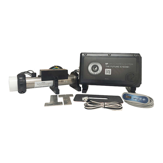
- Page 1 BP100 Installation/Operation Manual For the following models 50-BP1-200-40-K, 50-BP1-200-4R-K, 50-BP1-200-55-K, 50- BP1-200-5R-K, 50-BP1-500-40-K, 50-BP1-500-4R-K, 50-BP1- 500-55-K, 50-BP1-500-5R-K (Remote Heater System) (Fixed Heater System)
-
Page 3: Table Of Contents
Contents Important Safety Instructions......4-5 Electrical Installation...........6-9 Pump Cord Installation.........10 Spa-Side Installation..........11 WiFi Module Intallation Kit........12 Circuit Board Configurations........13 Wiring Diagrams...........14 Systems Setup Options........15 Programming with a TP500/TP500S....16 Programming with a TP600/TP400/TP200...17 DIP Switch Settings..........20 System Start-Up..........20-21 Operational Considerations........21 System Functions / Features......22-23 Plug Pin-Outs/Sensor Replacement.....24 TroubleShooting ..........25-26 Data Label/Warranty Info........27... -
Page 4: Important Safety Instructions
IMPORTANT SAFETY INSTRUCTIONS DANGER To reduce the risk of injury, do not permit children to use this product unless they are closely supervised at all times. WARNING - RISK OF CHILD DROWNING. Extreme caution must be exercised to prevent unauthorized access by children. To avoid accidents, ensure that children cannot use a spa or hot tub unless they are supervised at all times. - Page 5 IMPORTANT SAFETY INSTRUCTIONS Persons using medication should consult a physician before using a spa or hot tub since some medication may affect heart rate, blood pressure, and circulation. For Cord and Plug Connected Units Must be connected to a grounded, grounding type receptacle only. NEVER connect the spa to an extension cord.
-
Page 6: Electrical Installation
Electrical Installation A licensed electrician must accomplish the electrical installation in accordance with the National Electric Code(NEC) Article 680, and any local codes in effect at the time of installation. Refer to the System Data Label for equipment voltage and maximum amperage draws. The GFCI (Ground Fault Circuit Interrupter) is a mandatory electrical safety device required for all portable spas and hot tubs as specified in the National Electrical Code Article 680-42. -
Page 7: Electrical Connections
Electrical Installation ELECTRICAL CONNECTIONS OPTION 1 GFCI Installed in Main Service Panel 20-60AMP HARDWIRED MAIN BREAKER PANEL INLINE SPA DISCONNECT PORTABLE SPA LINE 1 LINE 2 REFER TO GFCI WIRING DETAIL ON PAGE 8 Option 1 shows the power from GFCI breaker installed into main service panel to a service disconnect within line-of- site of the spa. - Page 8 Electrical Installation If your system was configured to include a 120VAC power cord, ensure that the proper receptacle has been installed (a dedicated circuit is required). DO NOT under any circumstances modify a 20 Amp plug to fit into a 15 Amp receptacle or use an extension cord.
-
Page 9: Power Connection
Power Connection IMPORTANT: Always refer to the product data label (located on top of the control box) for specific electrical information. Use copper conductors only as required by the NEC. Ÿ Secure wires as defined by the NEC and in compliance with any local codes in effect Ÿ... - Page 10 Pump Cord Connections 2-SPEED PUMP CORD CONFIGURATION The following wiring configuration is for two-speed pump circuits. Black = Low Speed Red = High Speed System Pump White = Common Green = Ground SINGLE SPEED PUMP / ACCESSORY CORD CONFIGURATION The following wiring configuration is for single-speed pump circuits, circulation pumps, ozones, blowers and accessories.
-
Page 11: Spaside Control Installation
SPASIDE CONTROL INSTALLATION If required, you may have to cut out a hole in the spa shell to install spaside control. The mounting area must be above the maximum water level of the spa and in an area with good Ÿ... -
Page 12: Wifi Module Intallation Kit
WIFI MODULE INSTALLATION KIT (OPTIONAL) Your new system has the capability to connect with the internet using a wifi module. If Provided with your system, please make sure to install the module following these few steps: Step 1 - Insert wifi cable connector into an empty connection mark “Main” Topside may vary * If no main connections are available, you may use the “Y”... -
Page 13: Circuit Board Configurations
Circuit Board Configurations Component Plugs Area Area Component Voltage Configurations Component outputs are pre-configured for 240. If 120V output is required, please utilize the illustration below and the wiring diagram on page #14 to convert the required circuit. 120V 240V Voltage Selection Chart for 120V Conversion Component Volts... - Page 14 F3 0.1A SLO-BLOW 240V 120V 120V F3 0.16A SLO-BLOW F5 1A SLO-BLOW GFCI F3 0.1A SLO-BLOW...
- Page 15 Setup & Connection Chart The configurations below are available with this system. Although other setup numbers may be available only these four (4) setup numbers will work correctly. DO NOT SET A PROGRAM NUMBER OTHER THAN ONE LISTED BELOW Setup # Circ Pump Pump 1 P2/Blower...
-
Page 18: Dip Switch Settings
Dip Switch Settings for BP Series Systems IMPORTANT: Power off spa when making any dip switch changes. A2+A3 Control amp draw requirements (See Table 1) ON POSITION S1 SWITCH # OFF POSITION Table 1 # of Hi-Speed STANDARD MENUS SIMPLIFIED MENUS Pumps/Blower STORE SETTINGS* MEMORY RESET*... -
Page 19: Operational Considerations
System Start-Up (cont.) Exiting Priming Mode You can manually exit Priming Mode by pressing a “Temp” button (Up or Down). Note that if you do not manually exit the priming mode as described above, the priming mode will be automatically terminated after 4-5 minutes. Be sure that the pump(s) have been primed by this time. -
Page 20: System Functions / Features
System Functions / Features Spaside Control Pump 1 Key: Pressing this key when the pump is OFF will turn it ON to Low Speed, a second press switches the pump to High speed, a third press turns the pump OFF. If the pump is ON from manual activation, the pump low speed will time out after 30 minutes and the high speed will time out after 15 minutes. - Page 21 System Functions / Features Dual Temperature Ranges** This system incorporates two temperature range settings with independent set temperatures. The High Range designated in the display by an “up” arrow or “High Range”, and the Low Range designated in the display by a “down”...
- Page 22 System Plug Pinouts Note flat sides in connector Ground / Green Common / White Low Speed / Black High Speed / Red (Black when 1-spd pump/component) Testing / Replacing the Sensor Set IMPORTANT: For the following set of instruction, the power must be off when plugging in or unplugging sensors.
-
Page 23: Troubleshooting
Troubleshooting Therapy Jet Not Operational Water Shut-Off Valves are Closed - Open Shut-Off valves. Dirty Filter - Clean or replace filter. Jets Not Properly Adjusted - Adjust Jets properly. Diverter Valve Not Properly Adjusted - Adjust diverter valve properly. Thermal Overload Tripping - Check for restricted flow of water. Water Leaks Spa Overfilled - Adjust water level. - Page 24 Troubleshooting The following describes situations and possible solutions to common problems you may encounter as a spa owner. TroubleShooting Nothing Operates Main Breaker is OFF - Set to On. Sub-Panel Breaker Off - Set to On. Equipment GFCI Off - Set to On. Power switch in Off position - Set to On.
-
Page 25: System Data Label
System Data Label Note: This information will be necessary if you should ever have to request warranty or any other type of service. The system data label is located on the control box. This label is very important and contains information you will need to establish your electrical service. - Page 28 85-0080E Rev.01 06/23...
Need help?
Do you have a question about the BALBOA BP100 and is the answer not in the manual?
Questions and answers