Avantco Equipment 177HEAT1836I Service Manual
Heated holding cabinets
Hide thumbs
Also See for 177HEAT1836I:
- User manual (21 pages) ,
- User manual (10 pages) ,
- User manual (12 pages)
Table of Contents
Advertisement
Quick Links
Heated
Holding Cabinets
Holding Only
Models:
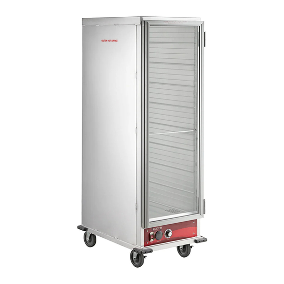
#177HEAT1836I
Full Size • Insulated • Clear Doors
#177HEAT1836
Full Size • Non-Insulated • Clear Doors
#177HTI1836DC Full Size • Insulated • Clear Dutch Doors
#177HTI1836DS Full Size • Insulated • Solid Dutch Doors
Warning:
Read and understand all INSTRUCTIONS before operating.
Failure to follow the safety rules and other basic safety
precautions may result in serious personal injury.
www.AvantcoEquipment.com
Service Manual
Holding/Proofing
Models:
#177HPI1812
Half Size • Insulated • Clear Doors
#177HPU1812
Half Size • Non-Insulated • Clear Doors
#177HPI1836
Full Size • Insulated • Clear Doors
#177HPU1836
Full Size • Non-Insulated • Clear Doors
#177HPI1836DC Full Size • Insulated • Clear Dutch Doors
#177HPI1836DS Full Size • Insulated • Solid Dutch Doors
A licensed and insured electrician or food service technician
is required to carry out any servicing on this equipment.
Please review all hazard statements in the user manual
before interacting or servicing this equipment.
11/2024
Advertisement
Table of Contents

Related Manuals for Avantco Equipment 177HEAT1836I


Summary of Contents for Avantco Equipment 177HEAT1836I
- Page 1 11/2024 Heated Holding Cabinets Holding Only Holding/Proofing Models: Models: #177HEAT1836I Full Size • Insulated • Clear Doors #177HPI1812 Half Size • Insulated • Clear Doors #177HEAT1836 Full Size • Non-Insulated • Clear Doors #177HPU1812 Half Size • Non-Insulated • Clear Doors #177HTI1836DC Full Size •...
-
Page 2: Table Of Contents
Service Manual Heated Holding Cabinets Table of Contents Troubleshooting . . . . . . . . . . . . . . . . . . . . . . . . . . . . . . . . . . . . .3 Part Replacement: Fan Motor Assembly . -
Page 3: Troubleshooting
Service Manual Heated Holding Cabinets Troubleshooting No Power • Check the building power and the breaker to outlet . • If the GFCI receptacle has tripped on initial power up or after long period Is the building power of not being used, plug the unit into a non-GFCI outlet with no water in functioning? well on high heat setting for 30-60 minutes . - Page 4 Service Manual Heated Holding Cabinets Troubleshooting Unit power on, no heat or low heat • Hold & Proof Cabinets: Set the selector switch to Is the Heat/Proof switch 'Heat' and turn thermostat above '0 . ' set to 'Heat' and/or the •...
-
Page 5: Access Points
Service Manual Heated Holding Cabinets Access Points Fig. 1 Fig. 2 Control Drawer Removal (Fig. 1) Remove the hanging rear panel inside the cabinet and set it aside . To remove, lift up on the handle at the top and pull it away from the wall (Fig . 2) . There are (4) keyholes on the panel that release from the screws when lifting up . -
Page 6: Operation Of Unit
Service Manual Heated Holding Cabinets Access Points Fig. 8 Control Drawer Bottom Panel Turn the drawer on its side . 2 . Remove the (10) Phillips screws from the bottom panel (Fig . 8) . 3 . Slide the bottom panel toward the rear of the drawer to expose the elements, fan motor, and wiring (Fig . -
Page 7: Part Testing: Power Switch
Service Manual Heated Holding Cabinets Parts Testing Fig. 10 Power Switch (Fig. 10) Ensure the unit is unplugged . 2 . Access the back of the switch panel to test the switch (Fig . 11) . 3 . Remove the wire leads from the switch noting their locations (Fig . -
Page 8: Part Testing: Thermostats
Service Manual Heated Holding Cabinets Part Testing Fig. 17 Thermostats (Fig. 17) Heat and Humidity thermostats are identical . 2 . With the unit off, remove the terminals from the back of the thermostat, noting their location (Fig . 18) . 3 . -
Page 9: Part Testing: Fan Motor Assembly
Service Manual Heated Holding Cabinets Part Testing Fig. 22 Fan Motor Assembly With power on, check for 0 .63 amps +/-10% on the black fiber-insulated wire . Be sure to clamp on the control panel side of the main baffle (Fig . 22 & 23) . If you clamp inside the motor box, the motor coils will throw off your meter and will show a higher amp draw . -
Page 10: Part Testing: Heating Elements
Service Manual Heated Holding Cabinets Part Testing Heating Elements Fig. 26 900W There is an inner 600W element loop and an outer 600W 900W element loop (Fig . 26) . NOTE: If the Heat/Proof switch is in 'Proof' mode and the heat thermostat is set above 0, the 600W LINE VOLTAGE HERE TO element will be hot and the 900W element will be PIN 2a OF POWER SWITCH... -
Page 11: Part Replacement: Power Switch
Service Manual Heated Holding Cabinets Part Replacement If repair is time-critical and part cost is not an issue, re- placing the control drawer is the easiest way to get the unit functional. Refer to the Access Points section of the manual for removal. -
Page 12: Part Replacement: Heat Thermostat
Service Manual Heated Holding Cabinets Part Replacement UNPLUG UNIT BEFORE REPLACING PARTS. CAUTION: SOME COMPONENTS MAY BE HOT. Heat Thermostat (Fig. 35) Fig. 35 Fig. 36 • NOTE: The humidity thermostat replacement will be shown in the proofing element section due to its probe location (see page 14) . -
Page 13: Part Replacement: Fan Motor Assembly
Service Manual Heated Holding Cabinets Part Replacement UNPLUG UNIT BEFORE REPLACING PARTS. CAUTION: SOME COMPONENTS MAY BE HOT. Fig. 42 Fan Motor Assembly With the front and bottom panels off, disconnect the motor wires . The white (N) wire will be the smaller gauge white wire in one of the two crimped together sets (Fig . -
Page 14: Part Replacement: Humidity Element
Service Manual Heated Holding Cabinets Part Replacement Fig. 46 UNPLUG UNIT BEFORE REPLACING PARTS. CAUTION: SOME COMPONENTS MAY BE HOT. Remove (2) end panel Humidity Element screws, this side. Before beginning, you will need (8) 1/8" pop rivets to reassemble the unit after changing the component . 2 . -
Page 15: Part Replacement: Door Gasket
Service Manual Heated Holding Cabinets Part Replacement Fig. 52 UNPLUG UNIT BEFORE REPLACING PARTS. CAUTION: SOME COMPONENTS MAY BE HOT. Door Gasket Remove the old gasket by pulling it out of the door channel (Fig . 52) . 2 . If the new gasket came in rolled up/wrinkled, soak it in hot water to remove wrinkles before installing . -
Page 16: Wiring Diagram: Heated Holding & Proofing Cabinet
Service Manual Heated Holding Cabinets Wiring Diagram Heated Holding & Proofing Cabinet www.AvantcoEquipment.com... -
Page 17: Wiring Diagram: Heated Holding Cabinet
Service Manual Heated Holding Cabinets Wiring Diagram Heated Holding Cabinet www.AvantcoEquipment.com... -
Page 18: Cabinet Assembly
Service Manual Heated Holding Cabinets Cabinet Assembly Full Size FOR MODELS: 177HPI1836, 177HPU1836, 177HEAT1836, 177HEAT1836I www.AvantcoEquipment.com... - Page 19 Service Manual Heated Holding Cabinets Cabinet Assembly Full Size FOR MODELS: 177HPI1836, 177HPU1836, 177HEAT1836, 177HEAT1836I Description Item # TOP SEALING PLATE* — TOP INSULATION* — TOP PANEL — FRONT TOP STOP BAR — MAGNETIC STRIP-TOP — FULL SIZE DOOR GASKET...
-
Page 20: Parts Diagram: Dutch Door Cabinets
Service Manual Heated Holding Cabinets Cabinet Assembly Full Size - Dutch Door FOR MODELS: 177HPI1836DC, 177HPI1836DS, 177HTI1836DC, 177HTI1836DS www.AvantcoEquipment.com... - Page 21 Service Manual Heated Holding Cabinets Cabinet Assembly Full Size - Dutch Door FOR MODELS: 177HPI1836DC, 177HPI1836DS, 177HTI1836DC, 177HTI1836DS Description Item # TOP SEALING PLATE* — TOP INSULATION* — TOP PANEL — FRONT TOP STOP BAR — MAGNETIC STRIP-TOP — SIDE SEALING PLATE* —...
-
Page 22: Parts Diagram: Half Size Cabinets
Service Manual Heated Holding Cabinets Cabinet Assembly Half Size FOR MODELS: 177HPU1812, 177HPI1812 14 15 www.AvantcoEquipment.com... - Page 23 Service Manual Heated Holding Cabinets Cabinet Assembly Half Size FOR MODELS: 177HPU1812, 177HPI1812 Description Item # TOP SEALING PLATE* — TOP INSULATION* — TOP PANEL — SIDE INSULATION* — LEFT SIDE PANEL — FRONT TOP STOP BAR — MAGNETIC STRIP-TOP —...
-
Page 24: Drawer Assembly
Service Manual Heated Holding Cabinets Drawer Assembly HCD1500H Drawer Diagram Holding Only ITEM: 177DRWRHEAT, HEATING/HOLDING DRAWER ASSEMBLY FOR MODELS: 177HTI1836DC, 177HTI1836DS, 177HEAT1836, 177HEAT1836I www.AvantcoEquipment.com... - Page 25 Service Manual Heated Holding Cabinets Drawer Assembly Holding Only ITEM: 177DRWRHEAT, HEATING/HOLDING DRAWER ASSEMBLY FOR MODELS: 177HTI1836DC, 177HTI1836DS, 177HEAT1836, 177HEAT1836I Description Item # DRAWER BODY — UPPER PROBE BRACKET — LOWER PROBE BRACKET — HI-LIMIT THERMOSTAT 177PHCD019 TRANSFORMER BRACKET —...
-
Page 26: Parts Diagram: Holding/Proofing Drawer
Service Manual Heated Holding Cabinets Drawer Assembly Holding/Proofing ITEM: 177DRWRHP, HOLDING/PROOFING DRAWER ASSEMBLY Drawer Assembly FOR MODELS: 177HPI1836, 177HPU1836, 177HPI1836DC, 177HPI1836DS, 177HPI1812, 177HPU1812 HCD1500 Drawer Diagram www.AvantcoEquipment.com... - Page 27 Service Manual Heated Holding Cabinets Drawer Assembly Holding/Proofing ITEM: 177DRWRHP, HOLDING/PROOFING DRAWER ASSEMBLY FOR MODELS: 177HPI1836, 177HPU1836, 177HPI1836DC, 177HPI1836DS, 177HPI1812, 177HPU1812 Description Item # REPLACEMENT WATER PAN COVER 177WTRPNCVR STAINLESS STEEL WATER PAN — DRAWER BODY — UPPER PROBE BRACKET —...
Need help?
Do you have a question about the 177HEAT1836I and is the answer not in the manual?
Questions and answers