Advertisement
AR-2001 AluRack Crossbar Module, 67" Kit
Page 2
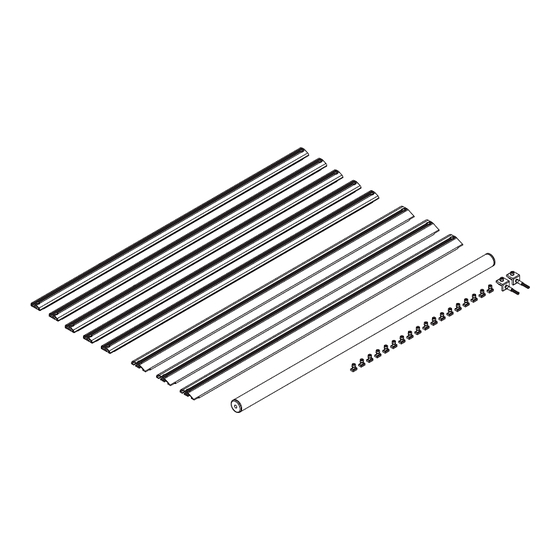
Packaging Contents
Page 3
Strip Nuts and Roller Bracket
Page 4–5
Crossbar Configurations
Page 5–6
Crossbar Installation
Page 6–7
Roller Installation
Page 7
Final Instructions
PRIME DESIGN, A SAFE FLEET BRAND ▪ Address: 1689 Oakdale Avenue #102, West St Paul, Minnesota 55118
Toll Free: 1.8.PRIME.RACK ▪ Fax: 651-552-1799 ▪ Email: info@primedesign.net ▪ Website: www.primedesign.net
Advertisement
Table of Contents

Related Manuals for Safe Fleet PRIME DESIGN AR-2001


Summary of Contents for Safe Fleet PRIME DESIGN AR-2001
- Page 1 Page 5–6 Crossbar Installation Page 6–7 Roller Installation Page 7 Final Instructions PRIME DESIGN, A SAFE FLEET BRAND ▪ Address: 1689 Oakdale Avenue #102, West St Paul, Minnesota 55118 Toll Free: 1.8.PRIME.RACK ▪ Fax: 651-552-1799 ▪ Email: info@primedesign.net ▪ Website: www.primedesign.net...
-
Page 2: Contents Overview
CONTENTS OVERVIEW AluRack Heavy Duty Crossbar ......(Qty 3) With hardware, 67.00” AluRack Standard Crossbar ......... (Qty 5) With hardware, 67.00” AluRack Roller Assembly ........(Qty 1) 63.75”, with Caps Crossbar and Roller Hardware ......(Qty 1) M8 Strip Nut (18X) M8 Lock Washer (18X) M8 Cap Head Bolt (18X) Roller Bracket (2X) - Page 3 STRIP NUT INSTALLATION ROLLER BRACKETS Install Roller Brackets into the rear most Strip Nuts, and align flush against the rear end of the Side Rail as shown. Torque Roller Bracket Bolts to 90 in-lbs. Cap Head Bolt Lock Washer Roller Bracket Prime Design Limited Warranty.
- Page 4 CROSSBAR CONFIGURATIONS Measurements are specified according to distances from the Side Rail rear ends. It is recommended to determine your Crossbar pattern before installing them into your Strip Nuts to ensure proper order of use. *The AluRack shown in Fig.1 is for Illustrative Purposes only, and your Configuration will vary. Refer to the table in Fig. 2 for your product-specific Configuration.
- Page 5 FRONT Crossbar Crossbar Crossbar Crossbar Crossbar Crossbar Crossbar Crossbar PRODUCT SIDE RAIL AR1910: Ford Transit L2H2 Flush to 10.75” 25.00” 39.25” 53.50” 67.75” 82.00” 96.25” *112.00” Front Side 130” Wheelbase, 101” Roof Height Rail End AR1911: Ford Transit L3H3 Flush to 5.25”...
- Page 6 LEFT SIDE RAILS AND CROSSBARS Install the Crossbars according to your configuration in the Strip Nuts as shown and torque to 90 in-lbs. NOTE: Rack shown is for Illustrative Purposes only. The order and placement of Standard Crossbars, Heavy Duty Crossbars, and Roller will vary as shown in Step 1, Fig.
-
Page 7: Roller Assembly
ROLLER ASSEMBLY Insert the Roller Tube Pin and Roller Tube Spring into the Roller ends. ROLLER INSTALLATION Insert the Roller Tube Pin on each side of the Roller Tube into the Brackets as shown. Prime Design Limited Warranty. Seller’s sole and exclusive warranty (and Buyer’s sole and exclusive remedy and Seller’s entire liability for any breach thereof) with respect to the Goods is set forth in the Limited Warranty document available at primedesign.net/warranty-liability (the “Prime Design Limited Warranty”). -
Page 8: Final Instructions
FINAL INSTRUCTIONS Do not mount the AluRack to an FBM system at this time. Refer to the respective FBM Assembly Manual(s) included with your chosen rack configuration features. WARNING: Failure to position the AluRack as shown in your FBM Assembly Manual may result in damage to the ladder rack. INSTALLER NOTE: To purchase applicable features and accessories, please contact your authorized distributor, or a Prime Design Sales &...
Need help?
Do you have a question about the PRIME DESIGN AR-2001 and is the answer not in the manual?
Questions and answers