Table of Contents
Advertisement
Quick Links
IGM LAGUNA Fusion 3 mod.2022 Table Saw
Manual
Producer
Laguna Tools Inc.
744 Refuge Way, Suite 200 Grand Prairie, Texas 75050
USA
Phone: +1 800-234-1976
Website:
www.lagunatools.com
Distributor
IGM nástroje a stroje s.r.o.
Ke Kopanině 560, 252 67, Tuchoměřice
Czech Republic, EU
Phone: +420 220 950 910
E-mail:
sales@igmtools.com
Website:
www.igmtools.com
2024-08-05
151-Fusion3Dro LAGUNA Table Saw Manual EN v4.02.01 A4ob
151-Fusion3Dro
Advertisement
Table of Contents

Related Manuals for IGM LAGUNA Fusion 3 mod.2022


Summary of Contents for IGM LAGUNA Fusion 3 mod.2022
- Page 1 151-Fusion3Dro IGM LAGUNA Fusion 3 mod.2022 Table Saw Manual Producer Laguna Tools Inc. 744 Refuge Way, Suite 200 Grand Prairie, Texas 75050 Phone: +1 800-234-1976 Website: www.lagunatools.com Distributor IGM nástroje a stroje s.r.o. Ke Kopanině 560, 252 67, Tuchoměřice Czech Republic, EU...
-
Page 2: Ec Declaration Of Conformity
EC-type Examination Certificate of MD (2006/42/EC) for update standards and additional issue Conformity Certificate of LVD (2014/35/EU) The person who compile technical file established within the EU: Name: IGM nastroje a stroje s.r.o. Address: Ke Kopanine 560, Tuchomerice, CZ-252 67 Tel.: +420 220 950 910 Email: sales@igmtools.com... -
Page 3: Table Of Contents
EN - English Operating Instructions Dear Woodworker, Thank you for your purchase and welcome to the Laguna Tools group of discerning woodworkers. We understand that you have a choice of where to purchase your machines and appreciate the confidence you have in the Laguna Tools brand. Every machine manufactured by Laguna Tools has been carefully designed and well thought through from a woodworker’s perspective. -
Page 4: Declaration Of Conformity
We declare that this product is in compliance with the directive and the standard mentioned on the 2. page of this manual. 1.1 Warranty IGM Tools & Machinery strives to always deliver high-quality machinery. The warranty is governed by the valid terms and conditions of IGM Tools & Machinery available at www.igmtools.com. -
Page 5: General Safety
Rip Fence Type Sliding Cam Action Fully Adjustable Fence Dimensions (LxWxH) 670 x 80 x 17 mm Throat Plate Type Professional Square Zero Clearance Throat Plate Dimensions (LxWxH) 372 x 104,5 x 13 mm Working Height (Floor to Table) 887 mm 4. -
Page 6: Tool Use
are not enough to ensure safety. • Check for damaged parts. Before every use of this tool, makes sure the machine and any components of the machine are not damaged or at the risk of being damaged. If a damaged part is discovered, stop immediately and put the machine out of service until the part is replaced. •... -
Page 7: Electrical
4.12 Notice on safe use The machinery sold by Laguna Tools, distributed by IGM Tools and machinery co., are safe when used properly and comply to with the CE norms, www.igmtools.com... -
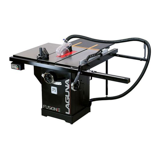
Page 8: Machine Overview
Laguna Tools or IGM is in no way responsible for injury or death that occurs while using this product. Your personal safety is 100% your responsibility and using this product requires 100% of your attention. -
Page 9: Setup
Arbor height control The arbor height control adjusts the height of the blade. In the middle is the height adjustment lock. Behind the control is the tile gauge. Clockwise to raise, counter-clockwise to lower blade. CAUTION: DO NOT ADJUST HEIGHT WHEEL WHEN LOCKED. Arbor tilt control The tilt control, located on the right of the cabinet, adjusts the tilt of the arbor. -
Page 10: Inventory
Receiving your table saw This is how machine is shipped from the factory. Unscrew the crate fasteners Use a drill with a #2 Phillips head bit and remove the bottom screws from carton. These screws may be discarded. Lift crate off pallet Use two persons to lift the carton away from the pallet. -
Page 11: Loose Parts & Overview
Hardware kit Rear Rail 1 Front Rail 1 Pre-installed on machine Throat plate Riving knife 250mm blade Mitre fence Arbor wrench Tool storage Wings (2x) Note: The front rail part number is comprised of two pieces – both long and short. The rear rail part number is comprised of two pieces – long and short. Note: For safety reasons, this machine is not sold with a tape-rule for the left side of the blade. - Page 12 NOTICE: If the fence hooks are not yet installed, now is a good time to do so. 3. Level the rear rails and fasten To level the rear fence with the table top, place a rigid straight edge on top of the rails. Apply downward force at both arrow indicators and simultaneously tighten the bolts with the supplied Allen key and wrench.
-
Page 13: Installing/Removing The Throat Plate
9. Level and fasten front rail To level the front rail sections to the table top, use a ridged straight edge atop the loosely fit rail sections. Apply downward force to the straight edge while keeping the two sections firmly together. Simultaneously fasten down the bolts. 10. -
Page 14: Installing/Removing Safety Accessories
Installing the throat plate WARNING: MAKE SURE SAW IS UNPLUGGED. To remove or install the throat plate, first set it to the unlock position. Then, insert the rear end first and tilt the other end down into position. Levelling the throat plate To level the throat plate, adjust the leveling screws. - Page 15 Note on the blade Installing the riving knife Unplug the table saw! Make sure the lock is in open position. Insert the riving knife with blade guard. Make sure the riving knife is correctly positioned. Lock the riving knife. Reinstall throat plate. CAUTION: Make sure the blade guard is in line with the blade.
-
Page 16: Installing The Blade
Grasp the blade guard and insert the throat plate. Lock the throat plate. CAUTION: Make sure the riving knife is in-line with the blade. If it is not in line, please see the Adjustments section. 6.7 Installing the Blade 1. Unplug the table saw! 2. -
Page 17: Adjustments
6. Remove arbor nut and flange 7. Adjustments Your Laguna Tools machine comes fully adjusted from the factory, but it is good practice to double check these adjustments and make sure the tool is in safe operating condition. 7.1 Rip fence Adjustments Fitting the fence: You will need to fit the fence to the right side of the blade to use the table saw. -
Page 18: Adjusting The Fence Glide Bushings
4. Adjust the viewport Use a #2 Philips head driver to loosen (but do not remove) the transparent scale reader. Adjust the viewport as needed, tighten the screws. Note: If adjusting the viewport does not allow enough to zero the scale, see step 8 of machine setup. Note: There are 2 viewports on the rip fence to adjust material width according to the position of the aluminum profile - vertically or horizontally. -
Page 19: Mitre Fence Setting
3. Use a hex key to adjust Use the included hex key to adjust the depth of each nylon support. Do small increments and check. 7.2 Mitre fence setting The mitre fence can be set from +60° to -60°. You can set the desired cutting angle by releasing the handle and loosening the control screw on the front of the fence. - Page 20 2. Take initial measurement WARNING: MAKE SURE SAW IS UNPLUGGED. With the throat plate and all attachments removed, raise the blade to the highest position at 90 degrees with the table. Take an initial measurement about 1 cm from the ground edge of the blade as shown. 3.
-
Page 21: Arbor And Tilt Adjustments
2. Clamp support to the table WARNING: MAKE SURE SAW IS UNPLUGGED. Clamp two wooden supports to the underside of the table saw as shown. Use solid, straight boards. 3. Place extension wing on supports Place the extension wing on the supports and place into position. Join or adjust wing You will need (4) M10 bolts and (4) washers to fasten each extension wing to the table. -
Page 22: Adjusting The Belt
4. Locate tilt adjustment screw Locate tilt adjustment screw. Screw it in to expand the tilt range slightly. 5. Adjust as needed Locate the tilt adjustment screw. Screw it in to expand the tilt range slightly. 6. Adjust scale (if needed) Adjust the scale and tilt indicator on the cabinet if needed. -
Page 23: Changing The Belt
Changing the belt: 1. Unplug the table saw! 2. Remove all throatplates, blades, and blade accessories. 3. Remove the motor cover. 4. Remove the dust shroud. 5. Loosen the belt adjustment bolt and loosen belt by raising motor. 6. Remove belt. NOTE: you may need to lower the arbor height to access the belt. 7. -
Page 24: Dust Collection
As adjustments are made, the blade attachments will translate, not rotate, by design. This ensures that the workpiece will not get held up. CHECK COMPONENTS BEFORE EVERY CUT. Riving knife adjustments: After changing a saw blade, always check that the riving knife is correctly set! The distance of the riving knife from the gear rim must be between 3 mm and 8 mm. -
Page 25: Types Of Cut
A push block (Fig.2, not included) and push stick (Fig.3, included) must be used when working. If the workpiece is less then 120 mm wide, use the push stick as a safety measure. Push block should be used to cut narrow workpieces and to push the workpiece against the fence. -
Page 26: Ripping Small Workpieces
8.3 Ripping small workpieces Do not attempt rip cuts if the work piece is too small, as this will oblige you to place your hands too close to the blade and put you at serious risk of injury. When ripping narrower widths; use a push block or a push stick in order to avoid placing hands near the blade. 8.4 Cross cutting Cutting against the grain, to shorten the length of a board is crosscutting. -
Page 27: Troubleshooting
Lubricate gearing and gearboxes. • 9.1 Internal Components Map A. Motor B. Dust Shroud C. Trunnion Slides (Support) D. Upper Trunnion E. Lower Trunnion F. Arbor Nut G. Arbor Washer (Flange) H. Blade I. Tilt Gearing J. Height Gearing K. Belt L. - Page 28 11. Wiring diagram and parts list Wiring diagram: Fusion3Dro 230 V www.igmtools.com...
-
Page 29: Parts Breakdown
Parts breakdown www.igmtools.com... - Page 30 Mitre fence, blade guard www.igmtools.com...
-
Page 31: Motor And Trunnion
Motor and trunnion www.igmtools.com... - Page 32 Cabinet www.igmtools.com...
-
Page 33: Parts List
Parts list www.igmtools.com...
Need help?
Do you have a question about the LAGUNA Fusion 3 mod.2022 and is the answer not in the manual?
Questions and answers