Table of Contents
Advertisement
Quick Links
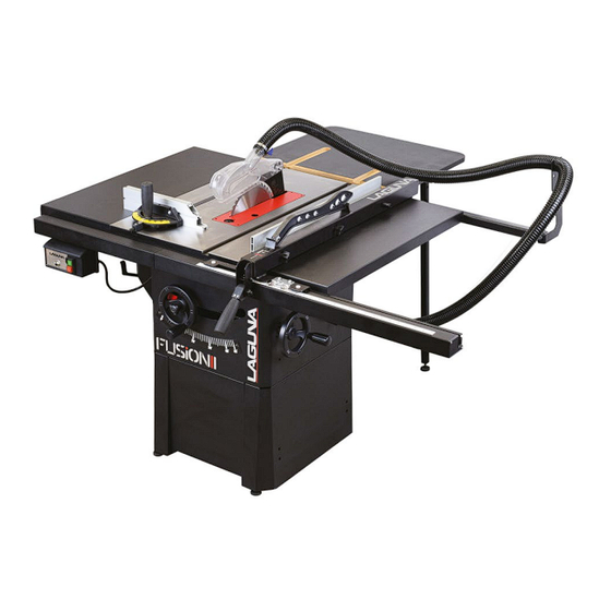
IGM LAGUNA Fusion 1 Table Saw
Manual
Producer
Laguna Tools Inc.
744 Refuge Way, Suite 200 Grand Prairie, Texas 75050
USA
Phone: +1 800-234-1976
Website:
www.lagunatools.com
Distributor
IGM nástroje a stroje s.r.o.
Ke Kopanině 560, 252 67, Tuchoměřice
Czech Republic, EU
Phone: +420 220 950 910
E-mail:
sales@igmtools.com
Website:
www.igmtools.com
2024-08-05
151-Fusion2 LAGUNA Table Saw Manual EN v5.02.01 A4ob
151-Fusion1
Advertisement
Table of Contents

Related Manuals for IGM LAGUNA Fusion 1


Summary of Contents for IGM LAGUNA Fusion 1
- Page 1 151-Fusion1 IGM LAGUNA Fusion 1 Table Saw Manual Producer Laguna Tools Inc. 744 Refuge Way, Suite 200 Grand Prairie, Texas 75050 Phone: +1 800-234-1976 Website: www.lagunatools.com Distributor IGM nástroje a stroje s.r.o. Ke Kopanině 560, 252 67, Tuchoměřice Czech Republic, EU...
-
Page 2: Ec Declaration Of Conformity
EC-type Examination Certificate of MD (2006/42/EC) for update standards and additional issue Conformity Certificate of LVD (2014/35/EU) The person who compile technical file established within the EU: Name: IGM nastroje a stroje s.r.o. Address: Ke Kopanine 560, Tuchomerice, CZ-252 67 Tel.: +420 220 950 910 Email: sales@igmtools.com... -
Page 3: Table Of Contents
EN - English Operating Instructions Dear Woodworker, Thank you for your purchase and welcome to the Laguna Tools group of discerning woodworkers. We understand that you have a choice of where to purchase your machines and appreciate the confidence you have in the Laguna Tools brand. Every machine manufactured by Laguna Tools has been carefully designed and well thought through from a woodworker’s perspective. -
Page 4: Declaration Of Conformity
We declare that this product is in compliance with the directive and the standard mentioned on the 2. page of this manual. 1.1 Warranty IGM Tools & Machinery strives to always deliver high-quality machinery. The warranty is governed by the valid terms and conditions of IGM Tools & Machinery available at www.igmtools.com. -
Page 5: General Safety
Blade Diameter 250 mm Blade Bore Diameter 30 mm Arbor Speed 3800 rpm Blade Rotation Counter-Clockwise Max. Rip Capacity 765 mm Right (1320,8 with Extension), 300 mm Left Max. Depth of Cut at 90° 79 mm Max. Depth of Cut at 45° 56 mm Blade Tilt 45°... -
Page 6: Tool Use
situations. • Dress properly. do not wear loose clothing or jewellery. Keep your hair and clothing away from moving parts. Loose clothes, jewellery or long hair can be caught in moving parts. • If devices are provided for the connection of dust extraction and collection facilities, ensure these are connected and properly used. Use of dust collection can reduce dust-related hazards. -
Page 7: Work Related Warnings
Use the appropriate saw blade for the riving knife. For the riving knife to function properly, the saw blade diameter must match the • appropriate riving knife and the body of the saw blade must be thinner than the thickness of the riving knife and the cutting width of the saw blade must be wider than the thickness of the riving knife. -
Page 8: Electrical
4.12 Notice on safe use The machinery sold by Laguna Tools, distributed by IGM Tools and machinery co., are safe when used properly and comply to with the CE norms, standards and regulations for safe use. Laguna Tools or IGM is in no way responsible for injury or death that occurs while using this product. -
Page 9: Machine Overview
Disconnect from power supply before servicing. Fully read manual and safety instructions before use. Safety gloves should be worn. 5. Machine Overview 1. Start / Stop 2. Rip Fence 3. Fence Front guide 4. Fence Rear guide 5. Table with mitre slots 6. -
Page 10: Setup
The tilt control, located on the right of the cabinet, adjusts the tilt of the arbor. Clockwise to tilt left, counter-clockwise to tilt the blade to the right. Fence clamp lock The fence clamp securely locks the fence anywhere on the rail by a cam action mechanism. 6. -
Page 11: Inventory
Wipe off protective layer Peel back the protective layer and wipe away the oil with a waste rag. Use caution: An oily rag can be a serious fire hazard. Discard in an appropriate manner. Tech Tip: To help keep your table top clean and to prevent or clean any rust, we recommend waxing your tabletop with an appropriate wax rubbing compound. -
Page 12: Machine Setup
M8x1.5 + lock washer + washer + nut Square head 8x1.5 + washer + nut Fence hooks (step 2) 6.4 Machine Setup Assemble the base. Attach extension wings. Attach the short rear fence support Attach the long rear fence support Level the rear rails and fasten Attach T-Slot bolts to front table Insert long front rail fence support... - Page 13 5. Level the rear rails and fasten To level the rear fence with the table top, place a rigid straight edge on top of the rails. Apply downward force at both arrow indicators and simultaneously tighten the bolts with the supplied Allen key and wrench. 6.
-
Page 14: Installing/Removing The Throat Plate
11. Level and fasten front rail To level the front rail sections to the table top, use a ridged straight edge atop the loosely fit rail sections. Apply downward force to the straight edge while keeping the two sections firmly together. Simultaneously fasten down the bolts. 12. - Page 15 C: Cam action lever D: Riving knife E: Blade guard F: Blade compliant markings Note on the riving knife Warning: Since Riving Knife, other than those offered by Laguna, has not been tested with this product, use of such accessories with this tool could be hazardous.
-
Page 16: Installing The Blade
3. Insert the riving knife WARNING: MAKE SURE SAW IS UNPLUGGED. With the throat plate removed, and the cam lock mechanism in the open position (pulled up), insert the riving knife into the slot. 4. Position to the left of casing Carefully insert the riving knife into the slot and push down. -
Page 17: Adjustments
4. Raise saw blade to highest position. Engage blade lock (red lever). Remove the arbor nut. Remove or install blade. CAUTION: Make sure the teeth of the blade are facing the front of the saw as shown. 2. Remove all accessories WARNING: MAKE SURE SAW IS UNPLUGGED. -
Page 18: Rip Fence Adjustments
sure the tool is in safe operating condition. 7.1 Rip fence Adjustments Fitting the fence: You will need to fit the fence to the right side of the blade to use the table saw. You will need to fit the fence to the right side of the blade to use the table saw. - Page 19 Use a #2 Philips head driver to loosen (but do not remove) the transparent scale reader. Adjust the viewport as needed, tighten the screws. Note: If adjusting the viewport does not allow enough to zero the scale, see step 8 of machine setup. Note: There are 2 viewports on the rip fence to adjust material width according to the position of the aluminum profile - vertically or horizontally.
-
Page 20: Mitre Fence Setting
Use the included hex key to adjust the depth of each nylon support. Do small increments and check. 7.2 Mitre fence setting The mitre fence can be set from +60° to -60°. You can set the desired cutting angle by releasing the handle and loosening the control screw on the front of the fence. -
Page 21: Changing The Belt
2. Remove motor cover WARNING: MAKE SURE SAW IS UNPLUGGED. To access the left side tilt limit adjustment screw, remove the motor housing cover using a #2 Philips head driver. There are 4 screws in total holding on the motor cover. 3. - Page 22 5. Remove dust hood. 6. Remove fixing plate. 7. Turn arbor height control to remove the belt. 8. Reverse the steps and reassemble. Use Caution: DO NOT OVERTIGHTEN BELT! The weight of the motor is adequate to put enough tension on the belt. Only tight enough to prevent slippage.
-
Page 23: Accessory Adjustments
6. Remove fixing plate 7. Lower the arbor about 50 mm by turning the arbor height control. Remove the belt. 8. Place the belt on the upper arbor and drive it upwards to prevent the belt from falling out. It is now easier to reach the lower arbor. Rotate the arbor to gradually thread the belt onto the lower arbor. -
Page 24: Dust Collection
As adjustments are made, the blade attachments will translate, not rotate, by design. This ensures that the workpiece will not get held up. CHECK COMPONENTS BEFORE EVERY CUT. Riving knife adjustments: After changing a saw blade, always check that the riving knife is correctly set! The distance of the riving knife from the gear rim must be between 3 mm and 8 mm. -
Page 25: Types Of Cut
A push block (Fig.2, not included) and push stick (Fig.3, included) must be used when working. If the workpiece is less then 120 mm wide, use the push stick as a safety measure. Push block should be used to cut narrow workpieces and to push the workpiece against the fence. -
Page 26: Digital Read-Out Calibration
After changing the bevel angle verify the alignment of the guard and splitter; make sure there is clearance with the saw blade. Digital read-out calibration Step 1: Set the wheel perpendicular to the table. There is 0° on the scale. Press ZERO to reset, 0.0 will be displayed. Step 2: Turn the wheel to set 45°, press and hold the SET button. -
Page 27: Troubleshooting
Clean table surface and mitre slot • • Clean cast-iron parts Clean rip fence • Check monthly for: Dust buildup from inside cabinet and off motors. • • Belt for proper tension, damage or wear. Every 6–12 Months: • Lubricate trunnion slides. Lubricate worm gear. -
Page 28: Wiring Diagram And Parts List
Wiring should only be done by professional electricians. Always make sure the machine is properly earthed. All exposed conductive parts should be connected to the protective bonding circuit. Close and lock the door of cabinets. WARNING: Enough space around the machine and the cabinets should be kept in order to maintain conveniently. The machine should be installed in a workshop with good illumination and ventilation. - Page 29 www.igmtools.com...
-
Page 30: Parts List
Parts list 102 381463-901 Fix Bushing 925200-000 Fence Assembly L\H (800mm) 924708-000 Blade Guard Assembly US Type 103 000304-113 Pan Head Screw M6*1.0P*30 924562-001 Miter Gauge Assembly 104 174789-000 Motor Cover 051437-000 Extension Table 105 051135-000 Trunnion Support 011001-103 Spring Pin 3*10 106 000003-104 Hex.
Need help?
Do you have a question about the LAGUNA Fusion 1 and is the answer not in the manual?
Questions and answers