
Subscribe to Our Youtube Channel
Related Manuals for KoolMore KM-MOTC-15SS


Summary of Contents for KoolMore KM-MOTC-15SS
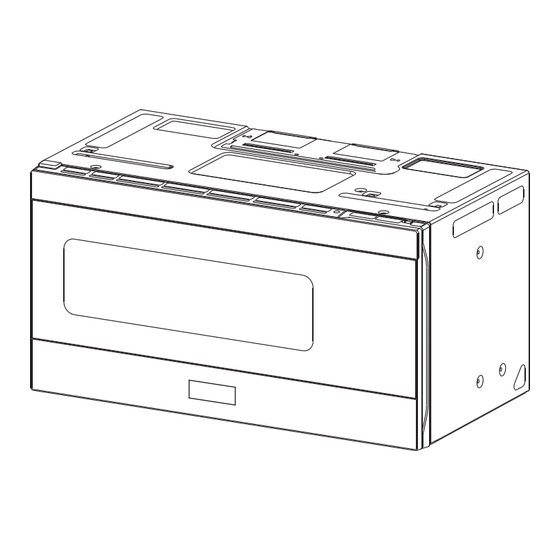
- Page 1 INSTALLATION MANUAL KoolMore Over the Range Convection Microwave Oven Model: KM-MOTC-15SS...
- Page 2 Stay informed with the latest information for your KoolMore Appliance. If you need any assistance or have questions, our customer support team is here to help.
-
Page 3: Electrical Requirements
SAFETY This product requires a three-prong grounded outlet. The installer must perform a ground continuity check on the power outlet box before beginning the installation to ensure that the outlet box is properly grounded. If not properly grounded, or if the outlet box does not meet electrical requirements noted (under ELECTRICAL REQUIREMENTS), a qualified electrician should be employed to correct any deficiencies. -
Page 4: Parts Included
DAMAGE—SHIPMENT/INSTALLATION ADDITIONAL PARTS If the unit is damaged in shipment, return the PART QUANTITY unit to the store in which it was bought for repair or replacement. C ombined T If the unit is damaged by the customer, repair C abinet T emplateand or replacement is the responsibility of the R ear Wall... -
Page 5: Mounting Space
MOUNTING SPACE Bottom edge of cabinet needs to be 30 (76.2 cm) or more fromthe NOTES: Cooking surface “ (33 cm) 13 Maximum “ (41.9 cm) ⁄ “ “ (76.2 cm) The space between the cabinets must be (76.2 cm) min. -
Page 6: Aligning The Wall Plate
C. DETERMINING WALL PLATE LOCATION UNDER YOUR CABINET Plat e posit ion—beneat h fram ed recessed Plat e p osit io n -beneat h f lat b ot t om Plate position-beneath cabinet bot t om cabinet flat bottom cabinet Ensure there is at least 30"... -
Page 7: Installation Types
2. INSTALLATION TYPES (Choose A, B or C) This microwave oven is designed for adaptation to the following three types of ventilation: A. Outside Top Exhaust (Vertical Duct) B. Outside Back Exhaust (Horizontal Duct) C. Recirculating (Non-Vented Ductless) NOTE: This microwave is shipped assembled for Recirculating. Select the type of ventilation required for your installation and proceed to that section. - Page 8 INSTALLATION INSTRUCTIONS FOR EXTERNAL EXHAUST DUCTING NOTE: If you need to install ducts, note that the total duct length of 3¾" x 10" (8.2 x 25.4 cm) rectangular or 5" (10.5 cm) diameter / 6" (15.2 cm) diameter round duct should not exceed 120 equivalent feet (36.5 m). Outside ventilation requires a EXTERNAL EXHAUST DUCT.
-
Page 9: Outside Top Exhaust (Example Only)
EXTERNAL EXHAUST DUCTING NOTE: Read these next two pages only if you plan to vent your exhaust to the outside. If you plan to recirculate the air back into the room, proceed to page 20. OUTSIDE TOP EXHAUST (EXAMPLE ONLY) The following chart describes an example of one possible ductwork installation. -
Page 10: Aoutside Top Exhaust
OUTSIDE TOP EXHAUST (Vert ical Duct ) INSTALLATION OVERVIEW A1. Attach Mounting Plate to Wall A2. Prepare Top Cabinet A3. Adapting Microwave Blower for Outside Top Exhaust 3/8" TO EDG E wall tem pla te along the dotted line. Trim the rear 12"... - Page 11 A2. USE TOP CABINET TEMPLATE FOR PREPARATION OF TOP CABINET You need to drill holes for the top support screws, a hole large enough for the power cord to t through, and a cutout large enough for the exhaust adaptor. Read the instructions on the TOP CABINET TEMPLATE.
-
Page 12: Mount The Microwave Oven
M OUNT THE M ICROWAVE ADAPTING M ICROWAVE OVEN BLOWER FOR OUTSIDE TOP EXHAUST Secure blower unit to microwave with the screw removed in Step1. Make sure the screw is tight. Replace blower plate with thescrew removed in Step1. Make sure the screw is tight. FOR EASIER INSTALLATION AND PERSONAL SAFETY,WERE COMMEND THAT TWO PEOPLE INSTALL THIS MICROWAVE OVEN. -
Page 13: Adjust The Exhaust Adaptor
M OUNT THE M ICROWAVE ADJUST THE EXHAUST OVEN (cont .) ADAPTOR Open the top cabinet and adjust the exhaust adaptor C abinet F ront to connect to the house duct. C abinet BottomShelf F iller Block Back of Damper Blower P late Microwave E quivalent... -
Page 14: Boutside Back Exhaust
OUTSIDE BACK EXHAUST (Horizont al Duct ) INSTALLATION OVERVIEW B1. Prepare Rear Wall B2. Remove Blower Plate B3. Attach Mounting Plate to Wall B4. Prepare Top Cabinet B5. Adjust Blower 3/8" TO EDG E pla te along the dotted lin e. Trim t he rear wal l t em 12"... -
Page 15: Adapting M Icrowave Blower For Outside Back Exhaust
You need to drill holes for the top support screws and ATTACH THE M OUNTING a hole large enough for the power cord to fit through. PLATE TO THE WALL • Read the instructions on the TOP CABINET TEMPLATE. • Attach the plate to the wall using toggle bolts. - Page 16 Roll the blower unit 90° Place the blower unit back into the opening. Before R otation After R otation AFTER: Fan Blade Openings Facing Back E nd A E nd B Back of Back of Microwave Microwave Rotate blower unit counterclockwise 180°. CAUTI ON: Do not pull or stretch the blower unit wiring.
- Page 17 C abinet F ront M OUNT THE M ICROWAVE C abinet BottomShelf OVEN F iller Block E quivalent to Depth of C abinet R ecess Self-Aligning Screw FOR EASIER INSTALLATION AND PERSONAL Microwave O ven T op SAFETY , WE RECOMMEND THAT TWO PEOPLE Attach the microwave oven to the top cabinet.
-
Page 18: Use Top Cabinet Tem Plate For Preparation Of Top Cabinet
RECIRCULATING (Non-Vent ed Duct less) INSTALLATION OVERVIEW C1. Attach Mounting Plate to Wall C2. Prepare Top Cabinet C3. Check Blower Plate 3/8" T O E DGE Tri m the rea r wall templa te along the dotted line. 12" NO T E : IT IS V ER Y IMP OR TA NT T O R EA D AND F O LL OW T HE D IRE C T IO NS... -
Page 19: Check Blower Plate
CHECK BLOWER PLATE NOTE: When mounting the microwave oven, thread power cord through hole in Blower P late bottom of top cabinet. Keep it tight throughout Steps Lift microwave, tilt 1–3. Do not pinch cord or it forward, and hook lift oven by pulling cord. - Page 20 M OUNT THE M ICROWAVE C5. INSTALLING OR CHANGE OVEN (cont .) THE CHARCOAL FILTER Insert 2 self-aligning screws NOTE: The charcoal filter is factory installed in through outer top cabinet recirculating models. Follow these steps to replace a holes. Turn two full turns on filter or to install a filter after converting a vented each screw.
-
Page 21: Before You Use Your Microwave
BEFORE YOU USE YOUR M ICROWAVE Make sure the microwave oven has been Read the Manual. U SE CARE & installed according to instructions. KEEP INSTALLATION INSTRUCTIONS Remove all packing material from the FOR THE LOCAL INSPECTOR’S microwave oven. USE. Install turntable ring and glass tray in cavity Replace house fuse or turn breaker back on. - Page 22 3/8" TO EDGE 12" Trim the rear wall template along the dotted line. NOTE: IT IS VERY IMPORTANT TO READ AND FOLLOW THE DIRECTIONS IN THE INSTALLATION INSTRUCTIONS BEFORE PROCEEDING WITH THIS REAR WALL TEMPLATE. This Rear Wall Template serves to position the bottom 4"...
Need help?
Do you have a question about the KM-MOTC-15SS and is the answer not in the manual?
Questions and answers