
Related Manuals for ABB ABB-free@home OneTouch 7 M2249-2 Series


Summary of Contents for ABB ABB-free@home OneTouch 7 M2249-2 Series
- Page 1 Product manual │ 23.08.2024 ABB-free@home ® M2249-2x ABB OneTouch 7 Branding -- Release 2018-01-01...
-
Page 2: Table Of Contents
Table of contents Table of contents Notes on the instruction manual ........................5 Safety ................................6 Information and symbols used ......................6 Intended use ............................7 Improper use ............................7 Target group / Qualifications of personnel ..................8 2.4.1 Operation ............................. 8 2.4.2 Installation, commissioning and maintenance ................ - Page 3 Table of contents Configuration via ABB-free@home ® ......................37 Allocation of devices and definition of channels ................37 9.1.1 Add device ..........................38 Setting options per channel ......................40 9.2.1 Parameter settings of panel......................41 9.2.1.1 Parameter settings Channel ................ 45 9.2.1.2...
- Page 4 Table of contents Update ............................... 102 Addressing ..............................103 Maintenance .............................. 104 13.1 Cleaning ............................104 Notes ................................105 Index ................................106 Product manual 2CKA000073B0036 │4...
-
Page 5: Notes On The Instruction Manual
If you pass the device on, also include this manual along with it. ABB accepts no liability for any failure to observe the instructions in this manual. If you require additional information or have questions about the device, please contact ABB or visit our Internet site at: https://new.abb.com/en... -
Page 6: Safety
However, residual hazards remain. Read and adhere to the safety instructions to prevent hazards of this kind. ABB accepts no liability for any failure to observe the safety instructions. Information and symbols used The following Instructions point to particular hazards involved in the use of the device or provide... -
Page 7: Intended Use
Each use not listed in Chapter 2.2 “Intended use“ on page 7 is deemed improper use and can lead to personal injury and damage to property. ABB is not liable for damages caused by use deemed contrary to the intended use of the device. The associated risk is borne exclusively by the user/operator. -
Page 8: Target Group / Qualifications Of Personnel
Safety Target group / Qualifications of personnel 2.4.1 Operation No special qualifications are needed to operate the device. 2.4.2 Installation, commissioning and maintenance Installation, commissioning and maintenance of the device must only be carried out by trained and properly qualified electrical installers. The electrical installer must have read and understood the manual and follow the instructions provided. -
Page 9: Cyber Security
Connection to the Internet or the local IP network To prevent improper use, no router ports from the Internet into the building network or home network are to be opened to the ABB OneTouch 7. A VPN tunnel is suitable for safe remote control. -
Page 10: Communication Protocols
The product is not susceptible to malware, because a user-defined code cannot be executed on the system. The only option of updating the software is the update of the firmware. Only a firmware signed by ABB is accepted. Transfer of the installation / decommissioning of the device If you are transferring the installation or decommissioning the device, remove the device from all access options and ensure that your user data are deleted by resetting to the factory settings. -
Page 11: Ports And Services For Supporting The Main Functionality
Safety 2.5.1 Ports and services for supporting the main functionality To support the main functionalities of the device, communication via specific ports and services must be possible in your local network. Contact your network administrator to set up, if necessary, the appropriate port sharing. Attention! Enabling the port increases the risk of cyber attacks. -
Page 12: Safety Instructions
Safety Safety instructions Danger - Electric voltage! Electric voltage! Risk of death and fire due to electric voltage of 100 … 240 V. Dangerous currents flow through the body when coming into direct or indirect contact with live components. This can result in electric shock, burns or even death. -
Page 13: Information On Protection Of The Environment
Information on protection of the environment Information on protection of the environment Environment Consider the protection of the environment! Used electric and electronic devices must not be disposed of with domestic waste. – The device contains valuable raw materials which can be recycled. Therefore, dispose of the device at the appropriate collecting depot. -
Page 14: Product Overview
The touch panel is linked with the wireless free@home devices and the ABB-Welcome ® bus. The audio/video signals are transmitted and the power for the device is supplied via the ABB- Welcome ® 2-wire system controller or via a separate 24V/DC power adaptor (CP-D 24/2.5). -
Page 15: Scope Of Supply
The special Surface-mounted mounting frame (ST/A10.1-xxx) and the associated Flush- mounted installation box (6136/07 UP-500; windproof) are not included in the scope of supply. The necessary power supply depends on the application (with or without integration into ABB- Welcome ®... -
Page 16: Functional Overview
Product Overview Functional overview The following table provides an overview of the possible functions and applications of the device: Functions Applications Switching Door communication ■ ■ Dimming Fault and alarm messages ■ ■ Venetian blind control Internal RTC ■ ■ RGBW operation Ledvance lamps and socket outlets ■... -
Page 17: Device Overview
Product Overview Device overview Device overview (front side) Fig. 2: Device overview ABB OneTouch 7 front side Pos. Description Touch screen Device overview (rear side) a1 b DC+ GND Station X100 X 00 P/SRC (PoE) Fig. 3: Device overview ABB OneTouch 7 rear side Pos. -
Page 18: Technical Data
Mains supply: 20 V - 30 V DC Standby operation: 24 V DC, 300 mA Nominal voltage: 24 V DC, 400 mA ® ABB-Welcome bus voltage 21 V - 32 V DC Energy consumption (power input) maximum: < 12 W ■... - Page 19 Technical data Designation Value 2412 ... 2472 MHz (for Europe) WLAN frequency range: 802.11a/n/ac: 5150…5250 MHz 5250…5350 MHz 5470…5725 MHz 5725…5850 MHz (for United States) Maximum transmission power, WLAN < 20 dBm Operating temperature 0°C - +45°C Storage temperature -25°C - +70°C Commissioning Via SAP-S-1-84, SAP-S-2,SAP/S.3 from Firmware Parameter setting: Programming (free@home)
-
Page 20: Dimensional Drawings
Technical data Dimensional drawings 1 .2 Fig. 4: Dimensions All dimensions are in millimetres. The installation height of the device is 14 mm. The installation depth is 10 mm. Notice The dimensions of the associated flush-mounted installation boxes (not included in the scope of supply) are as follows: Dimension for flush-mounting (H x W x D): 108 x 178 x 52 ■... -
Page 21: Circuit Diagrams
Electrical connection (rear side of device) Pos. Function Doorbell connector Temperature sensor connection (E.g. PT100) ABB-Welcome ® bus connection Connection for local power supply Outdoor station selector switch Setting the address of the default outdoor station Indoor station selector switch Selector switch X10 sets tens digits, selector switch X1 sets ones digits, DIP switches X100 and X200 set hundreds digits. -
Page 22: Connection, Installation / Mounting
® ® manuals for ABB-Welcome and ABB-free@home . These can be downloaded via https://new.abb.com/en or https://abb.com/freeathome. Safety instructions Danger - Electric voltage! Risk of death due to electrical voltage of 100 … 240 V during short-circuit in the low-voltage conduit. -
Page 23: Preparatory Steps
Connection, installation / mounting Preparatory steps Terminate all branches of the wiring system with a connected bus device (e.g., indoor ■ station, outdoor station, system device). Do not install the central control system directly next to bell transformers and of other ■... -
Page 24: Mounting / Dismantling
Connection, installation / mounting Mounting / dismantling 6.5.1 Installation sites Fig. 6: Installation sites When selecting the installation location, ensure that there is a distance to sources of heat or ■ cold. Heat or cold sources influence the function of the internal temperature sensor. ■... -
Page 25: Mounting
Connection, installation / mounting 6.5.2 Mounting The device is suited for flush-mounted and surface-mounted installation. The surface-mounted mounting frame (ST/A10.1-811; not part of the scope of supply) can be used for surface mounting when the device is not mounted on the associated flush-mounted installation box. -
Page 26: Mounting In Flush-Mounted Installation Box In Solid Wall
Connection, installation / mounting 6.5.3 Mounting in flush-mounted installation box in solid wall Installation on the basis of the instructions on the enclosed plastering template: Notice See mounting instructions on the enclosed plaster and drilling template. First the bottom part of the flush-mounted installation box must be pulled off and installed flush-mounted. -
Page 27: Mounting In Flush-Mounted Installation Box In Hollow Wall
Connection, installation / mounting 6.5.4 Mounting in flush-mounted installation box in hollow wall Installation on the basis of the instructions on the enclosed drilling template: Notice See mounting instructions on the enclosed plaster and drilling template. The bottom part of the flush-mounted installation box is not required here. Fig. -
Page 28: Mounting With Surface-Mounted Mounting Frame
Connection, installation / mounting 6.5.5 Mounting with surface-mounted mounting frame First, the surface-mounted mounting frame must be installed according to the following specification. Fig. 10: Installation of surface-mounted mounting frame Notice For additional information see the enclosed mounting instructions for surface- mounted mounting frames. -
Page 29: Electrical Connection
Connection, installation / mounting Electrical connection 6.6.1 Connection, installation and addressing a1 b DC+ GND (PoE) Station a1 b DC+ GND Station X 100 X 00 P / S R C (PoE) X100 X 00 P/S RC Fig. 12: Overview of connections / switches Product manual 2CKA000073B0036 │29... - Page 30 Connection, installation / mounting The connections, the switches and the terminal resistor are located on the rear of the ABB OneTouch 7. a1 b DC+ GND (PoE) Fig. 13: Overview of connections 1. Connect the device according to the graphics (see chapter 5.2 “Circuit diagrams“ on page 21).
-
Page 31: External Power Supply
6.6.2 External power supply ® If the panel is not operated via ABB-Welcome , an external power supply is required. The device can be operated with the power supply named in the following: CP-D 24/2.5 (Power supply for up to five panels possible) ■... -
Page 32: Dismantling
Connection, installation / mounting Dismantling Fig. 17: Loosening the clamp of the device 1. Push the slider on the bottom side of the device to the right. – The clamp is loosened. 2. Push the device upwards and then pull it off toward the front. Product manual 2CKA000073B0036 │32... -
Page 33: Initial Commissioning Of The Device With The Internal System Access Point
6. If the internal System Access Point of the panel is used, a direct connection with the Access Point mode (internal WLAN) can be established. The System Access Point is commissioned via the web interface of the ABB OneTouch 7 System Access Point. The search for wireless devices can be started via the "Quick scan" button. - Page 34 – Selection of an internal System Access Point After a brief time the device ABB OneTouch 7 is added as additional participant to the existing free@home system and the internal System Access Point is deactivated. For additional information see chapter 8 “Commissioning with external System Access Point“...
-
Page 35: Commissioning With External System Access Point
Commissioning with external System Access Point Commissioning with external System Access Point The steps described in the following refer to initial commissioning with ABB-free@home ® ® ® ABB-free@home + ABB-Welcome and are made directly in ABB OneTouch 7. Ensure that you have already carried out the steps from Chapter 7 “Initial commissioning of the device with... - Page 36 Then the panel is listed in the "System settings" in the area "Info" > "free@home". After a while the panel is listed as new device in the device list in the System Access Point". The additional configuration is available in Chapter 9 “Configuration via ABB-free@home®“ on page 37.
-
Page 37: Configuration Via Abb-Free@Home
PC. The System Access Point is used to identify and program the participants during commissioning. The link of the ABB OneTouch 7 with the System Access Point is made during the course of initial commissioning (see chapter 7 “Initial commissioning of the device with the internal System Access Point“... -
Page 38: Add Device
Configuration via ABB-free@home® 9.1.1 Add device 1. Tap on the switch icon (menu devices, scenes and groups) at the left edge of the screen. – The "Building plan" opens. 2. Tap on the round plus icon at the bottom right [1]. - Page 39 Configuration via ABB-free@home® If you pull a new device into a room via drag-and-drop, a pop-up window opens in which all devices that are located in the system are listed and which have not been allocated to a room. The devices are suitable respectively for the selected application.
-
Page 40: Setting Options Per Channel
Configuration via ABB-free@home® Setting options per channel General settings and special parameter settings can be made for each channel. The settings are made via the web-based user interface of the System Access Point. Select device Fig. 28: Selecting device 1. Select the device icon [1] in the floor plan of the working area view. -
Page 41: Parameter Settings Of Panel
2. Select the "Functions" button [1]. – The overview of devices opens. – Here you can view all devices that are located in your ABB-free@home ® system. The overview page displays information about the device name and the position of the respective device. - Page 42 Configuration via ABB-free@home® Fig. 31: Overview of devices (example illustration) 3. Tap on a device category. – The list of available devices opens. 4. Tap on the device whose information you want to edit. – The information about the respective device is displayed on the right in the device menu.
- Page 43 Configuration via ABB-free@home® Information about the device name, the device position in the building and additional settings are illustrated in the device menu. Fig. 32: Device menu Product manual 2CKA000073B0036 │43...
- Page 44 ■ – Opens the parameter setting of the channel for the internal room temperature controller. Sensors ® Here you enter the parameter settings of the ABB-Welcome sensors. Precise information about the ABB-Welcome ® sensors is available in the ABB-Welcome ®...
-
Page 45: Parameter Settings Channel
Configuration via ABB-free@home® 9.2.1.1 Parameter settings Channel Fig. 33: Parameters of channel Under the channel settings you can configure the settings described in the following. Pos. Description Device name An independent designation for the device can be allocated via the text field. - Page 46 Configuration via ABB-free@home® Pos. Description Parameters The −/+ buttons can be used to specify by how Eco temperature reduction [K] many degrees the temperature is to be reduced to when ECO mode is activated. If the ECO mode is deactivated by a movement...
-
Page 47: Other Settings
Configuration via ABB-free@home® 9.2.1.2 Other settings Abb. 34: Other settings Under "Other settings" you can configure the settings described in the following. Pos. Description Authorizations Menu item "Authorizations" is used to specify whether a user with installer authorization is required for the reconfiguration of the device. -
Page 48: Specifying Or Editing Functions (Buttons)
Access Point. At an existing IP connection all located devises are synchronized automatically with the ABB OneTouch 7. This allows all devices to be switched via the ABB OneTouch 7 without having to be added manually beforehand. One page of the panel can be configured manually in addition. - Page 49 Configuration via ABB-free@home® You can then perform the configuration of the panel in the panel configuration. You can add devices or functions either via the room view or the type view. In the room view (at the top right in the panel configuration under "Rooms") select the ■...
- Page 50 Configuration via ABB-free@home® 2. Select the room temperature controller by tapping on the points on the right side and pull the control element of the room temperature controller into the working area on the surface of the panel. Fig. 37: Control element view (example illustration) 3.
-
Page 51: Changing Functions
Configuration via ABB-free@home® 9.3.2 Changing functions 1. If several panels are available, first select the appropriate panel. 2. Tap on the panel that is to be re-configured. – If only the position of the function or of the control element is to be changed, then the function can be shifted onto a free area via drag-and-drop. -
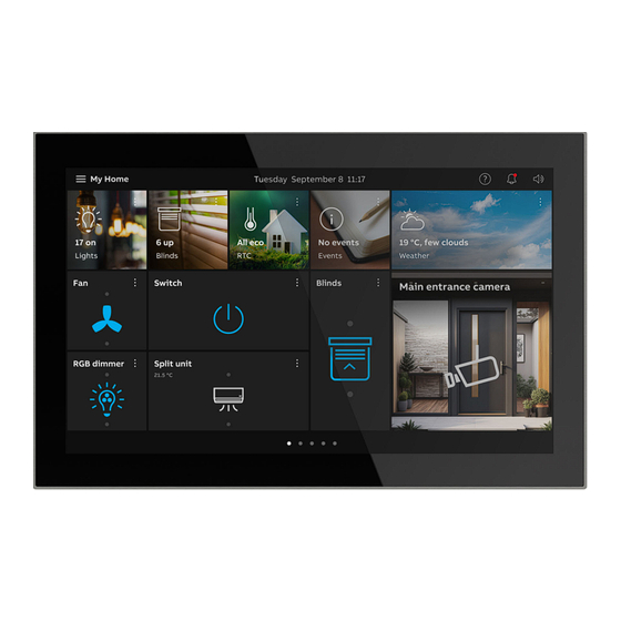
Page 52: Operation
Operation Operation 10.1 General control and display functions After the device has been connected to the power supply, the boot-up process starts. Then the parameterized main operating page (homepage) is displayed. This is marked with a house in the page display. Fig. - Page 53 Operation Pos. Description [10] Display of available operating pages [11] Callup of the main operating page Editing function [12] The control elements on the dashboard can be freely adjusted via the editing function see ■ chapter 10.2 “Control elements“ on page 54. [13] Access to general settings The individual operating pages can be called up by swiping the user...
-
Page 54: Control Elements
Operation 10.2 Control elements Control elements are used to fulfil the basic functions such as "Switching", "Dimming", Blinds", "Scenes" and RTC. The elements can also contain switches, buttons and sliders. Available are: Button operation Execution of function with a single press Tapping operation Execution of function by pressing and holding Control operation... -
Page 55: Basic Structures Of Control Elements
Operation 10.2.1 Basic structures of control elements Fig. 39: Various statuses of the same control element Pos. Description Name of device Device inactive If the device is inactive, the button is displayed as follows: Type of button "icon" ■ – During inactivity the button is displayed white. Device is active If the device is active, the button is displayed as follows: Type of button "icon"... -
Page 56: Additional Basic Principles
Operation 10.2.2 Additional basic principles Fig. 40: Basic principles Function buttons of blind control elements can, for example, display the different stages of blinds by means of alternating icons (e.g. alternating visualisation in the icon). Fig. 41: Additional basic principles Default settings of steps or levels (e.g. -
Page 57: Adjustable Control Elements
"Off"). Notice The push-button control elements can be used for the operation of Ledvance lamps. If a Ledvance lamp is available in your ABB-free@home ® system, this is transmitted automatically to the panel. Please note that these functions are only ®... - Page 58 Operation Blind (basic version can be further adjusted, e.g. with value display) Blind control elements can be used to implement the activation of blinds, awnings, doors and other motor-driven actuators. Control Status Function element The blind control element in its extended control settings has a button for stepwise switching (up/down) of blinds.
- Page 59 Operation Fan switch Fan switches (step switches) can be used to implement switching sequences. A step switch, so to speak, combines several push-buttons into one control element. Control element Status Function Fan switch control element The version has two buttons top and bottom for calling up the next or previous step and via a button in the middle.
- Page 60 Operation Audio control (basic version) All audio settings for connected audio devices can be easily controlled with the aid of this control element. Control element Status Function Corresponding to the default settings, a variety of audio functions can be called up directly via Audio control the buttons.
- Page 61 Operation Camera The camera control element can be used to open and control the camera surveillance. Control element Status Function The camera control element can be used to call Camera up and carry out camera functions fast. Home appliances With home appliance control elements, connected home appliances can be activated. Control element Status Function...
- Page 62 Operation Action Actions can be deactivated or activated with control elements for actions. Control element Status Function Actions can be activated and deactivated via control elements for actions. Action For this the actions must first be created and linked with the control element. Triggers Triggers for certain actions or scenes can be linked with trigger control elements.
-
Page 63: Special Functions
Operation 10.3 Special functions 10.3.1 Editing Different changes can be made to control elements via the "Edit" function. The "Edit" function can only be called up via the main operating page and the operating pages. Moving / deleting control elements: Fig. -
Page 64: Adding Control Elements To The Dashboard
Operation 4. Tap on the change picture button to upload a different graphic. 5. Select a picture from the available graphics. – The picture is uploaded. 6. If necessary, adjust the picture cutout. Notice This function is available for the "Scene" control element. 10.3.2 Adding control elements to the dashboard Especially constantly used control elements can be added to the dashboard. -
Page 65: Operating Actions Of The "Door Communication" Application
Operation 10.4 Operating actions of the "Door communication" application Via the door communication application different functions of the door communication can be used. This also includes: Video surveillance ■ Video call ■ Audio call ■ Door opener ■ The call-up of the "Door communication" application is described in the following. 1. -
Page 66: Setting Up Of Video Surveillance
Operation 10.4.1 Setting up of video surveillance All areas in which a surveillance camera is available can be viewed via the control elements for video surveillance. Notice The panel supports communication protocols UDP and TCP/IP. 1. The function is called up by tapping on the control element of the respective surveillance camera. -
Page 67: Establishing A Speech And Video Connection
Operation If there is a person in a camera area, an audio or video connection can be established. In addition, the door opener can be actuated or the light switched. 10.4.2 Establishing a speech and video connection As soon as a visitor presses the bell of a station, this is signalled on the panel as a bell call (Display of the telephone receiver icon in the monitor of the bell call). -
Page 68: Opening The Door
Operation Accepting calls (establishing speech and video connection) Calls can be accepted with or without video. The acceptance of calls is described in the following: 1. The function is called up via the handset button [4]. The following functions are available while establishing the speech and video connection: Set the volume by tapping the toothed wheel icon (move the controller to the right or left). -
Page 69: Activating Mute (Mite Timer)
Operation 10.4.4 Activating mute (mite timer) The call tone of the panel can be switched on and off. This setting has a time limit. 1. The function is called up via the bell button. Fig. 48: Muting For mute activation (mute timer) the following functions are available: No call is pending: "Mute"... -
Page 70: Switching Light
Operation 10.4.5 Switching light The lamp of the outdoor station can be switched via the lamp button. 1. The function is called up via the lamp button. 2. Press the lamp button for the following function ("Switch light" button actuated): –... -
Page 71: Control Actions Of Additional Applications
Operation 10.5 Control actions of additional applications 10.5.1 Notification Center The panel offers protection and information via the notification center. You can view the call history and information about malfunctions or faults. Message contacts, sensors and their functionality can be monitored. Notice Depending on the parameterization, only certain functions are available in the application... - Page 72 Operation Call history All the latest calls accepted and made are shown in the call history. Also snapshots available in the call history are displayed. Fig. 50: Call history Pos. Description Selected video call Call status (missed, incoming, outgoing, internal, external call) Deleting the entire call history 1.
- Page 73 Operation Messages Current and and archived messages can be displayed and edited in the notifications. There are different types of messages: Notice ■ Alarm ■ Error ■ Fig. 51: Fault and alarm messages Current notifications are marked with a red dot next to the warning icon. 1.
-
Page 74: Indoor Air Sensor
If an indoor air sensor has been added to the ABB-free@home system (e.g. Control element xgang), the display of air quality can be called up via the dashboard of the ABB OneTouch 7. The following values are determined by the AQI (Air Quality Index) sensors: in ppm (parts per million / millionth) with an additional graphic display / evaluation of the ■... -
Page 75: Radiator Thermostat
The temperature can be regulated via radiator thermostats to a previously set value set value. Also frost protection and valve protection functions can be activated. The ABB OneTouch 7 can be combined with a radiator thermostat as extension unit. If a ®... -
Page 76: System Settings
Operation 10.6 System settings Within the system settings general adjustments appropriate to the device can be made. These are described as follows. Fig. 53: System settings (example illustration) The system settings are called up as follows: 1. Tap on the hamburger menu at the top left on the main operating page (homepage). 2. - Page 77 House telephones can be managed in the intercom list and Intercom list enabled for the display on the dashboard (only available in connection with ABB-Welcome IP or ABB-Welcome ® Here the program button for the primary function is added Program button and set.
-
Page 78: System Settings - Display
Operation 10.6.1 System settings - Display In the system settings under "Display", general settings such as screen brightness and the layout can be specified. Also a screen saver can be specified. Fig. 54: Display - Settings Activate display cleaning mode To ensure that no function is triggered unintentionally during cleaning of the device, it can be disabled for a certain time. - Page 79 Operation If necessary, the appearance of the control elements can then also be specified. Here one can switch between a reduced and a detailed layout. Setting the screen saver A screen saver can be activated if the display is not used. Here you can select between a clock, slideshow and weather.
-
Page 80: System Settings - Sound
Operation 10.6.2 System Settings - Sound In the system settings under "Sound", general settings and adjustments for click and alarm tones can be specified. General After activating the checkbox "Activate click sound", the percentage for click sounds can be specified with the slider. Also the volume of the sounding alarm tones for connection faults can be specified via a slider. - Page 81 Operation Door communication The volume of the bell sound of the door communication is set via the slider. After activating the "Repeat bell sound" checkbox, the bell sound is repeated during a call. A bell sound can be specified for each station. Fig.
-
Page 82: System Settings - Network Connections
Operation 10.6.3 System settings - Network connections System settings can be used to make adjustments to the network connections. In addition, a connection to the app and to the MyBuildings portal can be established. The network connection can be established either via LAN or WiFi. Establish LAN connection 1. - Page 83 Operation Establishing a WiFi connection A WiFi connection can be established automatically or manually after activating the WiFi function. 1. Specify network type on "WiFi". 2. Establishing a network connection via "Connect manually" or automatically. 3. Scan for available networks. 4.
- Page 84 Operation Download the app ® The app ABB-free@home Next App can be downloaded by scanning the QR code in the App tab. Fig. 60: Network connections - App Then a connection with the web-interface of free@home can be established via the app tab by scanning the QR code.
- Page 85 Operation Establishing a connection to the MyBuildings portal For the remote access a connection must be established to the myBuildings portal. 1. Tap on "Log in" in tab MyBuildings. 2. Enter the login data. 3. Confirm with a tap on "Login". –...
-
Page 86: System Settings - Time And Date
Operation 10.6.4 System settings - Time and date All relevant data can be specified in the time and data settings. Also an automatic time change can be defined. Fig. 61: Time and date settings Product manual 2CKA000073B0036 │86... -
Page 87: System Settings - Access Management
Operation 10.6.5 System settings - Access management The settings of the access management make possible the specification of PIN codes for secured areas, outdoor stations and access modules. All available control mechanisms and devices are listed here and can be equipped with a PIN code. Fig. -
Page 88: System Settings - User Settings
Operation 10.6.6 System settings - User settings The panel language and the function of sensors and door communication can be set within the user settings. Also the user settings can be reset. Language and region The language of the panel and the separators to be used can be specified via the "Language" tab. - Page 89 Operation Door communication The "Door communication" tab can be used to specify how the system is to respond during the recording of snapshots and missed door calls. Fig. 64: User settings - Door communication Automatic screenshots ■ Options: Deactivate Activate When the checkbox is activated, the snapshots are taken automatically.
- Page 90 Operation Reset option The "Reset option" tab can be used to reset the settings assigned to a user. For this the "Reset settings" button must be tapped. Then the reset of the settings must be confirmed with "Yes". Fig. 65: User settings –...
-
Page 91: System Settings - Video Surveillance
New IP and Welcome cameras can be added and existing cameras can be managed in the video surveillance area. Notice The ABB OneTouch 7 only supports IP cameras of type ONVIF/RTSP. ONVIF is always set automatically. Adding IP camera IP cameras can be added and edited via the IP camera tab. The system can be searched automatically for existing cameras. - Page 92 Operation IP cameras Fig. 67: Managing Deleting IP camera Integrated IP cameras can be deleted via the IP camera tab. The system can be searched automatically for existing cameras. 1. Select a camera in the camera list. 2. Visualise the camera menu by swiping to the left on the menu entry of the affected camera. 3.
-
Page 93: System Settings Intercom List
Operation 10.6.8 System settings Intercom list In the intercom list area new intercom functions for internal house calls can be added. Adding an intercom Adding an intercom Fig. 68: 1. Tap on the plus icon. 2. Add the desired intercom. 3. - Page 94 Operation Deleting an intercom Intercoms that are already integrated can be deleted from the intercom list by swiping to the left on the menu entry. Deleting an intercom Fig. 69: 1. Select an intercom in the intercom list. 2. Visualise the intercom menu by swiping to the left on the menu entry of the affected intercom.
-
Page 95: System Settings - Program Button
Operation 10.6.9 System settings - Program button New programming buttons can be added via the "Programming button" menu and the door communication can be managed. Adding programming button Programming button functions can be added and managed via the programming button tab. Fig. -
Page 96: 10.6.10 System Settings - Extended Settings
Operation 10.6.10 System settings - Extended settings Detail settings on the door communication and building automation can be made via the extended settings. If required, the system can be reset to the factory settings. The settings can only be made when the PIN code was entered successfully beforehand. Door communication Fig. -
Page 97: Building Automation
Operation Building automation The operating mode of the panel can be specified in the building automation tab. It can function as internal SysAP or linked with an external SysAP of an existing free@home installation. Fig. 72: System settings - extended settings - building automation (internal SysAP) When using in combination with an existing external SysAp, a connection must be established by tapping on the corresponding button. - Page 98 Operation Resetting system to factory settings The system can be reset to the factory settings in the "Reset option" tab. 1. Tap on the "Reset to factory settings" button. 2. Confirm the enquiry. – The system will be reset to the factory settings. Notice After a successful reset, the system is restarted.
-
Page 99: 10.6.11 System Settings - Software Update
Operation 10.6.11 System settings - Software update Software updates can be searched for via the Internet, downloaded and installed. Update via the internet Fig. 74: System settings - Software update 1. Tap on the "Search for updates" button. – The system then searches for available updates. A new available update is displayed in the dialogue. -
Page 100: 10.6.12 System Settings - Via
Operation 10.6.12 System settings - Via Via this page, information about the network, Welcome and free@home devices, general matters (license agreements) and QR codes can be called up. You can switch between the different system information via the tabs at the upper edge of the screen. Fig. -
Page 101: Terminal Resistor
Operation Terminal resistor 10.6.13 Station a1 b DC+ GND Station (PoE) X 100 X 00 P / S R C X100 X 00 P/S R C Fig. 76: Terminal resistor In video installations or mixed audio and video installations, set the terminal resistor for the last devices of a branch on "ON". -
Page 102: Update
Update Update A software update can be performed by means of the system settings on the panel. Various update options are available (see chapter 10.6.11 “System settings - Software update“ on page 99). Product manual 2CKA000073B0036 │102... -
Page 103: Addressing
This programming process is designated as "Addressing". ® The process of addressing is generally the same for all devices of the ABB-Welcome system. The addressing is performed via three trimmers and two Dip switches. -
Page 104: Maintenance
Maintenance Maintenance 13.1 Cleaning Caution! - Risk of damaging the device! When spraying on cleaning agents, these can enter the device through ■ crevices. – Do not spray cleaning agents directly onto the device. Aggressive cleaning agents can damage the surface of the device. ■... -
Page 105: Notes
Notes Notes Product manual 2CKA000073B0036 │105... -
Page 106: Index
Circuit diagrams ........21, 30 Notes on the instruction manual ......5 Cleaning ............ 104 Notification Center ........71 Commissioning via ABB-free@home® ....36, 37 Connection, installation / mounting ....22 Opening the door ........... 68 Connection, installation and addressing ... 14, 29 Operating actions of the application .... - Page 107 Index System Access Point ........37 Via .................100 System settings ..........76 Video surveillance ............91 Access management ............87 Display ................78 Target group ..........8 Extended settings ............96 Technical data ..........18 Intercom list ..............93 Terminal resistor ......... 101 Network connections ............
- Page 108 Busch-Jaeger Elektro GmbH A member of the ABB Group Freisenbergstraße 2 D-58513 Lüdenscheid, Germany https://new.abb.com/en Customer service: Tel.: +49 2351 956-1600 Copyright © 2024 Busch-Jaeger Elektro GmbH All rights reserved...
Need help?
Do you have a question about the ABB-free@home OneTouch 7 M2249-2 Series and is the answer not in the manual?
Questions and answers