Advertisement
Quick Links
Hybrid Receiver
Hybrid Receiver
GEN-RECEIVER
GEN-RECEIVER
1
BEFORE INSTALLATION
Warning
Failure to follow the
instructions provided
and improper handling
may cause death or
serious injury.
Caution
Failure to follow the
instructions provided
and improper handling
may cause injury and/or
property damage.
This symbol indicates prohibition. The specific prohibited action is provided in and/or around the figure.
This symbol requires an action or gives an instruction.
The GEN-RECEIVER Hybrid Receiver is designed to receive signals from learned-in wireless sensors, and activate the corresponding Alarm/Trouble
outputs based on function switch settings.
With four channels available, each channel includes both alarm and trouble outputs and can learn up to 10 wireless devices. This allows a maximum total
of 40 wireless devices for the GEN-RECEIVER.
Whenever any of the learned-in devices of a specific channel is triggered or experiences fault, the corresponding channel's Alarm/Trouble output will be
activated.
If using the repeater to retransmit signals from devices to GEN-RECEIVER, both the repeater and the devices need to be learned into GEN-RECEIVER,
but they don't need to be in the same channel. A repeater that is learned into any of the 4 channels of GEN-RECEIVER can process signals of all 4
channels' devices as long as the devices are paired with the repeater.
2
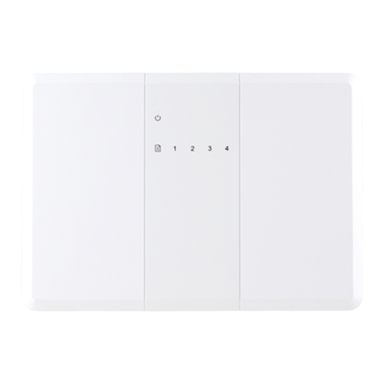
IDENTIFYING THE PARTS
1. Power LED (Green)
● On: On AC power.
● Flashes once every second: AC Power failure.
● Flashes once every two seconds : Low Battery.
● Quick Flash: Battery Missing/Battery Switch OFF.
2. Channel 1~4 LED (Red)
● The corresponding Channel LED will light up when any of the learned-in devices of the channel experiences fault.
- Device Low Battery: One flash per second.
- Device Tamper Open: Two flashes per second.
- Device Supervision failure: Three flashes per second.
- Device AC Fail: Four flashes per second. (For Repeater Only)
● The corresponding Channel LED will also light up when the channel is in learning mode.
- Learning Mode: Quick Flash.
● All Channel LEDs will light up in Test Mode.
- Test Mode: All channel LEDs flash once every 2 seconds.
3. Mounting Holes
4. Wiring Hole
Do not touch the unit base or power terminals of the product with a wet hand. (Also, if the product is wet
after rain, do not touch it.) It may cause electric shock.
Never attempt to disassemble or repair the product. It may cause fire or damage to the devices.
[Handling of Batteries]
Fire, explosion and severe burn hazard. Do not recharge, short circuit, crush, disassemble, heat above 100°C,
incinerate, or expose contents to water. Do not solder directly to the cell.
Do not pour water over the product. The water may enter and may cause damage to the devices.
Clean and check the product periodically for safe use. If any problem is found, do not attempt to use the product
as it is and inform your installer.
If you do not use the product for a long period of time, remove the battery. Keep it in a cool, dark area.
Dispose batteries according to local regulations.
Front View
INSTALLATION INSTRUCTIONS
Back View
-1-
No.59-3508-0 2406-13
PIR
Advertisement

Subscribe to Our Youtube Channel
Related Manuals for Optex GEN-RECEIVER


Summary of Contents for Optex GEN-RECEIVER
- Page 1 If using the repeater to retransmit signals from devices to GEN-RECEIVER, both the repeater and the devices need to be learned into GEN-RECEIVER, but they don’t need to be in the same channel. A repeater that is learned into any of the 4 channels of GEN-RECEIVER can process signals of all 4 channels’...
- Page 2 ● 12 VDC 1 A switching power connection. 8. Reset Input (for All Channels) ● When the Reset Input closes, GEN-RECEIVER will restore the Alarm outputs & Trouble outputs of all channels. All device errors are reset. ● If the Reset Input’s closed condition persists, GEN-RECEIVER will bypass all alarm and trouble signals from learned-in devices of all channels.
-
Page 3: Power Supply
FUNCTION SWITCH BLOCK Dip Switch Set 0 (for All Channels) Dip Switch Set 0 is used to enable/disable low battery and supervision failure as trouble output, and to put the GEN-RECEIVER into Test Mode for all channels. Dip Switch Set 0... - Page 4 GEN-RECEIVER, but they don’t need to be in the same channel. A repeater that is learned into any of the 4 channels of GEN-RECEIVER can process signals of all 4 channels’ devices as long as the devices are paired with the repeater.
-
Page 5: Normal Operation
Supervision Failure AC Fail. ● When GEN-RECEIVER receives test code from PIR/DC, it will emit a beep and the corresponding channel LED will flash once. CLEAR DEVICES (For Each Channel) This function is used to clear all sensor learned-in memory for each channel. - Page 6 10 SPECIFICATIONS Model GEN-RECEIVER 433 MHz Frequency Power Source 12 VDC/1 A Power LED indicator 1 Green LED Channel LED indicator 4 Red LEDs for 4 channels (one for each) Battery backup Ni-Mh 7.2 V 600 mAh Alarm Output CH1-4 Relay dry contact out (Capacity 0.5 A 125 VAC or 1 A 30 VDC)
Need help?
Do you have a question about the GEN-RECEIVER and is the answer not in the manual?
Questions and answers