Advertisement
SUPPleMenTal InSTRUCTIonS
US
Tested For 100 LBS.
ASME
Working Pressure
VENTING GUIDELINES
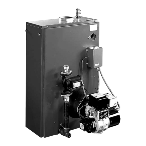
PFO and DPFO Model
CaST IRon, PReSSURe-FIRed,
WeT BaSe HoT WaTeR BoIleRS
!
CAUTION
Do not use this vent pipe or fit-
tings for venting incinerators of any kind.
!
WARNING
venting system, read all of these instructions and refer to
the vent pipe manufacturer's instructions.
Failure to use a proper venting system will void the manu-
facturer's warranty and may result in rapid deterioration of
the venting system, a potential health hazard.
Faulty vent installation can allow toxic fumes to be released
into living areas. This may cause serious bodily injury or
property damage. Vent performance may also be affected by
improper assembly.
Install separate vents for forced exhaust appliances and
natural draft appliances. A common vent between natural
draft and forced exhaust appliances may cause toxic gases
to exhaust through the natural draft appliance rather than
to the outside air. Breathing exhaust gases will cause serious
personal injury or death.
!
WARNING
venting should be done ONLY by a qualified expert and
in accordance with the appropriate manual. Installing or
venting a boiler or any other gas appliance with improper
methods or materials may result in serious injury or death
due to fire or asphyxiation from poisonous gases such as
carbon monoxide which is odorless and invisible.
For correct installation of your
All installations of boilers and
P/N 240005665, Rev. A [10/08]
Advertisement
Table of Contents

Subscribe to Our Youtube Channel
Related Manuals for ECR PFO


Summary of Contents for ECR PFO
- Page 1 SUPPleMenTal InSTRUCTIonS VENTING GUIDELINES PFO and DPFO Model CaST IRon, PReSSURe-FIRed, WeT BaSe HoT WaTeR BoIleRS CAUTION Do not use this vent pipe or fit- tings for venting incinerators of any kind. WARNING For correct installation of your venting system, read all of these instructions and refer to the vent pipe manufacturer’s instructions.
-
Page 2: Installations
FRESH AIR FOR COMBUSTION - CHIMNEY VENTED BOILERS Boiler in Confined Space WARNING Be sure to provide enough fresh air for combustion. Enough air ensures proper combustion and assures that no hazard will develop due to the lack of All Air From Inside Building: The confined space shall be provided with two permanent openings communicating di- oxygen. -
Page 3: Applicable Federal Codes
FRESH AIR FOR COMBUSTION - CHIMNEY VENTED BOILERS All Air From Outdoors: The confined space shall be provided Fresh Air Duct Capacities with two permanent openings, one commencing within 12 The following table shows fresh air duct capacities (in Btuh) inches of the top and one commencing within 12 inches of the for ducts supplying fresh air to boilers in tightly constructed bottom of the enclosure. - Page 4 FRESH AIR FOR COMBUSTION - CHIMNEY VENTED BOILERS Place in operation the appliance being inspected. Follow NOTICE For oil-fired boilers for connec- the lighting instructions. Adjust thermostat so appliance tions to vents or chimneys, vent installations shall be in will operate continuously. accordance with applicable provisions of “Installation of Oil, Burning Equipment”...
- Page 5 INDOOR CHIMNEY VENTED BOILERS Chimney Lining WARNING All installations of boilers and venting should be done only by a qualified expert and in accordance with the appropriate manual. Installing or Use a suitably sized Type B1 vent liner or suitable corrugated venting a boiler or any other gas appliance with improper liner.
- Page 6 INDOOR CHIMNEY VENTED BOILERS The chimney should extend at least two feet above any A draft regulator is recommended with or without a object within 10 feet and extend at least three feet higher neutral pressure point adjustor in all cases where there is than roof at point of exit.
- Page 7 INDOOR DIRECT VENT BOILERS -- FOR OIL-FIRED BOILERS ONLY!! The optional Field Direct Vent System (FDVS) is to be used in The exhaust terminal included in the FDVS kit is a model conjunction with the boiler for indoor installations requiring FDVS stainless steel vent hood.
- Page 8 INDOOR DIRECT VENT BOILERS -- FOR OIL-FIRED BOILERS ONLY!! Location of the termination of Figure 5 - Exterior Exhaust Terminal Locations the vent pipe shall be in accor- dance with the National Fuel Gas Code; ANSI, Z223.1 (see requirements below) and any local codes which are appli- cable.
-
Page 9: Installation
INDOOR DIRECT VENT BOILERS -- FOR OIL-FIRED BOILERS ONLY!! Installation Exhaust Flue Pipe Use inside wall end plate as a template to mark hole loca- The exhaust flue pipe from the boiler must be 6’ or less in tion. Cut hole 1 inch larger than marked hole to facilitate length in order to minimize condensation. - Page 10 INDOOR DIRECT VENT BOILERS -- FOR OIL-FIRED BOILERS ONLY!! Alternate Ground Vent When the structure of the house or the exterior grade does not allow location of the vent terminal in compliance with the instruc- Figure 6. tions in this manual, an alternative is to vent into a clay pipe system installed underground. Refer to notes in Figure 6 - Typical Underground Vent Installation Seal opening in foundation around clay pipe with hydrau- NOTES:...
- Page 11 TYPICAL VENT SAFETY PRESSURE SWITCH INSTALLATION This boiler may also be installed with a pressure switch. For side-wall vented boilers the unit uses a .35” w.c. pressure switch. It is mounted to the jacket using the screws provided and is wired to the T-T terminals on the Oil Primary for oil-fired boilers.
Need help?
Do you have a question about the PFO and is the answer not in the manual?
Questions and answers