Table of Contents

Related Manuals for ECR CHB-100


Summary of Contents for ECR CHB-100
- Page 1 Model CHB-100 CHB-130 WALL MOUNTED GAS BOILER INSTALLATION, OPERATION & MAINTENANCE MANUAL Manufactured for: ECR International, Inc. 2201 Dwyer Avenue, Utica NY 13501 web site: www.ecrinternational.com P/N# 240010633, Rev. B [07/17/2014]...
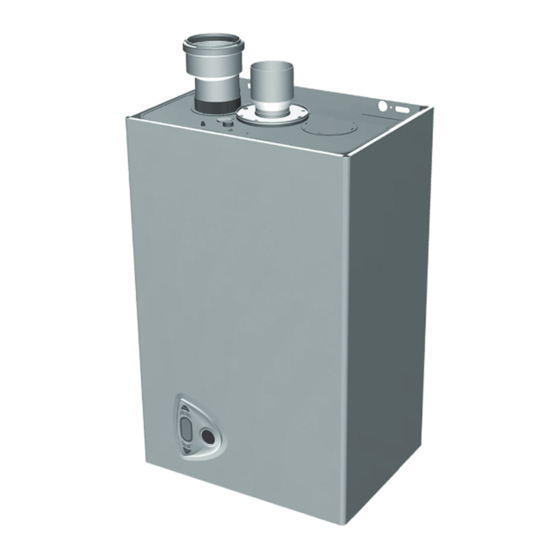
- Page 2 DIMENSIONS Figure 1 - Overall Dimensions = Gas Inlet - 3/4” FPT 10 = System Delivery - 1” MPT 11 = System Return - 1” MPT *209 = Hot Water Tank Delivery - 3/4” Capped *210 = Hot Water Tank Return - 3/4” Capped * BSPT To NPT Adapters Included...
-
Page 3: Table Of Contents
10 - Operating Instructions ....................26 11 - General Maintenance And Cleaning ................32 12 - Ratings And Capacities ....................33 13 - Trouble Shooting......................36 Wiring diagram ....................... 37 Repair Parts List - CHB-100 ..................... 38 Repair Parts List - CHB-130 ..................... 44... -
Page 4: Introduction
• Integral Dual Limit. Information and specifi cations outlined in this manual in effect at the time of printing of this manual. ECR International, Inc. reserves the right to discontinue, change specifi cations or system design at any time without... -
Page 5: Important Safety Information
2 - IMPORTANT SAFETY INFORMATION 2.1 General 2.3 Installation shall conform to requirements of Boiler installation shall be completed by qualifi ed agency. authority having jurisdiction or in absence of such See glossary for additional information. requirements: • United States •... -
Page 6: General View And Main Components
3 - GENERAL VIEW AND MAIN COMPONENTS Figure 2 Component Listing... - Page 7 3 - GENERAL VIEW AND MAIN COMPONENTS Item Description Number Sealed Chamber Gas Inlet Supply System System Return Modulating Fan Combustion Chamber Burner Copper Heat Exchanger Exhaust Manifold Exhaust Outlet Manifold Heating circulating pump Automatic Air Vent Gas Valve Ignition and Detection Electrode 3 Way Diverter Valve Water Pressure Switch Hot Water Tank Delivery...
- Page 8 3 - GENERAL VIEW AND MAIN COMPONENTS WARNING Fire, explosion, asphyxiation and electrical shock hazard. Disconnect electrical power supply and turn off gas at shutoff valve before attemting to remove boiler jacket. Failure to follow these instructions could result in death or serious injury.
-
Page 9: Locating Boiler
4 - LOCATING BOILER 4.1 Boiler Location Considerations Figure 5 - Boiler Clearances • Ambient room temperature always above 32°F (0°C) to prevent freezing. • Approved for installation in closets. • Protect gas ignition system components from water (dripping, spraying, rain, etc.) during operation and service (circulator replacement, control replacement, etc.). - Page 10 4 - LOCATING BOILER Pre-pipe supply and return water connections Figure 6 - Wall Mounting Bracket with factory fi ttings before wall mounting. 4.3 Wall Mounting 2⅜” 2⅜” Mount boiler on wall using wall mounting bracket included (2.4cm) (2.4cm) with unit. •...
-
Page 11: Hydronic Piping
5 - HYDRONIC PIPING 5.1 General Conditioning chemicals must ensure complete deoxygenation of water and contain specifi c protective agents for yellow • Install piping in accordance with authority having jurisdiction. metals (copper and its alloys), anti-fouling agents for NOTICE limescale at least up to 150 ppm CaCO3, pH neutral stabilizers and, in low temperature systems, specifi... - Page 12 5 - HYDRONIC PIPING • System piping connected to heating coils located in air Figure 7 - Indirect Tank Performance Chart handling unit exposed to refrigerated air circulation. Install fl ow control valves or other automatic means to prevent gravity circulation of boiler water during cooling cycle. 5.4 Storage Tank Connection For Domestic Hot Water Production •...
- Page 13 5 - HYDRONIC PIPING • Size and arrange discharge piping to avoid reducing Figure 9 - Safety Relief Valve Discharge safety relief valve relieving capacity below minimum Piping relief valve capacity stated on rating plate. • Run pipe as short and straight as possible to location protecting user from scalding and properly drain piping.
- Page 14 5 - HYDRONIC PIPING Figure 10 - Hydronic Piping Domestic Hot Water Outlet Domestic Cold Water Inlet Heating System Supply Heating System Return Diverter Valve 209 Hot Water Tank Delivery 210 Hot Water Tank Return...
-
Page 15: Combustion Air And Vent Piping - Category I (Chimney Vent)
6 - COMBUSTION AIR AND VENT PIPING - CATEGORY I (CHIMNEY VENT) Common venting shall not be allowed. Boiler and WARNING other certifi ed appliances. appliances can share same Boiler and venting installations shall be performed chimney vent. Consult appropriate Vent Sizing Tables by a qualifi... -
Page 16: Removing Existing Boiler From Common Venting System
6 - COMBUSTION AIR AND VENT PIPING- CATEGORY I (CHIMNEY VENT) 6.2 Minimum Vent Pipe Clearance Test for spillage at the draft hood relief opening after 5 minutes of main burner operation. Use fl ame of a • Use Type B vent pipe through crawl space. Where vent match or candle, or smoke from a cigarette, cigar, or pipe passes through combustible wall or partition, use pipe. -
Page 17: Combustion Air And Vent Piping Of Direct Vent And Category Iii
4 feet (1.22m) horizontal A. When venting through combustible walls, distance is maintained, from electric meters, gas combustible clearances must be considered. ECR meters, regulators and relief equipment. vent termination, 5612601, is a certifi ed direct vent... - Page 18 6 - COMBUSTION AIR AND VENT PIPING OF DIRECT VENT AND CATEGORY III If the horizontal vent must go through a crawl space or WARNING other unheated space, the cool temperatures will likely Vent extending through exterior wall shall not cause the fl...
- Page 19 6 - COMBUSTION AIR AND VENTILATION Provide combustion air and ventilation air in accordance • All Outdoor Air. Provide permanent opening(s) with the section “Air for Combustion and Ventilation,” communicating directly or by ducts with outdoors. of the National Fuel Gas Code, ANSI Z223.1/NFPA 54, ◊...
- Page 20 6 - COMBUSTION AIR AND VENT PIPING Figure 12 - Horizontal Venting Clearances NOTICE Figure 13 - Two Pipe Venting Maintain 12” (30cm) US, 18” (46cm) Canada clearance above highest anticipated snow level or grade. = Combustion Air / = Venting)
- Page 21 6 - COMBUSTION AIR AND VENT PIPING NOTICE Figure 14 - Chimney Venting with Room Air Single Wall Refer to section 6.1, numbers 3 through 12, page 15 of this manual for proper installation. = Combustion Air / = Venting) Figure 15 - Chimney Venting with Outside Air Single Wall = Combustion Air /...
-
Page 22: Gas Supply Piping
7 - GAS SUPPLY PIPING Figure 16 Manual Main Gas Shutoff Valve CAUTION Outside Boiler Jacket WHAT TO DO IF YOU SMELL GAS With Manufacturer Suggested Piping With Drip Leg • Do not try to light any appliance. • Do not touch any electrical switch; do not use any phone in your building. -
Page 23: Electrical Connections
8 - ELECTRICAL CONNECTIONS Figure 17 - Terminal Block WARNING Electrical shock hazard. Turn OFF electrical power supply at service panel before making electrical connections. Failure to do so could result in death or serious injury. 8.1 General Electrically bond boiler to ground in accordance with requirements of authority having jurisdiction. -
Page 24: Start Up Procedure
9 - START UP PROCEDURE 9.1 Fill Boiler With Water And Purge Air WARNING NOTICE Asphyxiation hazard. Carbon monoxide is odorless, To maintain boiler effi ciency and prevent boiling tasteless, clear colorless gas, which is highly toxic. inside the heat exchanger, fl ush entire heating Carbon monoxide production shall not exceed system until clean. - Page 25 9 - START UP PROCEDURE 9.6 Check Combustion Figure 18 - Test Ports Natural Gas Vent Gases Test Measure input. English unitsTurn off gas to all other Port appliances. • Activate some heating zones to dissipate heat. • Set boiler on high fi re. •...
-
Page 26: Operating Instructions
10 - OPERATING INSTRUCTIONS WARNING CAUTION If you do not follow these instructions WHAT TO DO IF YOU SMELL GAS exactly, a fi re or explosion may result • Do not try to light any appliance. causing property damage, personal injury •... -
Page 27: Control Panel
10 - OPERATING INSTRUCTIONS 10.3 Checks During Operation 10.5 Indicator During Operation • Boiler is arranged for connection to an external storage Heating tank for hot water production (optional). All functions relevant to domestic hot water production are only Call for heat (generated by Room Thermostat) is indicated active with the optional water tank connected. - Page 28 10 - OPERATING INSTRUCTIONS Boiler Ignition Summer/Winter Switch over Supply unit with electricity. NOTICE Activating this button will keep your boiler from operating. Verify that boiler is not required to run Domestic Hot Water (DHW) needs. Press the button for 2 seconds. Boiler ignition For 120 seconds display will show FH which identifi...
- Page 29 10 - OPERATING INSTRUCTIONS Hot water tank exclusion (economy) Compensation curve and curve offset Hot water tank temperature maintaining/heating can be Press the button (see item 6 on the control panel display) excluded by the user. If excluded, domestic hot water will for 5 seconds once to display the actual compensation not be delivered.
- Page 30 10 - OPERATING INSTRUCTIONS Press the button (see item 6 on the control panel display) for 5 seconds again to exit parallel curve adjustment mode. If the room temperature is lower lower than the required value, it is advisable to set a higher order curve and vice versa.
- Page 31 10 - OPERATING INSTRUCTIONS Water system pressure adjustment The fi lling pressure with system cold, read on the boiler water gauge, must be approximately 11 psi. If the system pressure falls to values below minimum, the boiler control will activate fault F37. Low system pressure fault Once the system pressure is restored, the boiler will activate the 120-second air venting cycle indicated on the...
-
Page 32: General Maintenance And Cleaning
11 - GENERAL MAINTENANCE AND CLEANING 11.1 Beginning of Each Heating Season 11.2 Annual Shut Down Procedure • Check boiler area is free from combustible materials, • Follow instructions “To Turn Off Gas To Appliance” unless gasoline, and other fl ammable vapors and liquids. boiler is also used to supply domestic hot water. -
Page 33: Ratings And Capacities
12 - RATINGS AND CAPACITIES... - Page 34 Size Capacity AFUE (MBH) (1)(3) Maximum Minimum (MBH) (1)(2) CHB-100 31.5 73.0 CHB-130 43.5 96.0 1000 Btu/hr (British Thermal Units Per Hour) Heating Capacity and AFUE (Annual Fuel Utilization Effi ciency) are based on DOE (Department of Energy) test procedures.
- Page 35 12 - RATINGS AND CAPACITIES Diagrams Manifold Gas Pressure W.C. Losses of load / head of circulators 20,00 18,00 16,00 14,00 12,00 10,00 8,00 6,00 4,00 2,00 0,00 10,0 Water Flow [GPM] A Boiler losses of head 1 - 2 - 3 Circulator speed...
-
Page 36: Trouble Shooting
13 - TROUBLE SHOOTING Diagnostics The boiler is equipped with an advanced self-diagnosis system. In case of a boiler fault, the display will fl ash indicating the fault code. There are faults that cause permanent shutdown (marked with the letter “A”): to restore operation just press the RESET button for 1 second or RESET;... -
Page 37: Wiring Diagram
WIRING DIAGRAM kOhm 138 - Optional Outdoor Sensor 155 - Optional Indirect Tank Sensor kOhm 370 - Field Source LWCO 120V 60Hz DBM34 +15V Important: Before connecting the room thermostat, remove the jumper on terminal block. Modulating fan 155 Hot water tank temperature probe (fi eld sourced) Heating circulating pump 278 Double sensor (Safety + Heating) DHW temperature sensor (see kit) -
Page 38: Repair Parts List - Chb-100
REPAIR PARTS LIST - CHB-100 Part Number Description FE3980B830 CASING "CTR"... - Page 39 REPAIR PARTS LIST - CHB-100 Part Number Description FE3980C200 KIT CONTROL BOX FE3980B850 KIT CONTROL BOARD DBM34 FE3980C210 KIT FRONT COVER "CTR" FE3980B840 KIT PRESS.TEMP.GAUGE FE3980C860 KIT WIRING FE3980C220 KIT MONO CABLE EL.
- Page 40 REPAIR PARTS LIST - CHB-100...
- Page 41 REPAIR PARTS LIST - CHB-100 Part Number Description FE3980B870 KIT GASKETS SET FE3980C230 MONO HEAT EXCHANGER FE3980C010 KIT GASKET FE3980C020 KIT CLIP D18 FE3980C040 TEMP SENSOR DP FE3980C050 KIT 3-WAY VALVE FE3980C060 KIT MOTOR 3-WAY VALVE TP FE3980B890 KIT PUMP FX3-FP...
- Page 42 REPAIR PARTS LIST - CHB-100...
- Page 43 REPAIR PARTS LIST - CHB-100 Part Number Description FE3980B930 KIT GASKETS SET FE3980C160 KIT FLUE GASES OUTLET BEND FE3980C100 FAN GASKET FE3980C250 KIT FAN FE3980C090 PRESSURE TEST POINT “VENTURI” FE3980C260 KIT BURNER 11 R.m. FE3980C280 KIT 11 INJECTOR 1.35mm NG FE3980C300 KIT 11 INJECTOR 0.85mm LP...
-
Page 44: Repair Parts List - Chb-130
REPAIR PARTS LIST - CHB-130 Part Number Description FE3980B830 CASING "CTR"... - Page 45 REPAIR PARTS LIST - CHB-130 Part Number Description FE3980C200 KIT CONTROL BOX FE3980B850 KIT CONTROL BOARD DBM34 FE3980C210 KIT FRONT COVER "CTR" FE3980B840 KIT PRESS.TEMP.GAUGE FE3980B860 KIT WIRING FE3980C220 KIT MONO CABLE EL.
- Page 46 REPAIR PARTS LIST - CHB-130...
- Page 47 REPAIR PARTS LIST - CHB-130 Part Number Description FE3980B870 KIT GASKETS SET FE3980B880 KIT MONO HEAT EXCHANGER FE3980C010 KIT 20 GASKET FE3980C020 KIT 10 CLIP D18 FE3980C040 TEMP SENSOR DP FE3980C050 KIT 3-WAY VALVE FE3980C060 MOTOR 3-WAY VALVE TP FE3980B890 PUMP FX3-FP FE3980B900 KIT AIR SEPARATOR...
- Page 48 REPAIR PARTS LIST - CHB-130...
- Page 49 REPAIR PARTS LIST - CHB-130 Part Number Description FE3980B930 KIT GASKETS SET FE3980C160 KIT FLUE GASES OUTLET BEND FE3980C100 KIT FAN GASKET FE3980B940 KIT FAN FE3980C090 KIT PRESSURE TEST POINT “VENTURI” FE3980C270 KIT BURNER 15 R.m. FE3980C290 KIT 15 INJECTOR 1.35mm NG FE3980B950 KIT 15 INJECTOR 0.85mm LP FE3980C120...
- Page 50 NOTES...
- Page 51 NOTES...
- Page 52 ECR International, Inc 2201 Dwyer Avenue, Utica NY 13501 web site: www.ecrinternational.com...
Need help?
Do you have a question about the CHB-100 and is the answer not in the manual?
Questions and answers